Table of Contents
- Audio Synth #1 - The project
- Audio Synth #2 - Board introduction and IDE setup
- Audio Synth #3 - Arduino to CmodS7 COMM Test
- Audio Synth #4 - Use PWM to control LED
- Audio Synth #5 - Testing the I2S PCM5102 DAC Decoder Board
- Audio Synth #6 - Sound generation with CmodS7
- Audio Synth #7 - Design challenge ends, project continues
===========================================================
Arduino design considerations
The original idea was to let Arduino handle all UI interaction (LCD screen display, parameter adjustments using knobs) and use Cmod S7 exclusively for sound generation and processing. The advantages of this approach is that firstly, it simplifies the FPGA development (an area in which I am a beginner) and secondly, it saves FPGA resources that can be used for sound generation rather than implementing control logic on a board with rather limited resources.
I am using an Arduino Uno for prototyping. It has a 6 channel, 10-bit ADC (pins A0-A5). Arduino Mini and Nano have 8ADC channels, while Mega has 16, so there are other alternatives if more channels will be needed. I plan to use I2C to control an LCD display, so I need to configure 2 out of the 6 ADC pins (A4, A5) as SDA, SCA I2C connections. This leaves only 4 ADC channels (A0-A3) that can be used for my project. These four analog inputs will be connected to potentiometers which will set various parameters’ values. (Please refer to the block diagram from Blog #1).
In terms of ADC programming there are two paths when using Arduino: the first is a function call aptly named analogRead (blocking, takes 100 microseconds to complete!), and the second is using an ISR (nonblocking, faster).
Some brief explanation now. The Arduino ADC requires 13 clock cycles to process an analog value. To get accurate results, the clock at the ADC needs to be slower than the system clock. Arduino uses a pre-scaling constant (128) to divide the system clock before applying it to the ADC. So, on the Arduino Uno running at 16MHz, the ADC clock is (16,000/128)KHz = 125KHz. It takes analogRead 13 ADC clock cycles (about 104 microseconds) to perform an AD conversion. Using an ISR is not only a lot faster (AD conversion can be done in one ADC clock cycle), but it is also non-blocking.
So, this is my programming approach on the Arduino side: a forever loop that reads ADC channels using an ISR. Whenever one of those values changes, the change is sent to Cmod S7, and the LCD screen is updated accordingly.
Here are a couple of relevant links:
- https://www.arduino.cc/reference/en/language/functions/analog-io/analogread/
- https://www.arduino.cc/en/Reference/UsingAVR
and here is the io.h header for the Atmel 328 on Arduino Uno https://github.com/vancegroup-mirrors/avr-libc/blob/master/avr-libc/include/avr/iom328p.h
Communication between Arduino and Cmod S7
Communication between Arduino and Cmod S7 can be done using either a proprietary or an existing protocol (e.g. I2C, SPI). There are a few reasons why I would like to write my simple data transfer protocol between Arduino and Cmod S7 (this is a simple pair name/value transfer, limited resources on the FPGA board, plus the learning aspects).
Arduino to CmodS7 COMM Project
To get started, I want to test some basics. The next project is very simple: CmodS 7 receives a digital signal (0 or 1) from Arduino, uses that signal to control the Blue LED, then returns the negated signal back to Arduino.
On the Arduino side, a slow clock signal of configurable duty cycle (milliseconds) is generated. To read and write digital signals I am using port manipulation because it is a lot faster than the digitalRead( ), digitalWrite( ) functions.
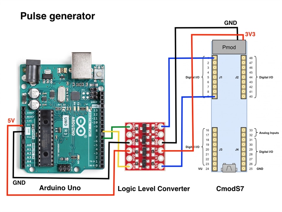
The figure below depicts the wiring diagram. Please note the presence of the logic level shifter between Arduino (5V) and Cmod S7 (3V3). The logic shifter uses N channel MOSFETs (BSS138). This type of shifter is used for I2C bus logic level shifting and will work at frequencies that don't exceed 400KHz (I2C Fast Mode).

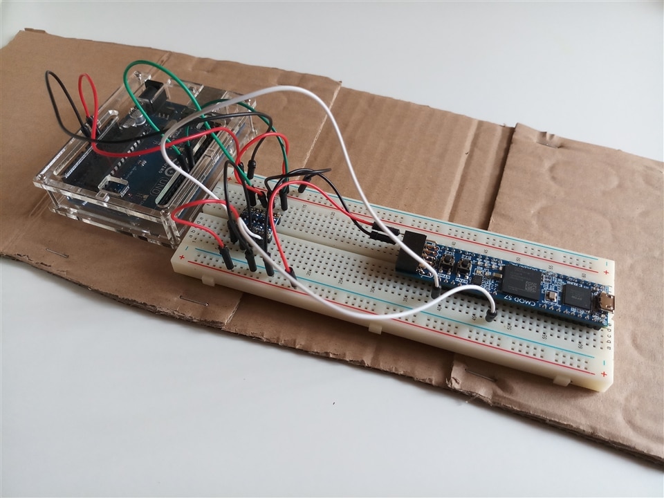
And this is a photo of my setup:

From what I read online, it seems that by using port manipulation on an Arduino running at 16MHz to toggle a digital output in a loop, one can generate a square wave up to 2.6MHz. Using the digitalRead( ) function allows one to generate a square wave around 106KHz. I would like to verify all these figures with my old Hantek USB scope which I haven't used in a while and it is currently in storage. Once I dig it out, I will update the blog with some screen captures.
To make sure I can use Arduino IDE, one future task is to implement and time the forever loop in Arduino (read ADC port, update LCD with new parameter values using I2C and send new values to Cmod S7). If things get sluggish, I will have to do native C development rather than use Arduino primitives and IDE.
ArduinoToCmodS7 Comm Project
On the Arduino Uno, bit 7 of port D is used to send the signal, and bit 0 of port B is used to read the incoming signal. The period of signal is hardcoded to 4000ms but one can change the value and recompile. Connect to Serial Console to check on the incoming signal.
On CmodS7, things are very simple: a source file and a constraint file (see lines 4, 11, 19)
Github Repository
Summer-of-FPGA/arduinoToCmodS7Comm at main · a3333333/Summer-of-FPGA (github.com)
