


Table of Contents
- Audio Synth #1 - The project
- Audio Synth #2 - Board introduction and IDE setup
- Audio Synth #3 - Arduino to CmodS7 COMM Test
- Audio Synth #4 - Use PWM to control LED
- Audio Synth #5 - Testing the I2S PCM5102 DAC Decoder Board
- Audio Synth #6 - Sound generation with CmodS7
- Audio Synth #7 - Design challenge ends, project continues
===========================================================
I2S protocol
I will be using a PCM5102 I2S DAC board for sound generation. “I2S is a serial bus standard used to communicate PCM audio data between integrated circuits in an electronic device. The I2S bus separates clock and serial data signals, resulting in simpler receivers than those required for asynchronous communications systems that need to recover the clock from the data stream” (https://en.wikipedia.org/wiki/I%C2%B2S).
The following timing diagram and explanation are taken from wikipedia.

“The bit clock pulses once for each discrete bit of data on the data lines. The bit clock frequency is the product of the sample rate, the number of bits per channel and the number of channels. So, for example, CD Audio with a sample frequency of 44.1 kHz, with 16 bits of precision and two channels (stereo) has a bit clock frequency of: 44.1 kHz × 16 × 2 = 1.4112 MHz
The word select clock lets the device know whether channel 0 or channel 1 is currently being sent, because I2S allows two channels to be sent on the same data line. It is a 50% duty-cycle signal that has the same frequency as the sample frequency. For stereo material, the I2S specification states that left audio is transmitted on the low cycle of the word select clock and the right channel is transmitted on the high cycle. It is typically synchronized to the falling edge of the serial clock, as the data is latched on the rising edge. The word select clock changes one bit clock period before the MSB is transmitted. This enables, for example, the receiver to store the previous word and clear the input for the next.
Data is signed, encoded as two’s complement with the MSB first. This allows the number of bits per frame to be arbitrary, with no negotiation required between transmitter and receiver.”
Sound Generation Project
This is a Verilog project that uses the PCM5102 DAC board to generate a continuous sound with a 400Hz pitch (A4 is at 440Hz btw). To keep things simple, I will use a square wave with 50% duty cycle. For a sampling frequency of 48Khz, generating 400Hz translates into 120 samples per period of square wave, which means 60 samples will be on a high level, and 60 samples on low. Working with 16 bits ( 65,536 quantization levels) in two’s complement, the highest possible amplitude is 0x7FFF (corresponding to 32,767), while the lowest is 0x8001 (corresponding to -32,767). So, generating a continuous pitch of 400Hz at the highest volume (amplitude), using a 50% duty square wave at 48000Hz, boils down to feeding the DAC with 60 samples of 0x7FFF followed by 60 samples of 0x8001 and repeating this sequence forever.
Design options
The first option would be to use an existing I2S Verilog core. Xilinx offers a I2S Transmitter and a I2S Receiver https://www.xilinx.com/products/intellectual-property/audio-i2s.html, however Spartan 7 family is not supported. The second option, which I am going to take, is to write the Verilog code and generate “from scratch” all the signals to be fed into the DAC PCM5102 board.
Next figure shows the I2S timing diagram which I found in the PCM5100 datasheet. https://www.ti.com/lit/ds/symlink/pcm5101.pdf?ts=1642966567280&ref_url=https%253A%252F%252Fwww.google.com%252F

The frequency of LRCK is the sampling frequency I chose, i.e. 48KHz. I will use 16 bits with BCK=64x48KHz = 3.072MHz. I selected this value for BCK from table 5 from the datasheet. PCM 5102 also needs a system clock (SCK) signal. From table 3 in the datasheet I selected a SCK=512x48KHz= 24.576MHz. So, if I can generate a SCK clock at 24.576MHz, I can derive BCK using a freq. divider by 8. Once BCK is available, I can use its negative edges to output the data according to the timing diagrams. The whole process will be clear once you look at the Verilog code.
SCK Clock Generation
I spent some time reading Xilinx UG472 that describes clocking resources (architecture, CMTs, buffers, etc…) https://www.xilinx.com/support/documentation/user_guides/ug472_7Series_Clocking.pdf The FPGA on Cmod S7 has 3 Clock Management Tiles, each with a phase-locked loop and mixed-mode clock manager.
I continued reading about how to use Clocking Wizard in Xilinx PG065 https://www.xilinx.com/support/documentation/ip_documentation/clk_wiz/v6_0/pg065-clk-wiz.pdf
After a while I felt confident (or maybe just brave…) enough to give it a try, with the intention of going back to UG472 to clarify finer points if needed. Here are a couple of screenshots of the Clocking Wizard. You can see the 12MHz clock on CmodS7 as clk_in1 and also clk_out1 at 24.576MHz.

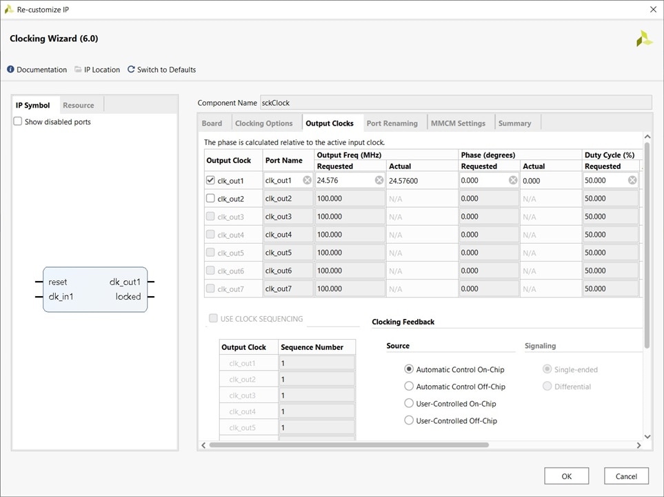
Clocking Wizard generates a Verilog wrapper (module sckClock.v). Here is an extract:
//----------------------------------------------------------------------------
//  Output     Output      Phase    Duty Cycle   Pk-to-Pk     Phase
//   Clock     Freq (MHz)  (degrees)    (%)     Jitter (ps)  Error (ps)
//----------------------------------------------------------------------------
// clk_out1__24.57600______0.000______50.0______598.000____693.818
//
//----------------------------------------------------------------------------
// Input Clock   Freq (MHz)    Input Jitter (UI)
//----------------------------------------------------------------------------
// __primary__________12.000____________0.010

`timescale 1ps/1ps

(* CORE_GENERATION_INFO = "sckClock,clk_wiz_v6_0_9_0_0,{component_name=sckClock,use_phase_alignment=true,use_min_o_jitter=false,use_max_i_jitter=false,use_dyn_phase_shift=false,use_inclk_switchover=false,use_dyn_reconfig=false,enable_axi=0,feedback_source=FDBK_AUTO,PRIMITIVE=MMCM,num_out_clk=1,clkin1_period=83.333,clkin2_period=10.0,use_power_down=false,use_reset=true,use_locked=true,use_inclk_stopped=false,feedback_type=SINGLE,CLOCK_MGR_TYPE=NA,manual_override=false}" *)

module sckClock
 (
  // Clock out ports
  output        clk_out1,
  // Status and control signals
  input         reset,
  output        locked,
 // Clock in ports
  input         clk_in1
 );

  sckClock_clk_wiz inst
  (
  // Clock out ports
  .clk_out1(clk_out1),
  // Status and control signals
  .reset(reset),
  .locked(locked),
 // Clock in ports
  .clk_in1(clk_in1)
  );

endmodule
Now that I have a Verilog module that takes CmodS7’s 12MHz clock as input and outputs a SCK clock at 24.756MHz, I will look at how I can write the whole sound test app. The first module I wrote is oscI2S.v. This takes a 24.756MHz clock as input and outputs the needed BCK and LRCK clocks. (division by 8 and 64). https://github.com/a3333333/Summer-of-FPGA/blob/main/soundTest/cmods7/oscillatorI2S.v
The second module I wrote was a squareWaveGenerator. The hw32 and lw32 registers contain the whole sequence (32 bit) for the high and low levels. (to make things more visible in the simulator I used the value 0x75F5 instead of 0x7FFF for the high level.) To keep things simple, I only send data on the left channel, the right channel stays at 0. https://github.com/a3333333/Summer-of-FPGA/blob/main/soundTest/cmods7/squareWaveGenerator.v
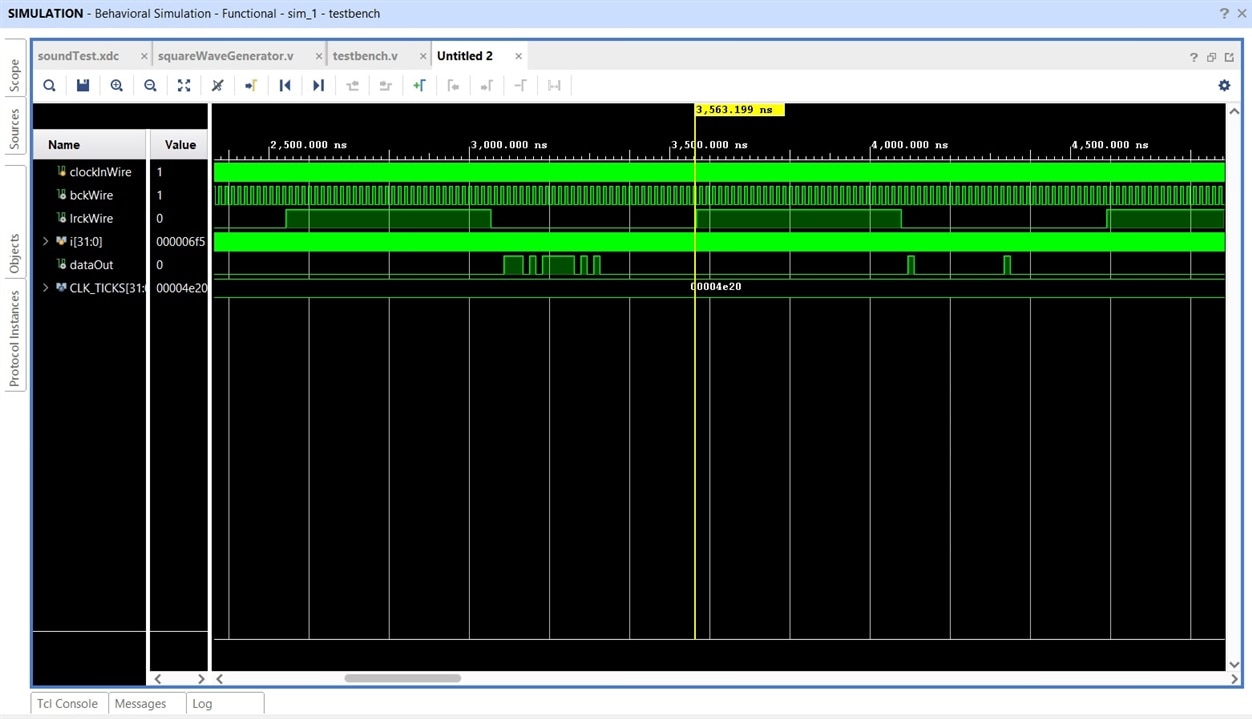
To test the code, I wrote a testbech. https://github.com/a3333333/Summer-of-FPGA/blob/main/soundTest/cmods7/testbench.v Here is the result of the simulation: on the left channel one can see a series of 8 samples (4 samples of high level followed by 4 samples low level). For the simulation I tried various numbers of samples: 8, 16, 20, 30, etc… The code behaved well for all tests, so for the final version of the code I used 120 samples (60 high level + 60 low level) so that the generated pitch will be 400Hz.

Here is a close up where one can see the high level (75F5) and the low level (8001) on the left channel.
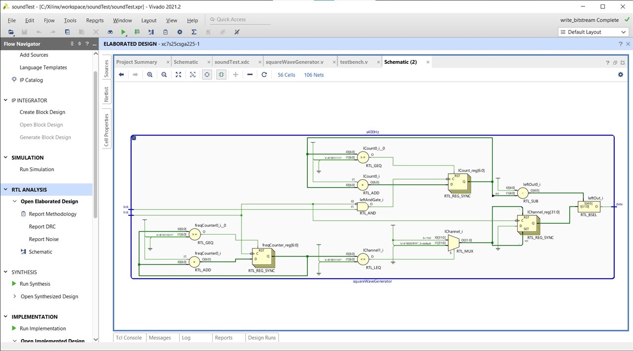
here are a couple of schematics for the implemented design.

Finally, here is a movie where you can hear the 400Hz pitch of the 50% duty square wave:
Github repository:
https://github.com/a3333333/Summer-of-FPGA/tree/main/soundTest
Concepts: Xilinx Clocking Resources, Clock Management Tile, Clocking Wizard, I2S protocol,