Table of Contents
Abstract
This is the final blog for the "Summer of FPGA" challenge.
My aim for this one is to explain most of the technicalities of how the Peripheral is designed and built. At the end of this blog, I would be giving my opinion on the tools I used and the overall experience and skills I have garnered since. I would also like to state and describe some features that I would have liked to have added before the deadline.
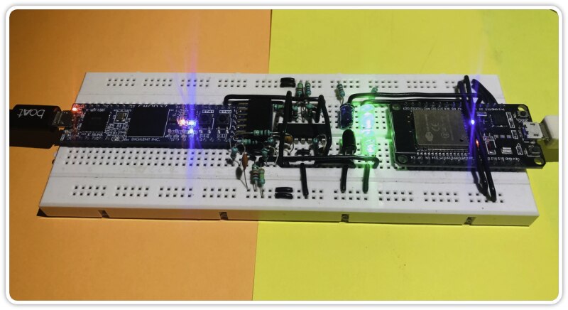
So without any further delay, I give you LiFi in the flesh...
Modules
I divided the whole unwrapping process into separate modules, such that each part of the frame could be processed and on successful execution, the baton (packet) gets passed on to the next module until the STOP.
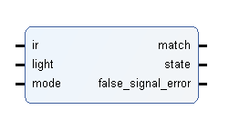
LIR interface
`timescale 1ns / 1ns
// interface to process external digital signal from LiFi frontend

module LIR_interface (
input wire ir,
input wire light,
input wire mode, // to activate match error
output wire match,
output wire state,
output wire false_signal_error // set when match is 0 and mode is 1
    );

    // dataflow assignments --------
    assign match = (ir == light) ? 1 : 0;
    assign state = (light) ? 1 : 0;
    assign false_signal_error = mode & ~match;
    // -----------------------------

endmodule
I called this the L-IR interface because I am using "visible light"[L] AND "infrared light"[IR] as a communication medium. The LIR interface maps the digital signal from the Schmitt trigger to the MATCH and STATE signal, it also has the capability to run in 2 modes:
- mode 0: normal mode; here the STATE signal IS NOT validated via the MATCH signal
- mode 1: monitor mode; here the STATE signal IS validated via the MATCH signal and the false_signal_error flag is raised triggering an ABORT procedure.
During BOUND detection, the interface runs in mode 0, and switches to mode 1 when the actual information needs to be extracted. This prevents any unwanted glitches or external signals from tampering with the packet.
BOUND Detector
`timescale 1ns / 1ns
// START detector module detects the frame/packet start

module BOUND_detector (
input wire clk,
input wire clr,
input wire en,
input wire mode,
input wire match,
input wire state,
output reg next_bat = 1'b0
    );

    // internal variables ---------------
    wire [0:1]current_state;
    wire intermediate;
    wire con_clk;
    wire con_state;
    wire con_clr;
    // ----------------------------------

    // wrapper for sequence detector ----
    sequence_detector #(.X0((2'b01 | 2'b10 << 2 | 2'b11 << 4 | 2'b11 << 6)), .X1((2'b00 | 2'b00 << 2 | 2'b00 << 4 | 2'b00 << 6)), .TRIGGER(1'b1)) wrapper (
    .clk(con_clk),
    .data(con_state),
    .clr(con_clr),
    .result(intermediate),
    .current_state(current_state)
        );
    // ----------------------------------

    // mode function --------------------
    always @(posedge intermediate or posedge clr) begin
        if (clr)
            next_bat <= 0;
        else if (intermediate)
            next_bat <= match & ~next_bat;
    end
    // ----------------------------------

    // connectors on enable ----------
    assign con_clk = en & clk;
    assign con_state = ~mode ^ state;
    assign con_clr = clr | (mode ^ (state == match));
    // ----------------------------------

endmodule
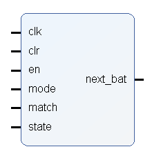
The BOUND detector is capable of detecting both the START and STOP sequence of the signal with the help of the mode control signal. If you have been keeping track of my blogs you will notice my generic sequence detector, It is set to detecting a 0001 sequence, however, you may have noticed that the STOP sequence is different, in fact, it is a complement, so as an optimization I adjusted for it using mode.
This module is a bit different than the others since I am using a wrapper, so I used a few connectors to adjust the signals fed into the sequence detector.
As mentioned earlier, this module runs the interface in mode 0, meaning that the detector has to track the MATCH and STATE signals manually and disable false_signal_error detection.
The BOUND detector mode is used to configure the module to detect either the START or STOP sequence:
- mode 0: START detection; here the STATE must match MATCH otherwise the FSM gets reset.
- mode 1: STOP detection; here the STATE must compliment the MATCH otherwise the FSM gets reset.
Now there is a problem here, specifically the fact that the START and STOP sequence are not ideal and can be triggered unintentionally (but the packet may get aborted later on), changing the sequence itself can help or even better, having variations in MATCH rule can overcome this issue but that would complicate this blog so I removed that code in the end.
The next_bat signal is common among most modules and is a crucial control signal to enable the following/next modules. I did name it as next originally but that is a keyword in HDL so I renamed them to next_bat (stands for next baton).
ID Buffer
`timescale 1ns / 1ns
// ID buffer extracts the device ID from the packet and activates the data length buffer
// this module runs the LIR interface in mode 1

module ID_buf (
input wire clk,
input wire clr,
input wire en,
input wire state,
input wire [0:10]target_id,
input wire load, // to load the target_id into buffer
output wire id_match,
output reg [0:10]received_id = 0,
output wire next_bat
    );

    // internal variables ---------------------
    reg [0:3]counter = 0;
    reg [0:10]target_id_buffer = 0;
    // ----------------------------------------

    // clk events -----------------------------
    always @(posedge clk or posedge clr) begin
        if (clr) begin
            received_id <= 0;
            counter <= 0;
        end
        else if (en & (counter < 11)) begin
            received_id <= {received_id[1:10], state};
            counter <= counter + 1;
        end
    end
    // ----------------------------------------

    // load event -----------------------------
    always @(posedge load) begin
        if (clr) target_id_buffer <= 0;
        else target_id_buffer <= target_id;
    end
    // ----------------------------------------

    // dataflow assignments -------------------
    assign id_match = en & (counter == 11) & (received_id == target_id_buffer);
    assign next_bat = (counter == 11);
    // ----------------------------------------

endmodule
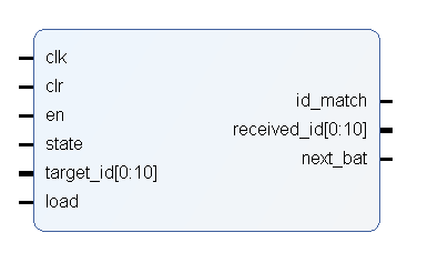
The ID buffer is a port-heavy module, it is used to extract authenticate the ID from the packet. one of the input ports "target_id", requires an expected ID that is used to compare the received ID. If the IDs match then the id_match signal is triggered, however, the next_bat signal is triggered regardless of whether the IDs match or not. The next_bat in this case is used to trigger a load in the received_ID buffer which can be used by the controller to report the false ID. This also future proofs the protocol for when we want to use the RTR or communicate with many devices through some topic or even send over an encryption key if required.
The load port is used to load the target_id into an internal register. The choice of an 11 bit ID simply comes from the fact that I based it off of the CAN protocol.
The module runs the interface in mode 1 to enable false_signal_error, so if MATCH becomes false then the flag is raised and the ABORT sequence is run.
Length Extractor
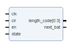
`timescale 1ns / 1ns
// Length extractor module extracts the data length code, this length also includes the CRC
// this module runs the LIR interface in mode 1

module length_extractor (
input wire clk,
input wire clr,
input wire en,
input wire state,
output reg [0:3]length_code = 4'b0,
output wire next_bat
    );

    // internal variables ---------------------
    reg [0:2]counter = 0;
    // ----------------------------------------

    // clk events -----------------------------
    always @(posedge clk or posedge clr) begin
        if (clr) begin
            counter <= 0;
            length_code <= 0;
        end
        else if (en & (counter < 4)) begin
            length_code <= {length_code[1:3], state};
            counter <= counter + 1;
        end
    end
    // ----------------------------------------

    // dataflow assignments -------------------
    assign next_bat = (counter == 4);
    // ----------------------------------------

endmodule
Simply put, it extracts a 4-bit wide length, which gives information about the size of the data in bytes, this size should also include the 2-bytes of the CRC. The length is additionally stored in the status register. This length code is also used by the data field module to run the limiter in its counter.
Data Field
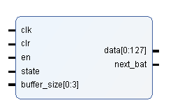
`timescale 1ns / 1ns
// Datafield buffer holds the data along with it CRC, the maximum length is 128bits
// this module runs the LIR interface in mode 1

module datafield (
input wire clk,
input wire clr,
input wire en,
input wire state,
input wire [0:3]buffer_size,
output reg [0:127]data = 128'b0,
output wire next_bat
    );

    // internal variables ---------------------
    reg [0:6]counter = 0;
    // ----------------------------------------

    // clk events -----------------------------
    always @(posedge clk or posedge clr) begin
        if (clr) begin
            data <= 0;
            counter <= 0;
        end
        else if (en & (counter < (buffer_size*8))) begin
            data[counter] <= state;
            counter <= counter + 1;
        end
    end
    // ----------------------------------------

    // dataflow assignments -------------------
    assign next_bat = ~clr & (counter == (buffer_size*8)) & (buffer_size > 2); // to avoid next_bat from triggering if buffer_size is 0
    // ----------------------------------------

endmodule
This module records the data up to the length in bytes and then triggers the next_bat control signal which has a dual purpose in this case of activating the STOP detector and triggering the CRC check. It should be noted that during this stage the state wire is parallelly fed to the CRC block since it needs to compute the CRC itself before applying the check.
CRC XMODEM
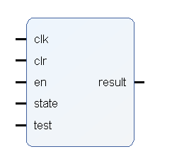
`timescale 1ns / 1ns
// CRC XMODEM module for error detection of received packet
// this module runs the LIR interface in mode 1

module CRC_XMODEM (
input wire clk,
input wire clr,
input wire en,
input wire state,
input wire test,
output wire result
    );

    // internal variable ------------------
    localparam [0:16]generator = 'h11021;
    reg [0:16]target = 0;
    // ------------------------------------

    // clk events -------------------------
    always @(posedge clk or posedge clr) begin
        if (clr) target = 0;
        else if (en) begin
            target = {target[1:16], state};
            if (target[0]) target = target ^ generator;
        end
    end
    // ------------------------------------

    // dataflow assignments ---------------
    assign result = (en & ~clr & test & target == 0)|(result & ~clr) ? 1 : 0;
    // ------------------------------------

endmodule
The way the CRC works is beautifully explained in this Ben Eater video, after learning the basic algorithm I went to the hardware build which was extremely helpful in realizing this module in Verilog.
Essentially the CRC module computes a remainder using the actual data, now if you feed in the correct CRC then the remainder becomes 0, which indicates that your data is intact and therefore contains no errors. In order to get this remainder you also need a CRC quotient which depends on the algorithm you use, it also depends on the initial condition of the internal 16-bit register, however for simplicity's sake I used the XMODEM which uses a 0 initial state and a simple quotient of 0x1021 (you may also notice the extra 1 in the code, that is the overflow bit in the polynomial called x16) that I called the generator.
When the test port goes HIGH, the module returns true for no CRC error and false for a CRC error, which in hindsight is an unnecessary thing to do since I am sending the result to a register to handle the flag anyway, but its too much work redo the wiring at this point (after all, everything was made in a matter of 4 days) and anyway I will be integrating some blocks based on their fields (arbitration, data) in the future to reduce the number of internal registers.
Registers
Registers provide information about the packet and also allow for configuring the peripheral by an external controller, in our case that would be the softcore. We have 4 register modules in total but 8 exposed register ports meaning the controller can interface with 8 registers in total. The reason will be revealed shortly.
Since I was extremely new to IPs, I had to go for a more rusty approach, in the sense that I did not use some features of the FPGA that would make register integration better, and instead went with using the AXI protocol to interface with the softcore.
CONFIG
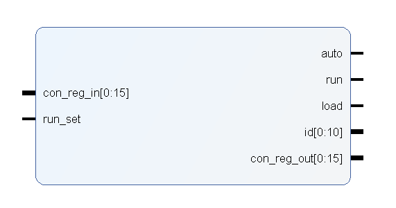
`timescale 1ns / 1ns
// holds the information about the target ID

module config_reg (
input wire [0:15]con_reg_in,
input wire run_set,
output wire auto, run, load,
output wire [0:10]id,
output reg [0:15]con_reg_out
    );

    // initial conditions -------------
    initial begin
        con_reg_out = 0;
    end
    // --------------------------------

    // events -------------------------
    always @(con_reg_in, run) begin
        con_reg_out <= {2'b0, con_reg_in[2], run, con_reg_in[4:15]};
    end
    // --------------------------------

    // dataflow assignments -----------
    assign run = con_reg_in[3] & run_set;
    assign auto = con_reg_in[2];
    assign id = con_reg_in[5:15];
    assign load = con_reg_in[4];
    // --------------------------------

endmodule

Here AUTO stands for auto-reload, as in the run bit is set after every completed received. When RUN is set then the START detector is activated and the reception service begins, this is reset on a complete receive as long as AUTO is 0. The LOAD bit is used to load the TARGET ID which is used by the ID buffer module. The size of this register is 16 bits.
STATUS
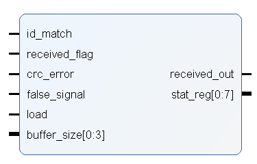
`timescale 1ns / 1ns
// holds the information about the internal state of the LiFi block

module status_reg (
input wire id_match,
input wire received_flag,
input wire crc_error,
input wire false_signal,
input wire load,
input wire reset,
input wire [0:3]buffer_size,
output wire received_out,
output reg [0:7]stat_reg
    );

    // initial conditions -------------
    initial begin
        stat_reg = 0;
    end
    // --------------------------------

    // events -------------------------
    always @(posedge load or posedge reset) begin
        if (reset)
            stat_reg <= 8'b0;
        else
            stat_reg <= {id_match, received_flag, crc_error, false_signal, buffer_size};
    end
    // --------------------------------

    // dataflow assignments -----------
    assign received_out = received_flag;
    // --------------------------------

endmodule

This is an 8-bit register that stores information about the packet properties like:
- ID match: HIGH when the received ID matches the target ID
- Received Flag: HIGH when the packet is received and must be reset by the controller
- CRC error: is HIGH when there is a CRC error
- False Signal Error: This is set by the interface during mode 1 operation.
- Length Code: length of the received data (inc. 2bytes of CRC) in bytes.
The module also presents a convenient RESET port to reset all the flags for the next packet reception. The LOAD port is used internally by the peripheral to load the value of the flags which is strategically triggered depending on the type of error.
The received_out signal is used internally in the peripheral, to clear certain modules.
RECEIVED ID
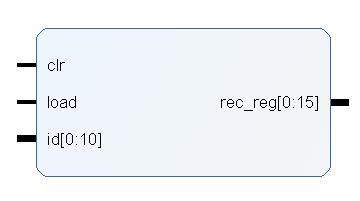
`timescale 1ns / 1ns
// holds the received ID in 16 bit wide register

module received_id_reg (
input wire clr,
input wire load,
input wire [0:10]id,
output reg [0:15]rec_reg
    );

    // initial conditions -------------
    initial rec_reg = 0;
    // --------------------------------

    // events -------------------------
    always @(posedge load or posedge clr) begin
        if (load) begin
            rec_reg <= {5'b0, id};
        end
        else if (clr) begin
            rec_reg <= 0;
        end
    end
    // --------------------------------

endmodule

This is buffer solely meant to hold the received ID for reference, to standardize the size I made is 16 bits wide with 5 bits in the MSB being non-informative.
DATA SPLITTER
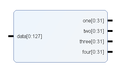
`timescale 1ns / 1ns
// Field Splitter divides the 128 bit wide data field into 4x 32 bit wide vectors for the AXI GPIO

module field_splitter (
input wire [0:127] data,
output wire [0:31] one,
output wire [0:31] two,
output wire [0:31] three,
output wire [0:31] four
    );

    // dataflow assignments ----------
    assign one = data[0:31];
    assign two = data[32:63];
    assign three = data[64:95];
    assign four = data[96:127];
    // -------------------------------

endmodule
The 128-bit wide data field is incompatible with the 32 bit limit of the AXI GPIOs, therefore I made a splitter module that presents the 128 bits in 4 channels = [one, two, three, four]. The naming convention is purely preferential.
Peripheral Assembly
Now comes the most difficult part, initially I had assembled the peripheral in block design, however, the update hierarchy issue mentioned in blog #4 forced me to assemble it manually in Verilog. This may seem like a horrible idea at first BUT it was very easy and a lot better than the block editor. For one, the synthesis of the peripheral alone took just under 30 seconds compared to nearly 45 minutes in block. Secondly, It forced me to arrange the code in a very orderly manner as you will see soon, giving me a birds-eye view of the circuit without the whole ratsnest. Another advantage was the use of primitives was made easier using Verilog assignments and implementing latches was also a major boon in this method.
The LiFi Peripheral module block and code is below:
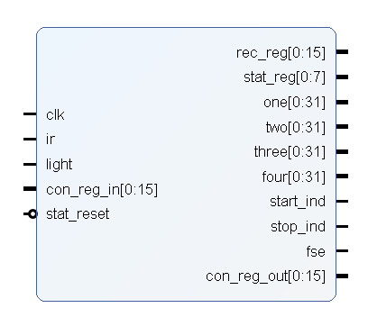
`timescale 1ns / 1ns
// block module for LiFi peripheral

module LiFi_Peripheral (
// input ports -------
input wire clk,
input wire ir, light,
input wire [0:15]con_reg_in, // config write-only register
input wire stat_reset, // to reset the status register
// -------------------
// output ports ------
output wire [0:15]rec_reg, // received id register
output wire [0:7]stat_reg, //status register

output wire [0:31]one,
output wire [0:31]two,
output wire [0:31]three, // datafield split register
output wire [0:31]four,

output wire start_ind, stop_ind, fse, // (optional indicator wires)

output wire [0:15]con_reg_out // config read-only register
// -------------------
    );

    // internal wires ----------
    wire match, state, false_signal_error, lir_mode; // from interface
    wire common_clr; // clr common to bounding, id, and length
    wire start_en, next_bat_from_start; // from start detector

    // ++++++++++ from id buffer ++++++++++
    wire [0:10]target_id;
    wire id_match, id_buffer_en, next_bat_from_id_buffer;
    wire [0:10]received_id;
    // ++++++++++++++++++++++++++++++++++++

    // ++++++++++ from length extractor ++++++++++
    wire [0:3]length_code;
    wire length_extractor_en, next_bat_from_length_extractor;
    // +++++++++++++++++++++++++++++++++++++++++++

    // +++++++++ from received register +++++++++
    reg rec_reg_load;
    // ++++++++++++++++++++++++++++++++++++++++++

    // +++++++++ from status register +++++++++++
    wire crc_error, received_out_feedback;
    reg stat_load;
    // ++++++++++++++++++++++++++++++++++++++++++

    reg pre_clr; // clr for datafield and CRC
    wire [0:127]data; // from data field
    wire crc_result; // from CRC XMODEM
    wire next_bat_from_stop; // from stop detector

    wire run, config_load, auto, run_set; // from configuration register
    // -------------------------

    // LIR interface connections -------
    LIR_interface interface (
    .ir(ir),
    .light(light),
    .mode(lir_mode),
    .match(match),
    .state(state),
    .false_signal_error(false_signal_error)
        );
    // ---------------------------------

    // Bound Detector START ------------
    BOUND_detector start_detector (
    .clk(clk),
    .clr(common_clr),
    .en(start_en),
    .mode(1'b1),
    .match(match),
    .state(state),
    .next_bat(next_bat_from_start)
        );
    // ---------------------------------

    // ID Buffer -----------------------
    ID_buf id_buffer (
    .clk(clk),
    .clr(common_clr),
    .en(next_bat_from_start),
    .state(state),
    .target_id(target_id),
    .load(config_load),
    .id_match(id_match),
    .received_id(received_id),
    .next_bat(next_bat_from_id_buffer)
        );
    // ---------------------------------

    // Length Extractor ----------------
    length_extractor length_extractor_mod (
    .clk(clk),
    .clr(common_clr),
    .en(next_bat_from_id_buffer),
    .state(state),
    .length_code(length_code),
    .next_bat(next_bat_from_length_extractor)
        );
    // ---------------------------------

    // DataField -----------------------
    datafield datafield_mod (
    .clk(clk),
    .clr(pre_clr),
    .en(next_bat_from_length_extractor),
    .state(state),
    .buffer_size(length_code),
    .data(data),
    .next_bat(next_bat_from_datafield)
        );
    // ---------------------------------

    // CRC XMODEM ----------------------
    CRC_XMODEM crc_check (
    .clk(clk),
    .clr(pre_clr),
    .en(next_bat_from_length_extractor),
    .state(state),
    .test(next_bat_from_datafield),
    .result(crc_result)
        );
    // ---------------------------------

    // Bound Detector STOP -------------
    BOUND_detector stop_detector (
    .clk(clk),
    .clr(common_clr),
    .en(next_bat_from_datafield),
    .mode(1'b0),
    .match(match),
    .state(state),
    .next_bat(next_bat_from_stop)
        );
    // ---------------------------------

    // REGISTERS =================================
    // Configuration Register ---
    config_reg config_reg_mod (
    .con_reg_in(con_reg_in),
    .run_set(run_set),
    .auto(auto),
    .run(run),
    .load(config_load),
    .id(target_id),
    .con_reg_out(con_reg_out)
        );
    // --------------------------

    // Status Register ----------
    status_reg status_reg_mod (
    .id_match(id_match),
    .received_flag(next_bat_from_stop),
    .crc_error(crc_error),
    .false_signal(false_signal_error),
    .load(stat_load),
    .reset(stat_reset),
    .buffer_size(length_code),
    .received_out(received_out_feedback),
    .stat_reg(stat_reg)
        );
    // --------------------------

    // received ID buffer -------
    received_id_reg received_id_reg_mod (
    .clr(pre_clr),
    .load(rec_reg_load),
    .id(received_id),
    .rec_reg(rec_reg)
        );
    // --------------------------

    // Field Splitter -----------
    field_splitter splitter (
    .data(data),
    .one(one),
    .two(two),
    .three(three),
    .four(four)
        );
    // --------------------------
    // ===========================================

    // dataflow assignments ----------------------------
    assign start_en = run ^ next_bat_from_start;
    assign lir_mode = ~(start_en | next_bat_from_datafield);
    assign crc_error = ~crc_result;
    assign run_set = auto | ~next_bat_from_stop;
    assign common_clr = (received_out_feedback | (~id_match & next_bat_from_id_buffer)) & ~clk;

    assign start_ind = next_bat_from_start; //
    assign stop_ind = next_bat_from_stop;	// ignore debug wires
    assign fse = ~false_signal_error;		//
    // -------------------------------------------------

    // timed events ------------------------------------
    always @(posedge clk) pre_clr <= (next_bat_from_start | false_signal_error) ^ next_bat_from_id_buffer;
    always @(negedge clk) stat_load <= next_bat_from_stop;
    always @(next_bat_from_id_buffer) rec_reg_load <= next_bat_from_id_buffer;
    // -------------------------------------------------

endmodule
As you can see I divided the code using a few code fences and mostly arranged the whole thing with regards to the de-framing process. I also kept a few indicator wires hooked up to the CMOD S7's onboard LEDs for debugging purposes, since at that time I was running this at a staggering slow speed of 10Hz to observe what was happening.
I spent most of the time tuning the timed events and dataflow assignments, so in reality, it was just that part of the code that was my concern, which is great because reading this gargantuan is a pain in the neck (literally).
I would love to explain all the connections but that would take a lot of time, so instead, I will explain only the necessary signals along with the general connection rule.
Essentially the next_bat signals connect to the enables of the following blocks, for example, after the START detector the next_bat_from_start wire connects to the enable port of the ID buffer and so forth.
The start_en signal enables the start sequence and depends on the run signal that comes from the run flag from the CONFIG register processed through some logic to prevent concurrent writes from the controller and the peripheral itself, as suggested earlier the controller can change some register flags itself.
The lir_mode wire coordinates the mode the interface would have to run in.
As discussed earlier, the crc_error has some unnecessary logic that I would like to remove, but in adherence to the rules of the challenge, I won't.
run_set prevents the peripheral from resetting the run flag if AUTO mode is enabled in the CONFIG register.
Two of the most coordinated signals are the common_clr and pre_clr signals. The common_clr clears most of the modules after the STOP sequence is detected, whereas the pre_clr signal is used to clear the modules that have registers associated with them, as the data field. We also have some load wires to load the registers.
There were some concurrency errors initially but most of them seem to be fixed, through several simulation runs.
Simulation Testbenches
One of the key factors to completing the project was replacing hardware testing with simulations. That's not to say that I completely let go of hardware testing, but since I would have to create separate ESP32 test benches for them I decided to instead focus on building comprehensive simulation test benches.
I tested the LIR interface through hardware since it was the easiest and then all the rest were done through simulations.
ID test
the ID testbench was used to test the ID buffer.
`timescale 1ns / 1ns
// ID buffer test bench

module ID_test;

// variables ----------------
integer counter;

reg clk = 1'b0;
reg clr = 1'b0;
reg en = 1'b0;
reg mode = 1'b1;
reg [0:10]target_id = 11'b01000110100;
reg load = 1'b0;

reg ir;
reg light;

wire match;
wire state;
wire error;

wire id_match;
wire [0:10]received_id;
wire next;

reg [0:10]sample = 11'b01000110101;
// --------------------------

// create the wrappers ------
LIR_interface interface (
.ir(ir),
.light(light),
.mode(mode),
.match(match),
.state(state),
.false_signal_error(error)
    );
ID_buf wrapper (
.clk(clk),
.clr(clr),
.en(en),
.state(state),
.target_id(target_id),
.load(load),
.id_match(id_match),
.received_id(received_id),
.next_bat(next)
);
// --------------------------

// setup initial ------------
initial begin
    // clear momentarily
    #2 clr = 1'b1;
    #2 clr = 1'b0;

    // set the enable pin
    #1 en = 1'b1;

    // load the target id
    load = 1'b1;
    #1 load = 1'b0;

    // display the test signal
    $display("----------------------------");
    $display("SAMPLE = %11b", sample);

    // send the bit sequence
    for (counter = 0; counter < 11; counter = counter + 1) begin
        #1 {light, ir} = {sample[counter], sample[counter]};
        #1 clk = ~clk;
        #2 clk = ~clk;
    end

    // clear
    #2 clr = 1'b1;
    #1 clr = 1'b0;

    $display("------------END-------------");
end
// --------------------------

endmodule
Length test
This was used to test the length extractor module.
`timescale 1ns / 1ns
// Data length code test bench

module length_test;

// variables ----------------
integer counter;

reg clk = 1'b0;
reg clr = 1'b0;
reg en = 1'b0;
reg mode = 1'b1;

reg ir;
reg light;

wire match;
wire state;
wire error;

wire [0:3]length_code;
wire next;

reg [0:3]sample = 4'b1011;
// --------------------------

// create the wrappers ------
LIR_interface interface (
.ir(ir),
.light(light),
.mode(mode),
.match(match),
.state(state),
.false_signal_error(error)
    );
length_extractor wrapper (
.clk(clk),
.clr(clr),
.en(en),
.state(state),
.length_code(length_code),
.next(next)
    );
// --------------------------

// setup initial ------------
initial begin
    // clear momentarily
    #2 clr = 1'b1;
    #2 clr = 1'b0;

    // set the enable pin
    #1 en = 1'b1;

    // display the test signal
    $display("----------------------------");
    $display("SAMPLE = %4b", sample);

    // send the bit sequence
    for (counter = 0; counter < 4; counter = counter + 1) begin
        #1 {light, ir} = {sample[counter], sample[counter]};
        #1 clk = ~clk;
        #2 clk = ~clk;
    end

    // clear
    #2 clr = 1'b1;
    #1 clr = 1'b0;

    // disable
    en = 1'b0;

    $display("------------END-------------");
end
// --------------------------

endmodule
BOUND test
This was used to test the BOUND detector.
`timescale 1ns / 1ns
// BOUND detector test bench

module BOUND_test;

// variables ----------------
integer counter;

reg clr = 1'b0;
reg clk = 1'b0;
reg mode = 1'b0;
reg en = 1'b0;
reg match = 1'b0;
reg state = 1'b0;
wire next_bat;

reg [0:63]match_sample = 64'b0001100001100101011011000110110001101111001000011000101001100001;
reg [0:63]state_sample = 64'b1110001001000010001010001011001010110100000101010010000101010001;
// --------------------------

// create the wrapper -------
BOUND_detector wrapper (
.clk(clk),
.clr(clr),
.en(en),
.mode(mode),
.match(match),
.state(state),
.next_bat(next_bat)
    );
// --------------------------

// setup initial ------------
initial begin
    // clear momentarily
    #2 clr = 1'b1;
    #2 clr = 1'b0;

    // display the test signal
    $display("----------------------------");
    $display("MATCH SAMPLE = %64b", match_sample);
    $display("STATE SAMPLE = %64b", state_sample);

    // select the mode (START/STOP)
    mode = 1'b1;

    // enable operation
    en = 1'b1;

    // random concurrent clear command
    clr <= #80 1;
    clr <= #90 0;

    // register bit sequence
    for (counter = 0; counter < 64; counter = counter + 1) begin
        #2 {match, state} = {match_sample[counter], state_sample[counter]};
        #1 clk = ~clk;
        #2 clk = ~clk;
    end

    // disable operation
    en = 1'b0;

    $display("------------END-------------");
end
// --------------------------

endmodule
CRC test
This was interesting because it worked on the first try, but it tests the CRC XMODEM module.
`timescale 1ns / 1ns
// CRC test bench

module CRC_test;

// variables ----------------
integer counter;

reg clk = 1'b0;
reg clr = 1'b0;
reg state = 1'b0;
reg en = 1'b0;
reg test = 1'b0;

wire result;

reg [0:63]sample = 64'b0100100001100101011011000110110001101111001000011000101001100100;
// --------------------------

// create the wrapper -------
CRC_XMODEM wrapper (
.clk(clk),
.clr(clr),
.en(en),
.state(state),
.test(test),
.result(result)
    );
// --------------------------

// setup initial ------------
initial begin
    // clear momentarily
    #2 clr = 1'b1;
    #2 clr = 1'b0;

    // set the enable pin
    #1 en = 1'b1;

    // display the test signal
    $display("----------------------------");
    $display("SAMPLE = %64b", sample);

    // register the sequence
    for (counter = 0; counter < 64; counter = counter + 1) begin
        #1 state = sample[counter];
        #1 clk = ~clk;
        #2 clk = ~clk;
    end

    // trigger the test pin
    test = 1'b1;
    #4 test = 1'b0;

    // clear the result
    #10 clr = 1'b1;
    #2 clr = 1'b0;

    $display("------------END-------------");
end
// --------------------------

endmodule
Datafield test
The data field test was kind of unnecessary, but I did have some issue earlier that was resolved in the peripheral assignments.
`timescale 1ns / 1ns
// DataField test bench

module datafield_test;

// variables ----------------
integer counter;

reg clk = 1'b0;
reg clr = 1'b0;
reg state = 1'b0;
reg en = 1'b0;
reg [0:3]buffer_size = 5; // 5 bytes

wire [0:127]data;
wire next;

reg [0:63]sample = 64'b1100100001100101011011000110110001101111001000011000101001100101;
// --------------------------

// create the wrapper -------
datafield wrapper (
.clk(clk),
.clr(clr),
.en(en),
.state(state),
.buffer_size(buffer_size),
.data(data),
.next(next)
    );
// --------------------------

// setup initial ------------
initial begin
    // clear momentarily
    #2 clr = 1'b1;
    #2 clr = 1'b0;

    // set the enable pin
    #1 en = 1'b1;

    // display the test signal
    $display("----------------------------");
    $display("SAMPLE = %64b", sample);

    // register the sequence
    for (counter = 0; counter < 64; counter = counter + 1) begin
        #1 state = sample[counter];
        #1 clk = ~clk;
        #2 clk = ~clk;
    end

    // clear the result
    #10 clr = 1'b1;
    #2 clr = 1'b0;

    // disable operation
    en = 1'b0;

    $display("------------END-------------");
end
// --------------------------

endmodule
Full Block test
This was the big and most important one, with nearly 50+ internal signals. Here is the waveform:
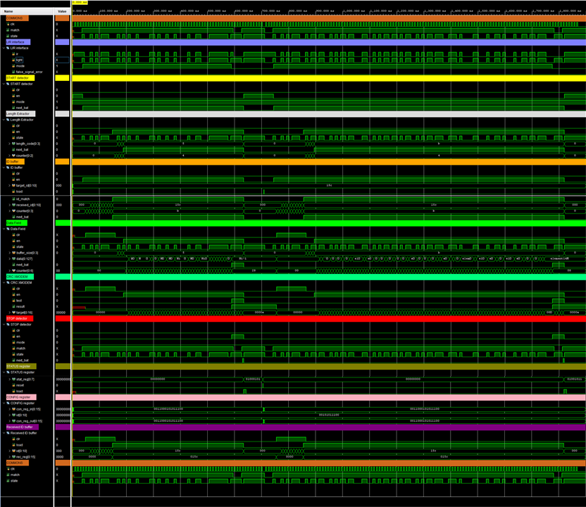
Yup... hours and hours of looking at this abomination
Anyyyyway...
Here is the testbench code:
`timescale 1ns / 1ns
// test bench for full LiFi design

module full_block_test;

// variables ----------------
integer counter;

reg clk = 1'b0;

reg [0:54]first = 55'b0010101110001010100100001101001001000010011000111111101;
reg [0:102]second = 103'b0010101110010110110010101101100011001010110110101100101011011100111010000110001001101000100110110111000;
reg [0:3]start_stop_sequence = 4'b0001;
reg [0:10]target_id_one = 11'b00101011100;
reg [0:10]target_id_two = 11'b00101011100;

reg [0:15]con_reg_in = 0;
wire [0:15]con_reg_out = 0;
wire [0:15]received_id;
wire [0:7]stat_reg;

wire [0:127]data;

reg ir, light;
reg stat_reset = 0;
// --------------------------

// create the wrapper -------
LiFi_Peripheral wrapper(
.clk(clk),
.ir(ir),
.light(light),
.con_reg_in(con_reg_in),
.stat_reset(stat_reset),
.rec_reg(received_id),
.stat_reg(stat_reg),
.one(data[0:31]),
.two(data[32:63]),
.three(data[63:95]),
.four(data[95:127]),
.con_reg_out(con_reg_out)
    );
// --------------------------

// setup initial ------------
initial begin
    // display the test signal
    $display("----------------------------");
    $display("FIRST PACKET = %55b", first);
    $display("SECOND PACKET = %103b", second);
    $display("TARGET ID = %11b", target_id_one);
    $display("TARGET ID = %11b", target_id_two);
    $display("START STOP SEQUENCE = %4b", start_stop_sequence);

    // configure
    #2 con_reg_in = {2'b0, 1'b1, 1'b1, 1'b1, target_id_one};
    #2 con_reg_in[4] = 0;

    // start sequence
    for (counter = 0; counter < 4; counter = counter + 1) begin
        #2 {ir, light} = {1'b1, start_stop_sequence[counter]};
        #3 clk = ~clk;
        #5 clk = ~clk;
    end

    // register bit sequence
    for (counter = 0; counter < 55; counter = counter + 1) begin
        #2 {ir, light} = {first[counter], first[counter]};
        #3 clk = ~clk;
        #5 clk = ~clk;
    end

    // stop sequence
    for (counter = 0; counter < 4; counter = counter + 1) begin
        #2 {ir, light} = {1'b0, ~start_stop_sequence[counter]};
        #3 clk = ~clk;
        #5 clk = ~clk;
    end

    // reset
    light = 1;
    ir = 1;

    $display("first trasnmission completed at %t", $time);

    // wait for 7 bit cycles
    for (counter = 0; counter < 14; counter = counter + 1) #5 clk = ~clk;

    // trigger stat reset
    #1 stat_reset = 1;
    #1 stat_reset = 0;

    // configure
    #2 con_reg_in = {2'b0, 1'b1, 1'b1, 1'b1, target_id_two};
    #2 con_reg_in[4] = 0;

    $display("next transmission starts at %t", $time);

    // send the next message
    // start sequence
    for (counter = 0; counter < 4; counter = counter + 1) begin
        #2 {ir, light} = {1'b1, start_stop_sequence[counter]};
        #3 clk = ~clk;
        #5 clk = ~clk;
    end

    $display("datafield second register starts at %t", $time);

    // register bit sequence
    for (counter = 0; counter < 103; counter = counter + 1) begin
        #2 {ir, light} = {second[counter], second[counter]};
        #3 clk = ~clk;
        #5 clk = ~clk;
    end

    // stop sequence
    for (counter = 0; counter < 4; counter = counter + 1) begin
        #2 {ir, light} = {1'b0, ~start_stop_sequence[counter]};
        #3 clk = ~clk;
        #5 clk = ~clk;
    end

    // reset
    light = 1;
    ir = 1;

    // run the clock a little more
    for (counter = 0; counter < 10; counter = counter + 1) #5 clk = ~clk;

    $display("------------END-------------");
end
// --------------------------

endmodule
Hmmm sooooo...
ESP32 testbench
So to test the LiFi peripheral completely assembled I had to setup a transmitter, and that's exactly what I did. You can find the code on my GitHub repo here. The code is pretty straightforward with prompts to enter the message. The only IO connection is to the LEDs and that's pretty much it.
Integration w/ MicroBlaze SoftCore
Finally, we need to pair the LiFi peripheral with a controller, and here is where the MicroBlaze IP comes in. As suggested earlier, I am new to using IPs like so but with the help of yesha98 and navadeepganeshu I was able to figure out a solution to it. The C code was not much of an issue other than the fact that I opted to not use Interrupts and instead rely on polling, which is not ideal but TBH the documentation for it was quite fragmented and I had a few hours remaining before the deadline soooo... polling it was.
I connected all the register outputs to the AXI GPIOs configuring them as required (input/output, bit length). I also added the generic clk_divider from blog #2 to run the slow bitrate for the experiment. I initially set it up for 10Hz then 100Hz and then 200Hz.
I also added the UART IP and exposed a few external ports for debugging purposes.
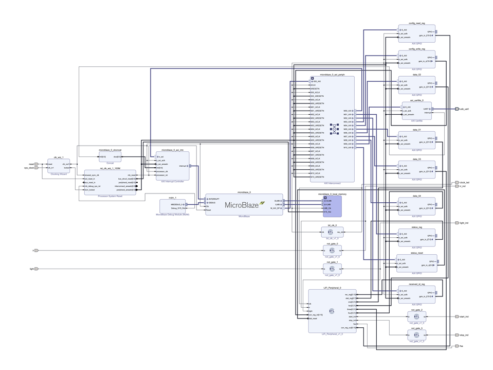
You know the drill by now, SIMP!
and then export the hardware.
Vitis Demo
I have to be honest here, I hate Vitis, I really do. It's infuriating how much of a downgrade this seems to SDK and I used SDK after using Vitis.
Regardless, I set up the unfortunate workspace and created an application project from the exported XSA file which also packages the bitstream. Then I followed through with the polling-based code:
// INCLUDES ======================
#include <stdio.h>
#include <stdlib.h>

#include "platform.h"
#include "xil_printf.h"

// for AXI GPIOs
#include "xgpio.h"
#include "xparameters.h"

// for delay
#include "sleep.h"
// ===============================

// GLOBAL VARS ===================
// declare XGPIO objects
XGpio status_reg;
XGpio status_reset;
XGpio config_writeonly_reg;
XGpio config_readonly_reg;
XGpio received_ID_reg;
XGpio data_reg[4];

// variables to hold the register data
u8 status;
u16 received_id;
u16 config;
u32 data[4];
// ===============================


// HELPER FUNCTIONS ====================
// to read the status register
void readStatus() {
	status = XGpio_DiscreteRead(&status_reg, 1);
}

// to read the configuration register
void readConfig() {
	config = XGpio_DiscreteRead(&config_readonly_reg, 1);
}

// to read received ID register
void readReceivedID() {
	received_id = XGpio_DiscreteRead(&received_ID_reg, 1);
}

// to reset the status register
void resetStatusRegister() {
	XGpio_DiscreteWrite(&status_reset, 1, 1);
	usleep(5);
	XGpio_DiscreteWrite(&status_reset, 1, 0);
}

// get the data from the buffers
void getData() {
	for (int i=0; i<4; ++i)
		data[i] = XGpio_DiscreteRead(&data_reg[i], 1);
}
// =====================================


int main() {
	// start platform
	init_platform();


	// Welcome screen
	print("\r\n================== LiFi Demo ==================\r\n");


	// ========================= INITIALIZE REGISTERS =========================
	// Initialize the status register and status reset
	XGpio_Initialize(&status_reg, XPAR_STATUS_REG_DEVICE_ID);
	XGpio_Initialize(&status_reset, XPAR_STATUS_RESET_DEVICE_ID);

	// Initialize the configuration registers
	XGpio_Initialize(&config_readonly_reg, XPAR_CONFIG_READ_REG_DEVICE_ID);
	XGpio_Initialize(&config_writeonly_reg, XPAR_CONFIG_WRITE_REG_DEVICE_ID);

	// Initialize the received ID register
	XGpio_Initialize(&received_ID_reg, XPAR_RECEIVED_ID_REG_DEVICE_ID);

	// Initialize the data registers
	XGpio_Initialize(&data_reg[0], XPAR_DATA_01_DEVICE_ID);
	XGpio_Initialize(&data_reg[1], XPAR_DATA_02_DEVICE_ID);
	XGpio_Initialize(&data_reg[2], XPAR_DATA_03_DEVICE_ID);
	XGpio_Initialize(&data_reg[3], XPAR_DATA_04_DEVICE_ID);
	// ========================================================================


	// ========================= SET DATA DIRECTION ===========================
	// inputs
	XGpio_SetDataDirection(&status_reg, 1, 0xFF);
	XGpio_SetDataDirection(&config_readonly_reg, 1, 0XFFFF);
	XGpio_SetDataDirection(&received_ID_reg, 1, 0xFFFF);
	for (int i=0; i<4; ++i)
		XGpio_SetDataDirection(&data_reg[i], 1, 0xFFFFFFFF);

	// outputs
	XGpio_SetDataDirection(&status_reset, 1, 0);
	XGpio_SetDataDirection(&config_writeonly_reg, 1, 0X0000);
	// ========================================================================

	// configure the peripheral to operate in AUTO mode
	resetStatusRegister();
	XGpio_DiscreteWrite(&config_writeonly_reg, 1, 0x395C);
	readConfig();
	xil_printf("Configuration Register Set To %04x\r\n", config);

	// start loop for polling
	while (1) {
		readStatus();

		if (status & 0x40) { // if received triggered
			u8 length = 0x0F & status;
			xil_printf("STATUS register: %02x\r\n", status);
			xil_printf("DATALENGTH: %d\r\n", length);

			readReceivedID();
			xil_printf("RECEIVED ID: %04x\r\n", received_id);

			getData();
			xil_printf("DATA buffer: %08x %08x %08x %08x\r\n", data[0], data[1], data[2], data[3]);
			for (int i=0, j=-1; i<(length-1); ++i) {
				if ((i % 4) == 0)
					++j;
				xil_printf("%c", (char)((data[j] & (0xFF << (8 * ((3-i%4))))) >> (8 * (3-(i%4)))));
			}
			print("\r\n\r\n");

			resetStatusRegister();
		}
	}


	// conclude platform
	cleanup_platform();
	return 0;
}
This is essentially the only piece of code I did modify after the deadline, this is because the original demo would only show the first data field register and it wouldn't even translate it to ASCII, which doesn't make for a good demo. This one on the other hand is much better, reporting all the necessary information about the peripheral. It would have been better with the ISR (Interrupt Service Routine) but I digress.
An important note, the softcore block must be configured with large code memory for this demo to work, this is because the xil_printf library has a larger memory requirement, and I learnt that the hard way.
The demo:
Conclusion & Thoughts
It's been a journey and a great one!
It's satisfying to see the device work as intended and the upgrade in skill ever since I received this beautiful board is truly amazing. I learned more from those 4 days than I did during my entire semester. I know of a lot of potential upgrades to this project but I am happy with what I have done.
My plan was to make a custom peripheral and I did it, that is the UNIQUE capability of FPGAs after all.
The CMOD S7 is a brilliant board to start with HDL, in fact, I never went out of bounds with this board, something that is often the case with other development MCU boards. The size is perfect for travel and just so darn cute!
Xilinx's tools have been great for the most part, better than ModelSim, and heck way better than using Icarus with GTKWave, however, the version of Vitis (2020.1) I used was far from perfect, in fact, there were so many delays during those 4 days due to the non-integration of Vitis, every time there was a change in the hardware, I would have to rebuild the application project again. I hadn't found any other alternative other than just rolling back to an earlier version of the software suite with Xilinx SDK.
I have a lot to say about Vitis, mostly (only) negative. Regardless I want to thank the element14 community for hosting a celebration to the world FPGAs and giving me this wonderful opportunity.
I also want to thank @navadeep and @yesh for guiding me through problems, and dealing with my constant ramblings .
Until next time!
BuBye

-

kluivertcorreia
-
Cancel
-
Vote Up
0
Vote Down
-
-
Sign in to reply
-
More
-
Cancel
Comment-

kluivertcorreia
-
Cancel
-
Vote Up
0
Vote Down
-
-
Sign in to reply
-
More
-
Cancel
Children