Introduction
In this blog post, I will finalize my design of the remote patient monitoring system for the Summer of Sensor Design challenge. My system consists of two units. One is a wearable unit for collecting user activity and sleep quality. The unit was completed in blog #5. Another unit is the main unit that collects the user's heart rate, oxygen saturation, and ECG data. At the same time, it collects the data from the wearable unit and shows all information on a display. It also uploads the data to the cloud server for remote analysis and visualization. For the main unit, two microcontrollers are used. One is Arduino Uno SMD included in the kit. Another microcontroller I used is an ESP8266-based Wemos D1 Mini for displaying the data and uploading the data to the cloud.
Components used in this Unit
Here is the list of the components I used for the main unit.
| {tabbedtable}Components | Description |
|---|---|
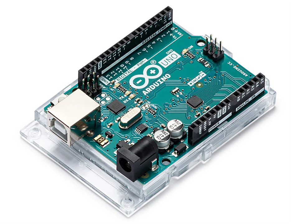
| Arduino Uno SMD |
The Oximeter 5 Click and ECG sensor module is connected to the Arduino UNO SMD through Mikroe Click Shield.
Arduino Uno SMD Official Link: https://store.arduino.cc/products/arduino-uno-rev3-smd |
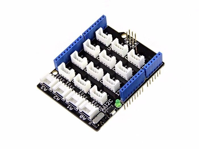
| Grove Base Shield |
Base Shield provides a simple way to connect with Arduino boards and helps you get rid of breadboard and jumper wires. This shield is used here for connecting Wemos D1 mini with the Arduino through UART.
Official link: https://www.seeedstudio.com/Base-Shield-V2.html |
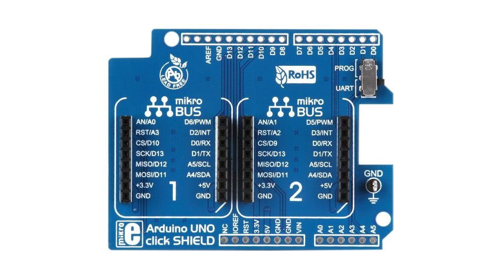
| Arduino Uno click shield |
Arduino Uno click shield is an extension for Arduino Uno and any other Arduino-compatible board. It's a simple shield with two mikroBUS
Details of the shield: https://www.mikroe.com/arduino-uno-click-shield |
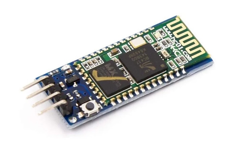
| HC-05 Bluetooth Module |
The HC-05 is a popular module that can add two-way (full-duplex) wireless functionality to any electronic project. You can use this module to communicate between two microcontrollers like Arduino or communicate with any device with Bluetooth functionality like a Phone or Laptop. There are many android applications that are already available which makes this process a lot easier. The module communicates with the help of UART at 9600 baud rate hence it is easy to interface with any microcontroller that supports UART. This module can be configured to operate as Master or Slave mode. I am using it as a slave device for the main unit.
Details of the module: https://howtomechatronics.com/tutorials/arduino/arduino-and-hc-05-bluetooth-module-tutorial/ |
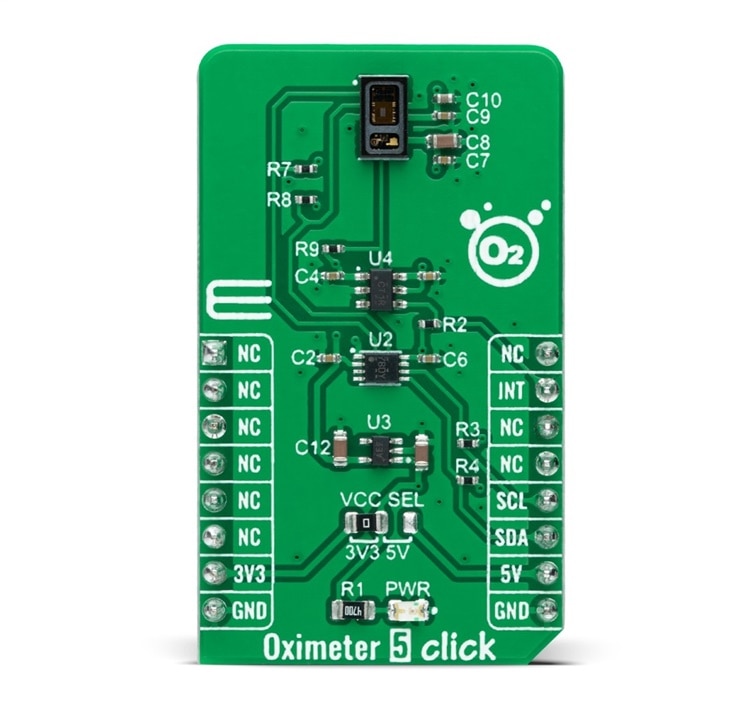
| Oximeter 5 Click |
Oximeter 5 Click as its foundation uses the MAX30102, a high-sensitivity pulse oximeter and heart-rate sensor from Maxim Integrated, now part of Analog Devices. The MAX30102 integrates Red and IR LEDs, with 660nm red and 880nm IR wavelengths, to modulate LED pulses for oxygen saturation (SpO2) and heart rate measurements.
Details can be found here: https://www.mikroe.com/oximeter-5-click |
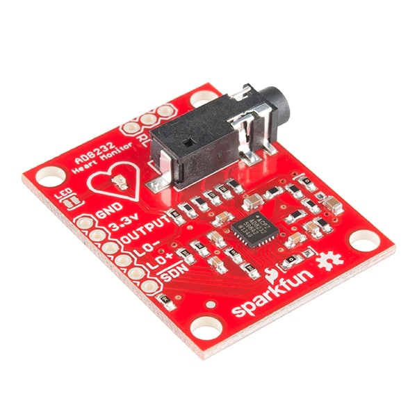
| AD8232 ECG Module |
The AD8232 SparkFun Single Lead Heart Rate Monitor is a cost-effective board used to measure the electrical activity of the heart. This electrical activity can be charted as an ECG or Electrocardiogram and output as an analog reading. ECGs can be extremely noisy, the AD8232 Single Lead Heart Rate Monitor acts as an op amp to help obtain a clear signal from the PR and QT Intervals easily.
Details of the sensor: https://www.sparkfun.com/products/12650 |
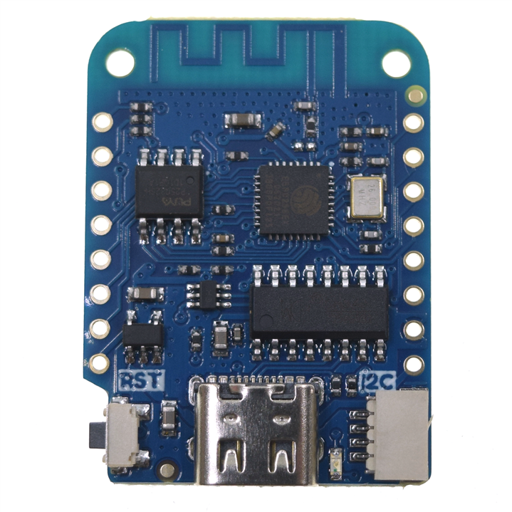
| Wemos D1 Mini |
Wemos D1 Mini is an ESP8266-based development board with built-in wifi. I used it here for sending sensor data to the cloud server through wifi.
|
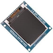
| TFT Display |
I used a 1.8 inch TFT display to display the information. This display communicates with the Wemos D1 Mini using the SPI bus. |
Making the Hardware
Some parts of the hardware preparation was shown in previous blogs. Here I will show the finalization of the main hardware unit. The following block diagram shows the interconnections and operation of the hardware unit.
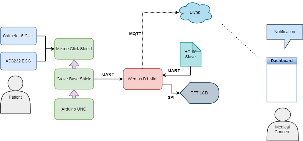
For a better understanding, we can discuss the hardware unit into two separate parts. One part is based on Arduino (left part). Another part is based on Wemos D1 Mini (right side). You may ask why I am using two microcontroller units here. I tried to complete it using Arduino only where I assumed I will use an ethernet shield for transmitting data to the cloud. But when writing the program I realized that for SPO2 calculation we need lots of data memory. I tried with the library from Sparkfun and found that for only SpO2 calculation this code required 90% of the dynamic memory.

With all the libraries included that are required for the compilation of the full sketch, the dynamic memory requirement exceeds 200 percent.
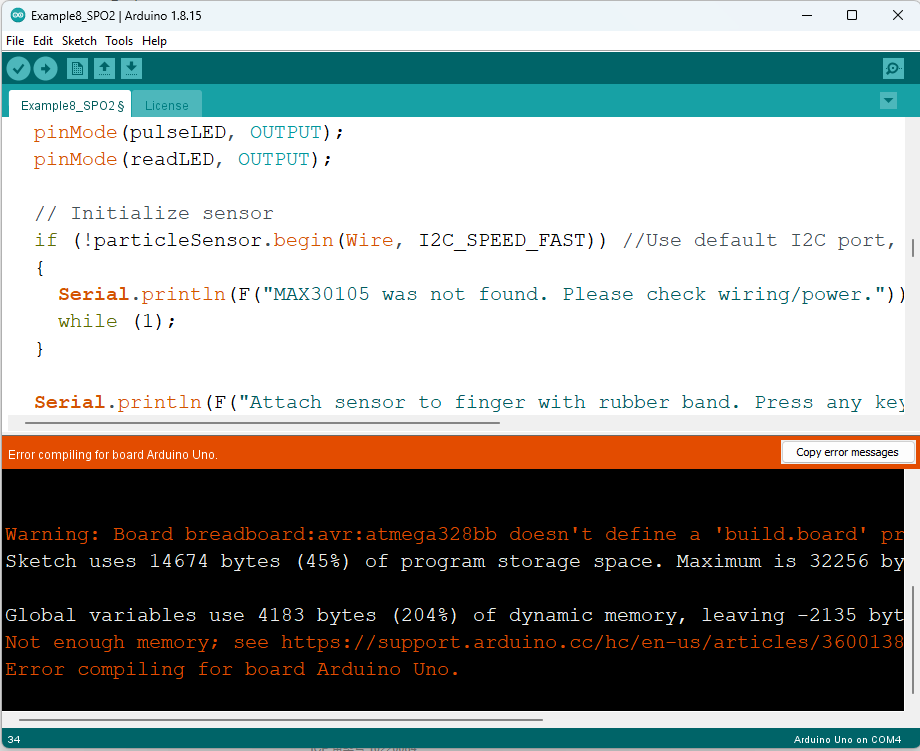
For this reason, I have decided to separate the tasks into two microcontroller units. I am using Arduino Uno only for interfacing the oximeter 5-click board and ECG sensor. After measuring the parameters it just sends the data through UART to the second unit that is based on Wemos D1 mini. The working algorithm for this part is illustrated by the following flowchart.

Sketch for Arduino
The Arduino sketch for the main unit is very simple. The work of this code is just collecting the sensor data and printing the data to the serial port. For oxygen and pulse calculation from the oximeter data, I used the DFRobot_MAX30102 library. The library is available on GitHub. You can download it from here. Another library that can be used for the same purpose is the Sparkfun MAX300105 library but this library needs more dynamic memory compared to the DF_Robot one. For this reason, I prefer the library from DF_Robot especially when you use a graphic display. Because graphics display also use lots of space in dynamic memory.
The full code for the Arduino part of the main unit is provided below.
/*
 * Md. Khairul Alam
 * Date: 16/11/2022
 */


#include <DFRobot_MAX30102.h>

DFRobot_MAX30102 particleSensor;

/*
Macro definition options in sensor configuration
sampleAverage: SAMPLEAVG_1 SAMPLEAVG_2 SAMPLEAVG_4
               SAMPLEAVG_8 SAMPLEAVG_16 SAMPLEAVG_32
ledMode:       MODE_REDONLY  MODE_RED_IR  MODE_MULTILED
sampleRate:    PULSEWIDTH_69 PULSEWIDTH_118 PULSEWIDTH_215 PULSEWIDTH_411
pulseWidth:    SAMPLERATE_50 SAMPLERATE_100 SAMPLERATE_200 SAMPLERATE_400
               SAMPLERATE_800 SAMPLERATE_1000 SAMPLERATE_1600 SAMPLERATE_3200
adcRange:      ADCRANGE_2048 ADCRANGE_4096 ADCRANGE_8192 ADCRANGE_16384
*/
void setup()
{
  //Init serial
  Serial.begin(115200);
  pinMode(5, INPUT); // Setup for leads off detection LO +
  pinMode(9, INPUT); // Setup for leads off detection LO -
  /*!
   *@brief Init sensor
   *@param pWire IIC bus pointer object and construction device, can both pass or not pass parameters (Wire in default)
   *@param i2cAddr Chip IIC address (0x57 in default)
   *@return true or false
   */
  while (!particleSensor.begin()) {
    //Serial.println("MAX30102 was not found");
    delay(1000);
  }

  /*!
   *@brief Use macro definition to configure sensor
   *@param ledBrightness LED brightness, default value: 0x1F(6.4mA), Range: 0~255(0=Off, 255=50mA)
   *@param sampleAverage Average multiple samples then draw once, reduce data throughput, default 4 samples average
   *@param ledMode LED mode, default to use red light and IR at the same time
   *@param sampleRate Sampling rate, default 400 samples every second
   *@param pulseWidth Pulse width: the longer the pulse width, the wider the detection range. Default to be Max range
   *@param adcRange ADC Measurement Range, default 4096 (nA), 15.63(pA) per LSB
   */
  particleSensor.sensorConfiguration(/*ledBrightness=*/50, /*sampleAverage=*/SAMPLEAVG_4, \
                        /*ledMode=*/MODE_MULTILED, /*sampleRate=*/SAMPLERATE_100, \
                        /*pulseWidth=*/PULSEWIDTH_411, /*adcRange=*/ADCRANGE_16384);
}

int32_t SPO2; //SPO2
int8_t SPO2Valid; //Flag to display if SPO2 calculation is valid
int32_t heartRate; //Heart-rate
int8_t heartRateValid; //Flag to display if heart-rate calculation is valid

void loop()
{
  //only read ecg when ecg lead placement is detected
  if((digitalRead(5) != 1)&&(digitalRead(9) != 1)){
    Serial.print("EC"); //key EC added for edge of seperation in receiver side
    Serial.println(analogRead(A1));
    delay(1);
  }

  else{
  //Serial.println(F("Wait about four seconds"));
  particleSensor.heartrateAndOxygenSaturation(/**SPO2=*/&SPO2, /**SPO2Valid=*/&SPO2Valid,
                          /**heartRate=*/&heartRate, /**heartRateValid=*/&heartRateValid);

  int ht = heartRate;
  int ht_valid = heartRateValid;
  int spo2 = SPO2;
  int spo2_valid = SPO2Valid;

  if(ht_valid){  //only sends when data is valid
    Serial.print("HR"); //added a key HR so that we can seperate it in receiver side
    Serial.println(ht);
  }

  if(spo2_valid){
    Serial.print("SP");
    Serial.println(spo2);
  }
 }

}
The physical things look as follows. The extended grove cable is for connecting the second unit through UART.
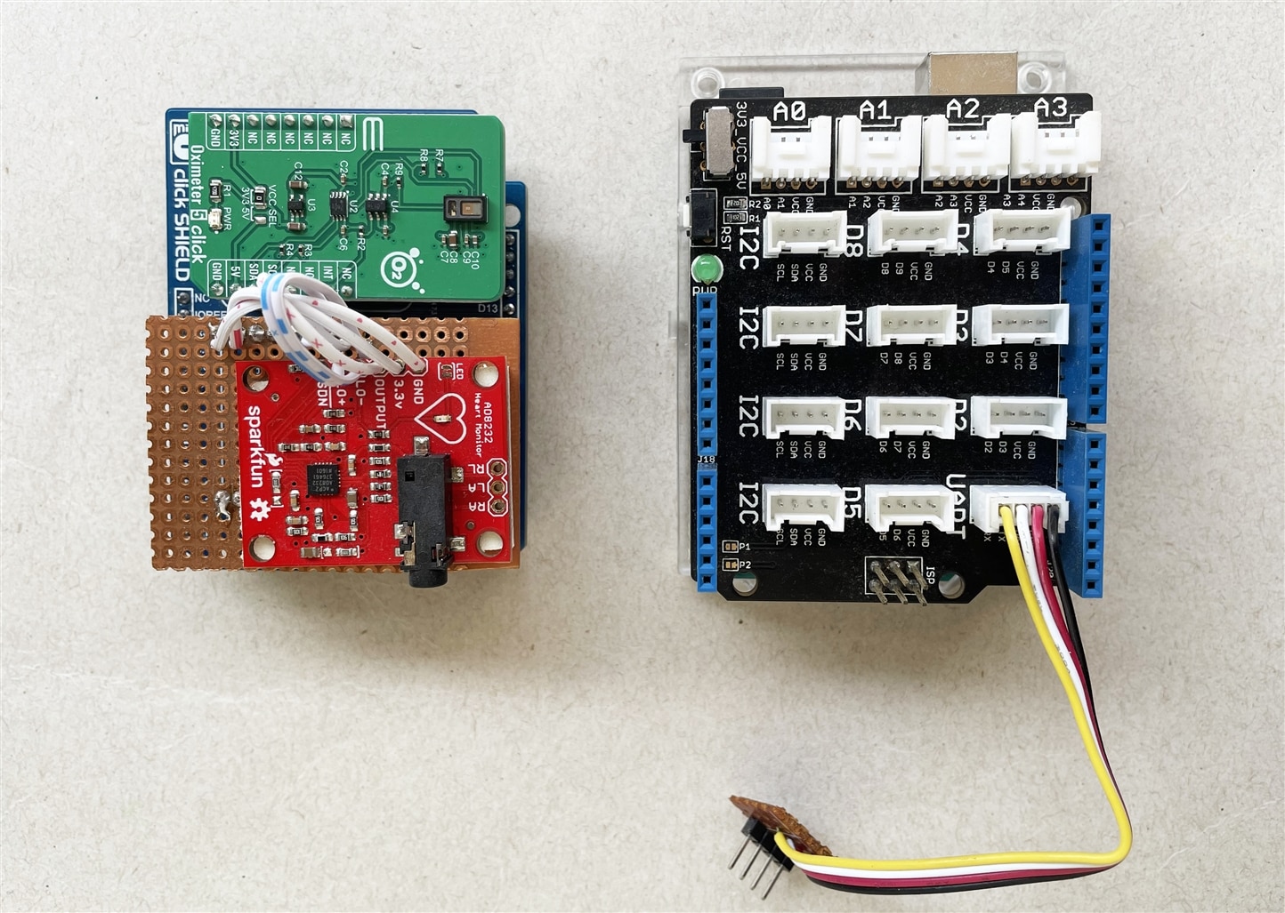
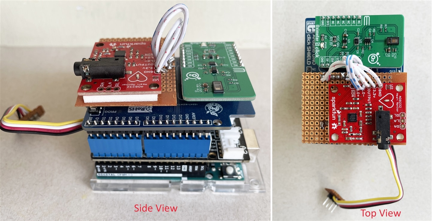
After attaching the sensor unit and the Arduino board with the Grove shield the hardware looks like the following photo. This part does not contain any display. So data visualization is not possible but we will visualize this data from the second unit that contains a TFT display and receive data from this part through UART.
Hardware (2nd Part)
This unit receives the sensor data from other units. It collects the data from the wearable unit using Bluetooth and from the main sensor unit through UART. After getting the data it performs simple processing. After that, it displays the data to the graphics TFT display and uploads the data to the cloud server. Cloud server stores the data as well as visualizes the data in a graphical dashboard. Health concerns and doctors can observe the data and can perform further analysis if required.
For uploading the data to the cloud we need any sort of internet connection. WiFi is a good option that provides a portable solution and is cost-effective. Lots of low-cost WiFi module is available that can be programmed with Arduino. I am going to use one of the most popular and maker-friendly WiFi chips named ESP8266. Based on this chip hundreds of development boards were made. Wemos D1 Mini is one of them with a small form factor and includes a built-in programmer.
The schematic for the second unit is as follows.
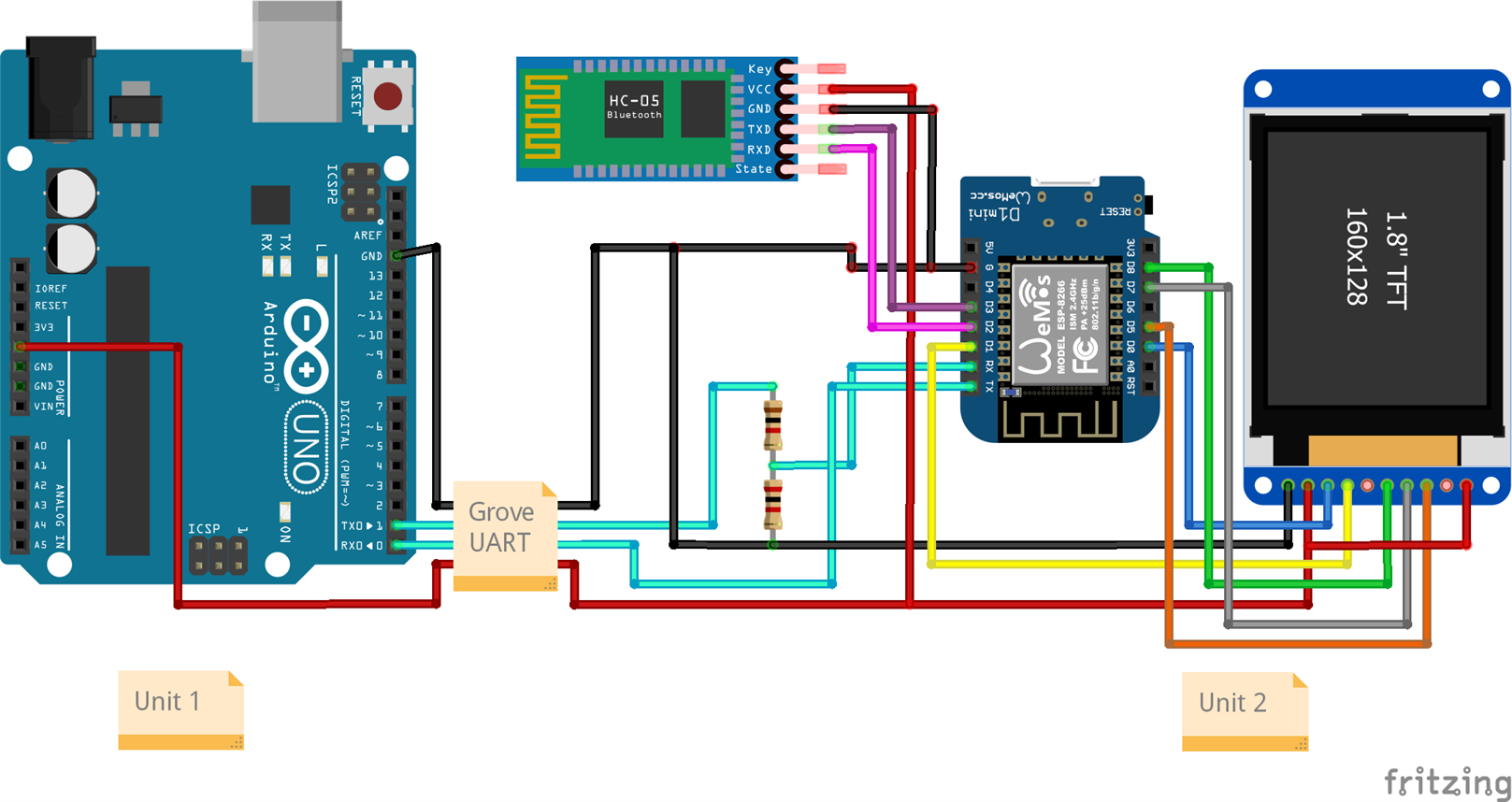
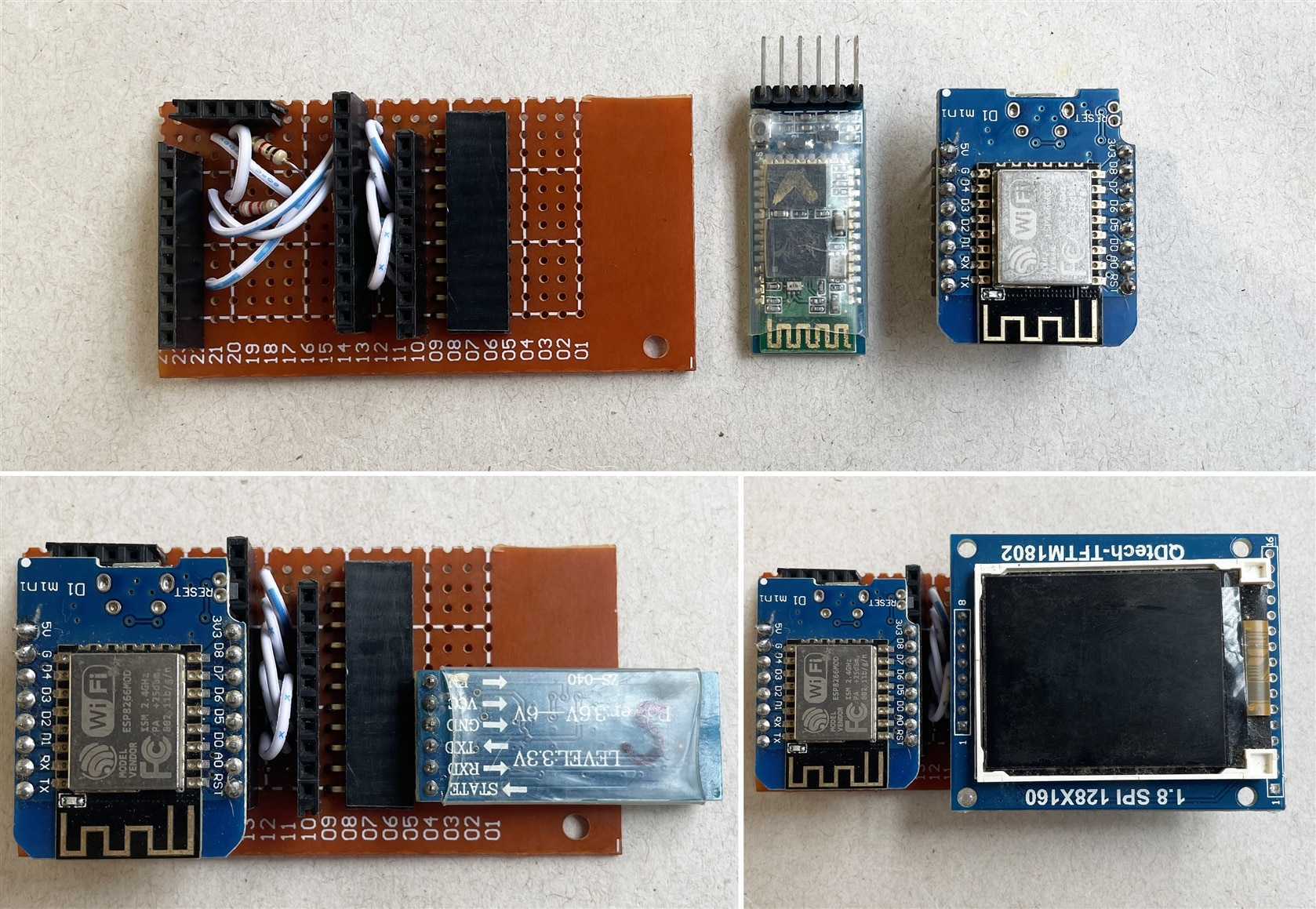
Two units are connected through Grove UART cable. As Wemos D1 mini operates at 3.3V, so I converted the output voltage from the Arduin TX pin by a resistors voltage divider to make it compatible with the Wemos board. The hardware unit looks like below:
Sketch for Wemos D1 Mini
The job of the firmware program of Wemos D1 Mini is to gather the data from the wearable unit and from the main unit, display the data to the TFT and upload the data to the cloud. The algorithm of the firmware is illustrated by the following flowchart.
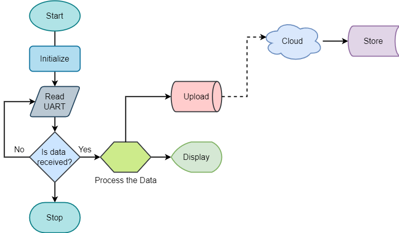
The firmware code for Wemos D1 Mini is attached below. For the successful compilation of the sketch, you will require QDTech_8266 TFT library with the Adafruit_GFX library. You can download the library from the GitHub repository. The library is here. Two UART port is required for the operation. Wemos has one hardware serial. So another software serial is implemented using the Arduino SoftSerial library. Bluetooth module is connected through the software serial that receives data from the wearable unit. For the Blynk cloud connection, you need to add blynk library from here.
#define TFT_CS  15  // Chip select line for TFT display
#define TFT_DC   5  // Data/command line for TFT
#define TFT_RST  16  // Reset line for TFT (or connect to +5V)
#define BUFFPIXEL 20

#include <Adafruit_GFX.h>    // Core graphics library
#include <QDTech_8266.h> // Hardware-specific library
#include <SPI.h>
#include <SoftwareSerial.h>

#include <ESP8266WiFi.h>
#include <BlynkSimpleEsp8266.h>

const byte rxPin = 3;
const byte txPin = 2;

// Set up a new SoftwareSerial object
SoftwareSerial bluetoothSerial (rxPin, txPin);

/* Comment this out to disable prints and save space */
#define BLYNK_PRINT Serial

//use the hardware SPI pins
Adafruit_ST7735 tft = Adafruit_ST7735(TFT_CS, TFT_DC, TFT_RST);

  int color1 = 100, color3 = 336, color2 = 7500;
  int x = 3;
  int width = 122;
  int height = 35;
  int roundness = 2;

/**********variables for color***********************/
int BLACK = 100;
int BLUE = 200;
int WHITE = 0;
int RED = 336;
int GREEN = 264;

int spo2_value = 0;
int pulse_rate = 0;
float deep_sleep = 0;
float light_sleep = 0;
int step_count = 0;
int ecg_data = 0;

String inputString = "";         // a string to hold incoming data
boolean stringComplete = false;  // whether the string is complete
String inputString1 = "";         // a string to hold incoming data
boolean stringComplete1 = false;  // whether the string is complete

// You should get Auth Token in the Blynk App.
// Go to the Project Settings (nut icon).
char auth[] = "YourAuthToken";

// Your WiFi credentials.
// Set password to "" for open networks.
char ssid[] = "YourNetworkName";
char pass[] = "YourPassword";

void setup(void) {
  Serial.begin(115200);
  bluetoothSerial.begin(9600);

  inputString.reserve(50);
  inputString1.reserve(50);

  SPI.setClockDivider(SPI_CLOCK_DIV2);
  tft.init();

  tft.fillScreen(WHITE);
  delay(1000);

  updateHomeScreen();
  tft.setRotation( 0 );
  tft.setCursor(5, 24);
  tft.setTextColor(WHITE);
  tft.setTextSize(2);
  tft.println("SpO2:");
  tft.setCursor(75, 10);
  tft.setTextColor(BLUE);
  tft.setTextSize(4);
  tft.println("--");

  tft.setCursor(5, 63);
  tft.setTextColor(WHITE);
  tft.setTextSize(2);
  tft.println("BPM:");
  tft.setCursor(75, 51);
  tft.setTextColor(BLUE);
  tft.setTextSize(4);
  tft.println("--");

  tft.setCursor(5, 95);
  tft.setTextColor(WHITE);
  tft.setTextSize(1);
  tft.println("Steps:");
  tft.setCursor(75, 88);
  tft.setTextColor(BLUE);
  tft.setTextSize(2);
  tft.println("--");

  tft.setCursor(5, 113);
  tft.setTextColor(WHITE);
  tft.setTextSize(1);
  tft.println("Distance:");
  tft.setCursor(75, 105);
  tft.setTextColor(BLUE);
  tft.setTextSize(2);
  tft.println("--");

  tft.setCursor(5, 130);
  tft.setTextColor(WHITE);
  tft.setTextSize(1);
  tft.println("D Sleep:");
  tft.setCursor(75, 123);
  tft.setTextColor(BLUE);
  tft.setTextSize(2);
  tft.println("--");

  tft.setCursor(5, 147);
  tft.setTextColor(WHITE);
  tft.setTextSize(1);
  tft.println("L Sleep:");
  tft.setCursor(75, 141);
  tft.setTextColor(BLUE);
  tft.setTextSize(2);
  tft.println("--");

  Blynk.begin(auth, ssid, pass);
  delay(2000);
}


void loop (){

  serialEvent();
  softSerialEvent();
  if(stringComplete){
    String key = inputString.substring(0, 2);
    String received_value = inputString.substring(2);

    if(key == "SP") {
      spo2_value = received_value.toInt();
      Blynk.virtualWrite(V1, spo2_value);
    }
    else if(key == "HR") {
      pulse_rate = received_value.toInt();
      Blynk.virtualWrite(V2, pulse_rate);
    }
    else if(key == "EC") {
      ecg_data = received_value.toInt();
      Blynk.virtualWrite(V3, ecg_data);
    }

    update_spo2_bpm(spo2_value, pulse_rate);


    inputString = "";
    stringComplete = false;
    }
  if (stringComplete1) {
    int firstCommaIndex = inputString1.indexOf(',');
    int secondCommaIndex = inputString1.indexOf(',', firstCommaIndex+1);

    String firstValue = inputString1.substring(0, firstCommaIndex);
    String secondValue = inputString1.substring(firstCommaIndex+1, secondCommaIndex);
    String thirdValue = inputString1.substring(secondCommaIndex+1);

    int step_count = firstValue.toInt();
    int deep_sleep = secondValue.toInt();
    int light_sleep = thirdValue.toInt();
    update_activity(step_count, deep_sleep, light_sleep);

    Blynk.virtualWrite(V4, step_count);
    Blynk.virtualWrite(V5, deep_sleep);
    Blynk.virtualWrite(V6, light_sleep);

    Serial.println(step_count);
    Serial.println(deep_sleep);
    Serial.println(light_sleep);

    inputString1 = "";
    stringComplete1 = false;
  }
  delay(1);
  Blynk.run();

}


void updateHomeScreen(){
  tft.drawRoundRect(x, 4, width, height*2, roundness, color1);
  tft.fillRoundRect(x, 4, width, height*2, roundness, color1);
  tft.drawRoundRect(x, 79, width, height, roundness, color2);
  tft.fillRoundRect(x, 79, width, height, roundness, color2);
  tft.drawRoundRect(x, 119, width, height+1, roundness, color3);
  tft.fillRoundRect(x, 119, width, height+1, roundness, color3);
}

void serialEvent() {
  while (Serial.available()) {
    // get the new byte:
    char inChar = (char)Serial.read();
    // if the incoming character is a newline, set a flag
    // so the main loop can do something about it:
    if (inChar == '\n') {
      stringComplete = true;
    }
    else
    // add it to the inputString:
      inputString += inChar;
  }
}

void softSerialEvent() {
  while (bluetoothSerial.available()) {
    // get the new byte:
    char inChar = (char)bluetoothSerial.read();
    // if the incoming character is a newline, set a flag
    // so the main loop can do something about it:
    if (inChar == '\n') {
      stringComplete1 = true;
    }
    else
    // add it to the inputString:
      inputString1 += inChar;
  }
}

void update_spo2_bpm(int spo2, int bpm){
  tft.setCursor(5, 24);
  tft.setTextColor(WHITE);
  tft.setTextSize(2);
  tft.println("SpO2:");

  tft.setRotation(2);
  tft.drawRoundRect(x, 119, width/2, height+1, roundness, color3);
  tft.fillRoundRect(x, 119, width/2, height+1, roundness, color3);
  tft.setRotation(0);

  tft.setCursor(75, 10);
  tft.setTextColor(BLUE);
  tft.setTextSize(4);
  if(spo2>0)
    tft.println(spo2);
  else
    tft.println("--");

  tft.setCursor(5, 63);
  tft.setTextColor(WHITE);
  tft.setTextSize(2);
  tft.println("BPM:");


  tft.setRotation(2);
  tft.drawRoundRect(x, 79, width/2, height, roundness, color2);
  tft.fillRoundRect(x, 79, width/2, height, roundness, color2);
  tft.setRotation(0);

  tft.setCursor(75, 51);
  tft.setTextColor(BLUE);
  tft.setTextSize(4);
  if(bpm>0)
    tft.println(bpm);
  else
    tft.println("--");

  delay(5);
 }

void update_activity(int step_count, int deep_sleep, int light_sleep){
  tft.setRotation(2);
  tft.drawRoundRect(x, 4, width, height*2, roundness, color1);
  tft.fillRoundRect(x, 4, width, height*2, roundness, color1);
  tft.setRotation(0);

  tft.setCursor(5, 95);
  tft.setTextColor(WHITE);
  tft.setTextSize(1);
  tft.println("Steps:");
  tft.setCursor(75, 88);
  tft.setTextColor(BLUE);
  tft.setTextSize(2);

  tft.println(step_count);

  tft.setCursor(5, 113);
  tft.setTextColor(WHITE);
  tft.setTextSize(1);
  tft.println("Distance:");
  tft.setCursor(75, 105);
  tft.setTextColor(BLUE);
  tft.setTextSize(2);
  tft.println(int(step_count*0.3));

  tft.setCursor(5, 130);
  tft.setTextColor(WHITE);
  tft.setTextSize(1);
  tft.println("D Sleep:");
  tft.setCursor(75, 123);
  tft.setTextColor(BLUE);
  tft.setTextSize(2);
  tft.println(deep_sleep);

  tft.setCursor(5, 147);
  tft.setTextColor(WHITE);
  tft.setTextSize(1);
  tft.println("L Sleep:");
  tft.setCursor(75, 141);
  tft.setTextColor(BLUE);
  tft.setTextSize(2);
  tft.println(light_sleep);
}
Demo Video
A demonstration of my project is shown in the following video.
Conclusion
I believe the complete system could be more lucrative with a 3D-printed case. Several more options can be added. The PCB can be custom printed. But due to time limitations, I can not complete all those tasks. Though I received the hardware late I tried my best to make it workable and feature-rich. In the future, I wish to update the system with more functions and good outlooking.
Thank you very much for reading my blogs with patience.
*******************************************************************************************************************************************************
Previous Blogs
- Blog #5 - Activity & Sleep Tracking Unit
- Blog #4 - Experimenting with LSM6DSL Click
- Blog #3 - Experimenting with ECG Sensor
- Blog #2 - Experimenting with Oximeter 5 Click
- Blog #1 - Introduction
Summary
This was a very nice competition. I gave lots of effort and time into it and learned a lot. I have experimented with several sensors and software libraries during my work. I have received lots of inspiring comments, suggestions, and messages. Inspiring comments and feedback always inspire and motivates. Thanks to my readers, thanks to the Element14 community, and finally special thanks to MikroElektronika for sponsoring me.
*************Thank you***************

