element14 Community
element14 Community
    Register Log In
  • Site
  • Search
  • Log In Register
  • About Us
  • Community Hub
    Community Hub
    • What's New on element14
    • Feedback and Support
    • Benefits of Membership
    • Personal Blogs
    • Members Area
    • Achievement Levels
  • Learn
    Learn
    • Ask an Expert
    • eBooks
    • element14 presents
    • Learning Center
    • Tech Spotlight
    • STEM Academy
    • Webinars, Training and Events
    • Learning Groups
  • Technologies
    Technologies
    • 3D Printing
    • FPGA
    • Industrial Automation
    • Internet of Things
    • Power & Energy
    • Sensors
    • Technology Groups
  • Challenges & Projects
    Challenges & Projects
    • Design Challenges
    • element14 presents Projects
    • Project14
    • Arduino Projects
    • Raspberry Pi Projects
    • Project Groups
  • Products
    Products
    • Arduino
    • Avnet Boards Community
    • Dev Tools
    • Manufacturers
    • Multicomp Pro
    • Product Groups
    • Raspberry Pi
    • RoadTests & Reviews
  • Store
    Store
    • Visit Your Store
    • Choose another store...
      • Europe
      •  Austria (German)
      •  Belgium (Dutch, French)
      •  Bulgaria (Bulgarian)
      •  Czech Republic (Czech)
      •  Denmark (Danish)
      •  Estonia (Estonian)
      •  Finland (Finnish)
      •  France (French)
      •  Germany (German)
      •  Hungary (Hungarian)
      •  Ireland
      •  Israel
      •  Italy (Italian)
      •  Latvia (Latvian)
      •  
      •  Lithuania (Lithuanian)
      •  Netherlands (Dutch)
      •  Norway (Norwegian)
      •  Poland (Polish)
      •  Portugal (Portuguese)
      •  Romania (Romanian)
      •  Russia (Russian)
      •  Slovakia (Slovak)
      •  Slovenia (Slovenian)
      •  Spain (Spanish)
      •  Sweden (Swedish)
      •  Switzerland(German, French)
      •  Turkey (Turkish)
      •  United Kingdom
      • Asia Pacific
      •  Australia
      •  China
      •  Hong Kong
      •  India
      •  Korea (Korean)
      •  Malaysia
      •  New Zealand
      •  Philippines
      •  Singapore
      •  Taiwan
      •  Thailand (Thai)
      • Americas
      •  Brazil (Portuguese)
      •  Canada
      •  Mexico (Spanish)
      •  United States
      Can't find the country/region you're looking for? Visit our export site or find a local distributor.
  • Translate
  • Profile
  • Settings
Sustain The World - Design Challenge
  • Challenges & Projects
  • Design Challenges
  • Sustain The World - Design Challenge
  • More
  • Cancel
Sustain The World - Design Challenge
Blog Garbage Collector #7 Clamp and Base
  • Blog
  • Forum
  • Documents
  • Polls
  • Files
  • Events
  • Mentions
  • Sub-Groups
  • Tags
  • More
  • Cancel
  • New
  • Share
  • More
  • Cancel
Group Actions
  • Group RSS
  • More
  • Cancel
Engagement
  • Author Author: wanfp97
  • Date Created: 23 Sep 2020 5:21 PM Date Created
  • Views 1354 views
  • Likes 6 likes
  • Comments 6 comments
  • infineon
  • xmc4700
  • garbage collector
  • servo
  • tle94112
  • sustain the world
Related
Recommended

Garbage Collector #7 Clamp and Base

wanfp97
wanfp97
23 Sep 2020

Blog List:

Garbage Collector #1 Introduction

Garbage Collector #2 Clamp testing

Garbage Collector #3 Seeking help from Infineon's Technical Supports

Garbage Collector #4 Some basic interactions with the shields

Garbage Collector #5 Base testing

Garbage Collector #6 Wireless Controller

Garbage Collector #7 Clamp and Base

Garbage Collector #8 Clamp Improvement

Garbage Collector #9 Doubling the maximum current

Garbage Collector #10 Summary


Hello guys, in this blog I will write about putting the base and clamp together and control them wirelessly.


In my previous blog, I have successfully control the base as well as clamp separately. However, when I put them all together, I have noticed that I will need too much of Interrupt pins ( an interrupt pin for each particular action ). Therefore, I have decided to do some improvement on my coding so that I can use fewer interrupt pins.

Since the "forward", "backward", "left", and "right" instructions are mutually exclusive, the solution that I can think of is that instead of using separate interrupt pins for "forward", "backward", "left", and "right", I will be sending a bus data from NodeMCU to the XMC4700 telling it that which direction should it go, then I can only use 1 interrupt for all of them.

For Example:

DIRECTION_Bus_IO [1:0]Direction
00Forward
01Backward
10Left
11Right


Similarly:

CLAMP_Bus_IO [1:0]Actions
00clamp up
01clamp down
10clamp open
11clamp close


The table below compares the pin count for the previous case and the new case:

Previous InterruptPrevious GPIONew InterruptNew GPIO
FORWARDDIRECTIONDIRECTION_Bus_IO [0]
FORWARDCLAMPDIRECTION_Bus_IO [1]
LEFTCLAMP_Bus_IO [0]
RIGHTCLAMP_Bus_IO [1]
CLAMP UP
CLAMP DOWN
CLAMP OPEN
CLAMP CLOSE
Total8024
Previous Case Total pins8New Case Total pins6


Using the new method not only reduces the interrupts pins but also decreases the total pins needed. The only thing I will have to sacrifice is that I can't give the instructions that use the same interrupt at the same time. Since I know that they are all mutually exclusive, that will do no harm to me and I'm literally sacrificing nothing and reduced the interrupt pin count as well as the total pin count.


As for the coding part, I have added 2 new FreeRTOS task to check the respective BUS_IO and call out the intended task:

void DIRECTION_Task(void *p){


while(1){


if (xSemaphoreTake(DIRECTION_interruptSemaphore, portMAX_DELAY) == pdPASS){


direction_status = BUS_IO_Read(&DIRECTION_BUS_IO);


switch(direction_status){


case 0:
xSemaphoreGiveFromISR(FORWARD_interruptSemaphore, NULL);
break;


case 1:
xSemaphoreGiveFromISR(BACKWARD_interruptSemaphore, NULL);
break;


case 2:
xSemaphoreGiveFromISR(LEFT_interruptSemaphore, NULL);
break;


case 3:
xSemaphoreGiveFromISR(RIGHT_interruptSemaphore, NULL);
break;


}
}
}
}


void CLAMP_Task(void *p){


while(1){


if (xSemaphoreTake(CLAMP_interruptSemaphore, portMAX_DELAY) == pdPASS){


clamp_status = BUS_IO_Read(&CLAMP_BUS_IO);


switch(clamp_status){


case 0:
xSemaphoreGiveFromISR(UP_interruptSemaphore, NULL);
break;


case 1:
xSemaphoreGiveFromISR(DOWN_interruptSemaphore, NULL);
break;


case 2:
xSemaphoreGiveFromISR(OPEN_interruptSemaphore, NULL);
break;


case 3:
xSemaphoreGiveFromISR(CLOSE_interruptSemaphore, NULL);
break;


}
}
}
}


Under normal circumstances, the CLAMP_Task and DIRECTION_Task will not run since the respective semaphore are not available. When Interrupt occurs, the IRQ_Handler will give the respective semaphore so that the DIRECTION_Task or the CLAMP_task can in return give semaphore for the respective task based on the inputs in the BUS_IO.

Below are the codes for the IRQ_Handler:

void DIRECTION_IRQHandler(void){


xSemaphoreGiveFromISR(DIRECTION_interruptSemaphore, NULL);
}


void CLAMP_IRQHandler(void){


xSemaphoreGiveFromISR(CLAMP_interruptSemaphore, NULL);
}


The project file can be cloned through the following Github link:

https://github.com/wanfp97/GarbageCollector


I have also uploaded the updated version of the Controller.ino file on the Github so that you guys can upload it to the NodeMCU.


The mobile application used to control the Garbage Collector has not been changed so the mobile application in the previous blog post can be used.


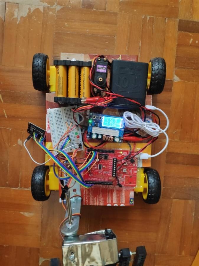
Putting the base and the clamp together:

image


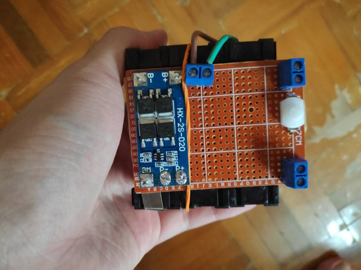
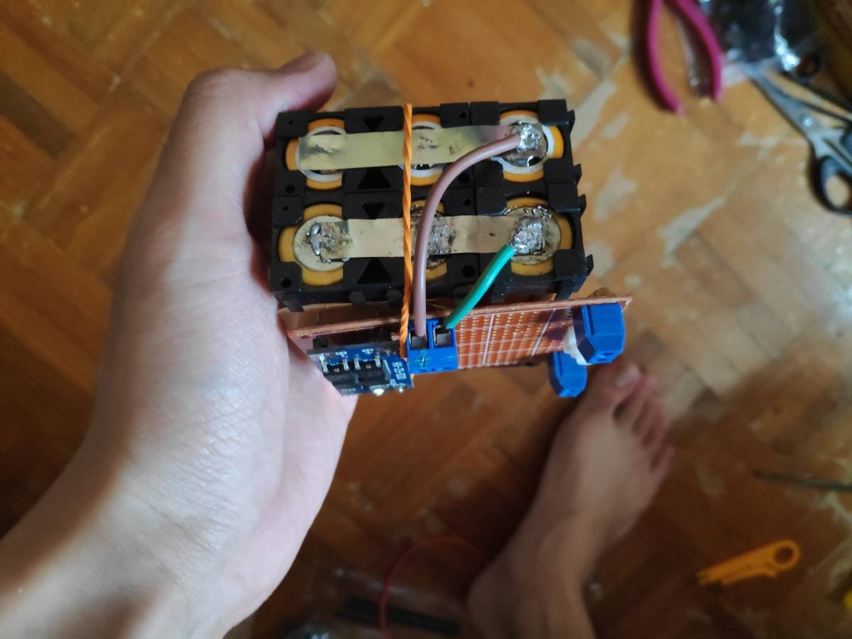
Adding BMS module for balanced charging and discharge purpose:

I have soldered HX-2S-D20 BMS module and a switch to control the charging and discharging of the batteries.

image


image

I have uploaded everything to their respective Kit and below is the test

You don't have permission to edit metadata of this video.
Edit media
x
image
Upload Preview
image

The Clamp is still not strong enough and there is some jitter on the servo. Hopefully, I can find a solution for these and update it in my next blog.

That's all for this blog, see you next blog.

  • Sign in to reply

Top Comments

  • DAB
    DAB over 4 years ago +1
    Nice try, but your whole set up will only work for light weight objects. DAB
  • jw0752
    jw0752 over 4 years ago +1
    Hi, I really like what you have done and it is in good scientific protocol to show the weakness as well as the strength. If there is any chance that the force that opens the clamp has enough strength you…
  • dubbie
    dubbie over 4 years ago +1
    An interesting little mobile robot is beginning to emerge. There are several methods for increasing the force of the closing grippers, such as a screw thread between the jaws, scissors can work if the…
  • wanfp97
    wanfp97 over 4 years ago in reply to dubbie

    Hi Dubbie,


    Thanks for your suggestions.


    Fook Peng

    • Cancel
    • Vote Up +1 Vote Down
    • Sign in to reply
    • More
    • Cancel
  • wanfp97
    wanfp97 over 4 years ago in reply to jw0752

    Hi John,


    Thanks for the suggestions. I will definitely try them out.


    Fook Peng

    • Cancel
    • Vote Up 0 Vote Down
    • Sign in to reply
    • More
    • Cancel
  • wanfp97
    wanfp97 over 4 years ago in reply to DAB

    Hi DAB,


    Thanks for pointing that out, I will try to improve it in future blog post.


    Fook Peng

    • Cancel
    • Vote Up 0 Vote Down
    • Sign in to reply
    • More
    • Cancel
  • dubbie
    dubbie over 4 years ago

    An interesting little mobile robot is beginning to emerge. There are several methods for increasing the force of the closing grippers, such as a screw thread between the jaws, scissors can work if the pivot point is placed correctly, plus adding rubber or other non slip surfaces to the jaws also helps.


    You can reduce the gripper jittering about by slowing down the speed at which it moves by inserting one ofr more way-points with small delays between them.


    You could try an alternative approach of using two counter-rotating brushes to sweep up the objects, much the same as road sweepers. You would then have the problem of getting the dirt into the bin somehow, but the sweeping approach does work quite well.


    Dubbie

    • Cancel
    • Vote Up +1 Vote Down
    • Sign in to reply
    • More
    • Cancel
  • jw0752
    jw0752 over 4 years ago

    Hi,


    I really like what you have done and it is in good scientific protocol to show the weakness as well as the strength. If there is any chance that the force that opens the clamp has enough strength you could add a little counter tension with a spring or small rubber band. Then when the clamp closes it will have that additional force to help it grab on. Also you could add some rubber surface tape to the clamps to give them additional friction. Great project.


    John

    • Cancel
    • Vote Up +1 Vote Down
    • Sign in to reply
    • More
    • Cancel
>
element14 Community

element14 is the first online community specifically for engineers. Connect with your peers and get expert answers to your questions.

  • Members
  • Learn
  • Technologies
  • Challenges & Projects
  • Products
  • Store
  • About Us
  • Feedback & Support
  • FAQs
  • Terms of Use
  • Privacy Policy
  • Legal and Copyright Notices
  • Sitemap
  • Cookies

An Avnet Company © 2025 Premier Farnell Limited. All Rights Reserved.

Premier Farnell Ltd, registered in England and Wales (no 00876412), registered office: Farnell House, Forge Lane, Leeds LS12 2NE.

ICP 备案号 10220084.

Follow element14

  • X
  • Facebook
  • linkedin
  • YouTube