


Change Never Changes
I have lots of ideas, but I need to get this project moving along, so I have started down the final path, but started more fresh than before. I have decided to use the other Edison and the mini-board since I am putting all of this in a 1U enclosure. Here are my hardware plans going down the stretch.
Outlet Switching
I am going to use an eight port version of the relay module posted right below. I have the module, but it is wired up currently for testing as I have just finished testing my circuit I am going to build to control this set of relays.
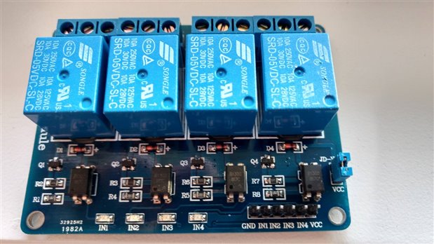
Now with these Opto-isolated relay modules, the pins need to be floating or tied to 5V to be off and connected to ground to be in a on state. For this I have wired up a simple inverter circuit that helps me with another problem with the mini and that is 1.8V.
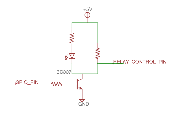
This is one of eight I will use to control the 8 relays on the board for the 8 outlets. The LEDs will go the front of the unit it display power status to each outlet. I plan on making this control board to plug into the relay circuit to keep the wire count to a minimal.
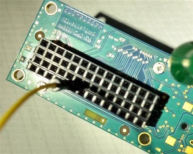
Edison Mini-board
I have added a header to the bottom of the Mini-board and that will plug into another board for power and GPIO. That other board will be mounted inside the PDU, so that the Edison is easily removed if need be.
Only other thing I need to control is the LCD that will be mounted in the PDU. I will use the Adafruit 4-Bit Level Converter for to bring the I2C 1.8V to 5V fro the LCD.

Top Comments
-

gpolder
-
Cancel
-
Vote Up
+3
Vote Down
-
-
Sign in to reply
-
More
-
Cancel
Comment-

gpolder
-
Cancel
-
Vote Up
+3
Vote Down
-
-
Sign in to reply
-
More
-
Cancel
Children