element14 Community
element14 Community
    Register Log In
  • Site
  • Search
  • Log In Register
  • About Us
  • Community Hub
    Community Hub
    • What's New on element14
    • Feedback and Support
    • Benefits of Membership
    • Personal Blogs
    • Members Area
    • Achievement Levels
  • Learn
    Learn
    • Ask an Expert
    • eBooks
    • element14 presents
    • Learning Center
    • Tech Spotlight
    • STEM Academy
    • Webinars, Training and Events
    • Learning Groups
  • Technologies
    Technologies
    • 3D Printing
    • FPGA
    • Industrial Automation
    • Internet of Things
    • Power & Energy
    • Sensors
    • Technology Groups
  • Challenges & Projects
    Challenges & Projects
    • Design Challenges
    • element14 presents Projects
    • Project14
    • Arduino Projects
    • Raspberry Pi Projects
    • Project Groups
  • Products
    Products
    • Arduino
    • Avnet Boards Community
    • Dev Tools
    • Manufacturers
    • Multicomp Pro
    • Product Groups
    • Raspberry Pi
    • RoadTests & Reviews
  • Store
    Store
    • Visit Your Store
    • Choose another store...
      • Europe
      •  Austria (German)
      •  Belgium (Dutch, French)
      •  Bulgaria (Bulgarian)
      •  Czech Republic (Czech)
      •  Denmark (Danish)
      •  Estonia (Estonian)
      •  Finland (Finnish)
      •  France (French)
      •  Germany (German)
      •  Hungary (Hungarian)
      •  Ireland
      •  Israel
      •  Italy (Italian)
      •  Latvia (Latvian)
      •  
      •  Lithuania (Lithuanian)
      •  Netherlands (Dutch)
      •  Norway (Norwegian)
      •  Poland (Polish)
      •  Portugal (Portuguese)
      •  Romania (Romanian)
      •  Russia (Russian)
      •  Slovakia (Slovak)
      •  Slovenia (Slovenian)
      •  Spain (Spanish)
      •  Sweden (Swedish)
      •  Switzerland(German, French)
      •  Turkey (Turkish)
      •  United Kingdom
      • Asia Pacific
      •  Australia
      •  China
      •  Hong Kong
      •  India
      •  Korea (Korean)
      •  Malaysia
      •  New Zealand
      •  Philippines
      •  Singapore
      •  Taiwan
      •  Thailand (Thai)
      • Americas
      •  Brazil (Portuguese)
      •  Canada
      •  Mexico (Spanish)
      •  United States
      Can't find the country/region you're looking for? Visit our export site or find a local distributor.
  • Translate
  • Profile
  • Settings
Vertical Farming
  • Challenges & Projects
  • Design Challenges
  • Vertical Farming
  • More
  • Cancel
Vertical Farming
Forum Mechanical Design Assistance???
  • Blog
  • Forum
  • Documents
  • Polls
  • Files
  • Events
  • Mentions
  • Sub-Groups
  • Tags
  • More
  • Cancel
  • New
Actions
  • Share
  • More
  • Cancel
Forum Thread Details
  • Replies 44 replies
  • Subscribers 9 subscribers
  • Views 5139 views
  • Users 0 members are here
  • vertical_farming
Related

Mechanical Design Assistance???

RWReynolds
RWReynolds over 10 years ago

Hey everyone,


I'm not a mechanical engineer by any stretch on anyone's imagination. I have one mechanical design issue that I'm not sure how to approach. I kind of know the theory, but I have no idea how to approach it practically.


Here's the problem...


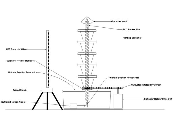
I have a load, my cultivator unit, that will be about 3' - 4' tall, maybe 12" to 18" in diameter and weigh between 20 and 40 lbs. The whole thing will be mounted on a lazy susan style turntable. The plan is to have a gear or pulley at the bottom that will be used with a hight torque stepper motor, and chain or belt, to rotate the cultivator. I'm using a stepper motor because they are pretty efficient and can be controlled very easily at very slow speeds. I want the rotation speed to be maybe 3 to 4 revolutions per day. A stepper would work well for this I think.


I have no idea how to properly size the motor. I see them speced at anywhere from 10s of oz-in to 1000s of oz-inches of torque. I get the concept of torque being rotational force. And that required torque has to do with acceleration time up to the desired RPM. But I have no idea how to relate this to my requirements.


I'm a 'puter software with some dangerous electronics knowledge guy! HELP!!! And feel free to tell me this just a stupid idea and I should be using a washing machine motor or something if that's the case.


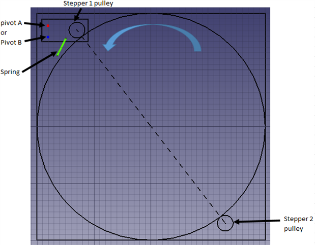
For reference, here's a drawing of the rig. Note the drive at the bottom right. Please excuse the misspelled labeling. I haven't gotten around to correcting it yet. lol...


image

  • Sign in to reply
  • Cancel

Top Replies

  • mcb1
    mcb1 over 10 years ago in reply to RWReynolds +2
    RWReynolds It looks like your design is coming together. Two comments. The stepper I linked to, Terry made this comment. This means your pulse number might be lower. (half) With the geared output you already…
  • Former Member
    Former Member over 9 years ago in reply to jw0752 +2
    Well, I received my 390mm dia lazy-susan a while back (image attached) but it'll sit in a corner some more yet. Reading lots that I hadn't been aware of e.g "inertia-matching" it seems direct-coupling…
  • clem57
    clem57 over 10 years ago +1
    Same here RWReynolds , but try this calculator for gear reduction to decrease speed Mechanical Gear Reduction Calculator C Edit: How about placing LED's around and turning on/off the set you want? Just…
Parents
  • saturnv
    saturnv over 10 years ago

    Rick, the relationship for rotations, or revolutions is gear ratio. For example, if you want 4 rotations of your cultivator per day that means you want ONE rotation every SIX hours, 1/2 rotation every 3 hours or 1/4 rotation every 1.5 hours. Normally you would want a gear ratio between your cultivator base size and your motors pulley size. However, since you're going to use stepper motors,  all you should need to do software-wise is make use of timing parameters to step the turntable once every 6 hours. Using wait, if/the, for, or pause commands or some other variable to reference the passing of time should work for you. For example is you want it to turn 1/4 turn, have it 'sleep for 5400 seconds (3600 secs/hr * 1.5 hrs=5400 seconds). Do that 16 times via an "if' or "while' type statements and your turntable will rotate 4 times in a 24 hour period. It's all about the math!

    • Cancel
    • Vote Up +1 Vote Down
    • Sign in to reply
    • Cancel
  • RWReynolds
    RWReynolds over 10 years ago in reply to saturnv

    Thanks for the info Michael...


    I think I have it worked out now. The control application will just be a simple state machine based on "the big loop". Reading sensors, performing control functions and logging them, via the radio, back to the central control/monitor system. I think control functions and reading the sensors should be very lightweight. There's no sensor that needs to be read more than once a second, and that's probably overkill. As the EZR32WG has some very low power modes available I plan to have it sleep most of the time and wake up only periodically to run the loop. The central control/monitor will have the ability to wake the crowing area system up at any time and instruct it to read sensors and/or perform control functions.


    I'll have to workout all the timing and pulse count once I have the MCU in hand and the rotator is completed. So far my calculations go like this... My stepper motor is geared and requires 4096 pulses per revolution. There is about a 10:1 ration between the timing gear, at the turntable, and timing pulley on the stepper motor. That gives me about 41,000 pulses per revolution at the turntable. If I want 4 revolutions per day so that's 164,000 pulses per day. That works out to about 2 pulses per second. So I could just pulse it a couple of times on each wake up cycle. Since the motor is geared it doesn't require power to remain stationary. We'll see.


    Right now I'm waiting on the final parts for the turntable and on the E14 kit. It's all just theory right now. lol...

    • Cancel
    • Vote Up 0 Vote Down
    • Sign in to reply
    • Cancel
  • Former Member
    Former Member over 9 years ago in reply to jw0752

    "...[]...but sometimes even an off base idea will send one in a different thought direction."


    Couldn't agree more John - appreciate all you comment above.


    "Without knowing all the details of your idea..."


    I seem to have been writing an autoit (https://www.autoitscript.com/site/autoit/ ) tcp/ip client/server system to control a host of cameras (based on the Canon compact camera hack called "CHDK") in "fits and starts" for absolutely ages - my system can, theoretically, manage an unlimited number of cameras capturing images with a synchronisation difference of approx 30ms across all units. The images will be fed into a photogrammetry package to create 3d point clouds with ultimate goal being 3d figurine printing - there are a multitude of other possibilities related to the data.  Higher image count in minimum time is the ideal combination.


    I currently have 48 little cameras but had decided to do preliminary testing with a single vertical "pole" of 8 cameras, a tailor's dummy and a turntable. Each of 11 stops at 30° requires all cameras to autofocus, synchronised shooting, waiting for the image to finish writing to the cameras buffer (not inconsequential when dealing with RAW images) before restarting rotation - 96 images in total.

    With my full camera count of 8 cameras on 6 "poles" (and a living subject) a single 30° movement will provide the 96 images (of course 2 x 15° moves gets me 144 images with increased time/movement as tradeoff) - I still have a feeling that "stepwise Jerk" may affect children negatively, even on instruction to "stay still", so will probably investigate the sin2 some more.


    Perhaps i'll just set my 6 poles up now and think some more about your "alternative" solid link idea image


    I suppose I could consider multiple of those solid links and multiple smaller steppers to provide required torque/power:

    image


    Thanks again for your idea (I loved the sketch!)


    Andrew


    PS: this is probably the most boring & poor quality video on youtube - it may give an impression of what i'm, fitfully, up to https://www.youtube.com/watch?v=B68XZsCgLYc

    • Cancel
    • Vote Up 0 Vote Down
    • Sign in to reply
    • Cancel
  • mcb1
    mcb1 over 9 years ago in reply to Former Member

    With the new information added I think there is another option you could explore.


    If you were to use a larger 12v DC Motor driving the turntable, you could simple PWM it to start and then detect each 30 deg point on the turntable and stop the motor.

    The detection could be a simple Hall Effect switch with the magnet on the turntable.


    You can gear it down as the turntable is what controls it, and I'm thinking that a windscreen wiper motor from a vehicle is small, powerful and inexpensive.


    The stepper system is going to require a lot of gearing as they typically don't produce a lot of torque.

    A brushed motor allows a variable load to be applied across the motor when it is slowing down, while the stepper is either nothing or full stop.


    It sounds like a great idea, and yes getting someone to 'notmove' during this will be the hardest thing.

    I'm alos thinkign that the person's referecne point will shift making it difficult (unless it is a round room).  image


    Mark

    • Cancel
    • Vote Up +1 Vote Down
    • Sign in to reply
    • Cancel
  • Former Member
    Former Member over 9 years ago in reply to mcb1

    Excellent stuff Mark - you comment just prompted me to read this reply in connection with someone enquiring how to move a cup of liquid back and forth between drink dispensers:

    image

    The equations related to John's 4 bar linkage (single degree of freedom) are a bit beyond me at the minute and while certainly not equivalent I can sort of imagine it may not be unreasonable to model that as a piston, connecting rod & crank in which case the displacement, velocity & acceleration equations are fairly straightforward.


    Assuming the simplification is relevant then if the crank has instant (from t=0) constant angular velocity then it is only in the case where the radius of the crank is small in comparison to the length of the connecting rod that the motion becomes close to sinusoidal. When the crank is longer we get something like this:

    image

    Long crank or short (assuming instant crank constant angular velocity) - acceleration is initially discontinuous and jerk is a theoretical infinite impulse function.


    Defining a suitable PWM profile therefore seems necessary (even for the simplified system I describe) but is likely beyond my analysis capability - i'm not sure I want the bother of a "Matlab" license at this stage of life.


    Or maybe John's comment (re human is not like a cup of water) hasn't really sunk in yet and I continue to see a problem where none really exists image


    Plenty of food for thought though (including learning the characteristics of a DC motor in some detail).


    Thanks,


    Andrew

    • Cancel
    • Vote Up 0 Vote Down
    • Sign in to reply
    • Cancel
  • jw0752
    jw0752 over 9 years ago in reply to Former Member

    Hi Andrew,

    The next time you have one of these great questions it would be best to start your own thread. The original author is steadily collecting points for our posts and you might as well be the one in the future that gets the credit.


    I saw something today that gave me another idea for your rotational platform so I will throw it out there. I saw a person in a motorized wheel chair do a 360 degree pivot as if the chair was attached to one point on the floor. I don't know if they all can do this but this one could. If you could find an old chair cheap and remove the seat and upper structure you could use the control mechanism and the PWM drive to the motors to create a system platform that would rotate at nearly any speed. You would still have to work out timing or limit switches to get a precise 30 degree rotation.


    John

    • Cancel
    • Vote Up +1 Vote Down
    • Sign in to reply
    • Cancel
  • mcb1
    mcb1 over 9 years ago in reply to Former Member

    niman


    Andrew, regardless of the equations a crank will not give you a full 360 deg rotation of the turntable.

    You are correct that the speed will not be linear, and the easist way to draw this is to plot the amount of movement of the pushrod for each degree of rotation at the drive end.

    The greatest 'speed' will be when the crank is at a 90 degree angle.


    You don't need any fancy software packages in order to work out what is best.

    In your software you have a start, PWM starts at a low duty cycle and increases over x time.

    For slow down the reverse happens.


    It will take a little experiementing and maybe the glass of water is a good 'model'.


    Cheers

    mark

    • Cancel
    • Vote Up 0 Vote Down
    • Sign in to reply
    • Cancel
  • Former Member
    Former Member over 9 years ago in reply to mcb1

    Hi Mark - apologies for any confusion...I should have mentioned those most recent comments were meant only to relate to a single 30° movement image


    Returning to 11 movements (and therefore discounting a crank & connecting rod for the moment) - In between watching some sport I read a little of the basics of dc motors today for the first time. In summary my current understanding is:

    • Torque (and therefore angular acceleration) is directly proportional to Motor Current  and
    • Motor Current is directly proportional to the portion of the 2ms (assuming a 500Hz PWM Freq) period in which that pin is "HI".

    If that is accurate then the zero Jerk "60.76sin2(2πt)" Acceleration profile I previously calculated and reported in the diagram here (Set1a): (https://www.element14.com/community/message/177404/l/re-mechanical-design-assistance#177404)

    already has figures calculated to apply the correct fractional multiplication to result in the portion for which each (and every) 2ms period remains HI for the entire 1000 ms 30° movement (i.e. the relevant arduino analogWrite(0 -> 255) value for each). The actual acceleration function values were calculated automatically and graphed in a simple Excel spreadsheet). I still have no idea if a ucontroller memory has facility to store an array of 500 values.


    So, my guess is that I already have the 250 required +ve Accelerations (i.e. motor +ve Current) values & 250 required -ve Accelerations (i.e. motor -ve Current) values available to enable the proposed motion but since this is currently not an exact science (unlike the stepper open-loop) I believe I now need to understand something of feedback and encoders (or something).


    Experimenting? absolutely - the number of times i've measured 3 times and still cut wrong is woeful. It's also possible my understanding of the theory is also off the mark & I just haven't spotted that yet.

    Still baby first steps here but thanks again for mentioning the possibility of dc motors which may ultimately be more straightforward (we'll see).


    Cheers,


    Andrew.


    PS: From what I can see it's only the crank model that has any particular mathematical complexity - I don't really want to have to remember what the "j" operator and all those matrices are for (if at all possible) so if a crank & connecting rod forms a part of the solution it will be more by experiment than anything else image

    • Cancel
    • Vote Up 0 Vote Down
    • Sign in to reply
    • Cancel
  • Former Member
    Former Member over 9 years ago in reply to jw0752

    Hi John,


    "The next time you have one of these great questions it would be best to start your own thread."


    Understood and will do (I have one about maintaining ptp communication over the usb cable data wires while switching the 5v usb wire (which can act as a trigger to start exposure on multiple cameras with extremely high synchronisation) that has been in the back of my mind for ages that somebody may be able to comment on).


    "I saw a person in a motorized wheel chair do a 360 degree pivot"


    Cheers - will dig into that.


    Thanks,


    Andrew.

    • Cancel
    • Vote Up 0 Vote Down
    • Sign in to reply
    • Cancel
  • mcb1
    mcb1 over 9 years ago in reply to Former Member

    niman

    Andrew,

    While I presume the maths is correct (beyond me I'm afraid) the actual torque is also going to be dictated by the speed.

    Most DC motors would have some form of curve (Torque v speed/rpm) and the shape of that curve would vary.


    I think you might be overthinking this by trying to plot 500 individual points.


    It seems simple to me, decide on the gearing that provides a suitable rotational speed that your subject will be comfortable with.

    This will be the speed that is 100% or 255 PWM value.

    It might be that the nearest you get is using a PWM value of 230. ie 230 = full-speed


    Do some experimenting with the acceleration time to go from something above zero to full-speed to prevent 'jerking the subject'.

    The de-acceleration time/rate is likely to be very similar.

    You can change the rate of PWM by changing the step value as it likely that changes at the lower end will have more effect than changes at the upper end.


    Storing 500 numbers is not a problem as they are all bytes (0-254)


    Mark

    • Cancel
    • Vote Up 0 Vote Down
    • Sign in to reply
    • Cancel
  • Former Member
    Former Member over 9 years ago in reply to mcb1

    Appreciate your further comments Mark.


    Unfortunately the Trinamic youtube video I linked to previously does appear to show the easiest way to do this is by using the equations. It would be similarly straightforward to pre-calculate 500 points if a linear acceleration profile were desired (rather than sin2) - I believe ther Arduino library (Accelstepper) that I previously referred to does this linear acceleration "on the fly".


    "Most DC motors would have some form of curve (Torque v speed/rpm) and the shape of that curve would vary."


    For the record, here's the Torque/Speed profile for my 1 second move (Set1a) - the original model assumed zero friction (perhaps stiction in angular talk?) and a 14.5 gearhead reduction:

    image


    DC Motor problem?

    As I now understand it - the big problem with trying to use a dc motor with a pre-calculated time/motor current (via PWM) profile is, of course, that the calculation is only accurate for the single moment of inertia on which the motion model was built. I hadn't recognised the full significance of this in my previous quote, repeated here:

    image

    i.e. it was referring to a system with constant mass (or moment of inertia in my case) and therefore no requirement for encoder feedback.


    On further contemplation of such a system - while it may be theoretically possible to calculate (and position) a suitable extra mass on the turntable (in addition to the mass of the person to be scanned) to keep the complete system moment of inertia constant each time a scan occurs that seems totally impractical. Final position errors would be inevitable in practice.


    Further, at the minute, assuming no attempt were made to maintain a constant moment of inertia, I can't visualise how I could use an encoder with feedback to successfully inter-relate with the single pre-calculated PWM table in order to provide precise position/speed control.


    So, while the torque/power characteristics of steppers are far from ideal it does seem possible that the pre-calculated table of stepper step times referred to in my post here https://www.element14.com/community/message/177404/l/re-mechanical-design-assistance#177404 is possible of replicating the required motion profile even if the system moment of inertia should change & open loop. I agree, unfortunately, this is not a straightforward approach and may require multiple steppers to provide the required Torque/Power (by simple arithmetic addition of each) but, at the minute, it actually seems the most straightforward approach.


    I'd wish to be proven wrong though.


    Andrew.


    • Cancel
    • Vote Up 0 Vote Down
    • Sign in to reply
    • Cancel
  • Former Member
    Former Member over 9 years ago in reply to Former Member

    Repeating Mark's comment from above (https://www.element14.com/community/message/157611/l/re-mechanical-design-assistance#157611 ) here:

    image

    In considering that in connection with multiple stepper motors:

    image

    If in fact 4 steppers were used it seems Torque & power of each (approx 2.83Nm / 27 W) may be readily available.


    Is there any benefit between having the pivot at point "A" or point "B" on the plate?

    Is any particular placement of the spring preferable and how might it's "strength" be calculated/selected?

    Should I assume the plate itself should, at least, be Aluminium?


    Any comment (other than it will be expensive image) appreciated.


    Andrew.


    PS: John, I checked out the wheelchair - it seems the motor is probably a Merits Health Products 24V 120Watt. I've been unable to find any details of the controller.

    • Cancel
    • Vote Up 0 Vote Down
    • Sign in to reply
    • Cancel
Reply
  • Former Member
    Former Member over 9 years ago in reply to Former Member

    Repeating Mark's comment from above (https://www.element14.com/community/message/157611/l/re-mechanical-design-assistance#157611 ) here:

    image

    In considering that in connection with multiple stepper motors:

    image

    If in fact 4 steppers were used it seems Torque & power of each (approx 2.83Nm / 27 W) may be readily available.


    Is there any benefit between having the pivot at point "A" or point "B" on the plate?

    Is any particular placement of the spring preferable and how might it's "strength" be calculated/selected?

    Should I assume the plate itself should, at least, be Aluminium?


    Any comment (other than it will be expensive image) appreciated.


    Andrew.


    PS: John, I checked out the wheelchair - it seems the motor is probably a Merits Health Products 24V 120Watt. I've been unable to find any details of the controller.

    • Cancel
    • Vote Up 0 Vote Down
    • Sign in to reply
    • Cancel
Children
No Data
element14 Community

element14 is the first online community specifically for engineers. Connect with your peers and get expert answers to your questions.

  • Members
  • Learn
  • Technologies
  • Challenges & Projects
  • Products
  • Store
  • About Us
  • Feedback & Support
  • FAQs
  • Terms of Use
  • Privacy Policy
  • Legal and Copyright Notices
  • Sitemap
  • Cookies

An Avnet Company © 2025 Premier Farnell Limited. All Rights Reserved.

Premier Farnell Ltd, registered in England and Wales (no 00876412), registered office: Farnell House, Forge Lane, Leeds LS12 2NE.

ICP 备案号 10220084.

Follow element14

  • X
  • Facebook
  • linkedin
  • YouTube