element14 Community
element14 Community
    Register Log In
  • Site
  • Search
  • Log In Register
  • About Us
  • Community Hub
    Community Hub
    • What's New on element14
    • Feedback and Support
    • Benefits of Membership
    • Personal Blogs
    • Members Area
    • Achievement Levels
  • Learn
    Learn
    • Ask an Expert
    • eBooks
    • element14 presents
    • Learning Center
    • Tech Spotlight
    • STEM Academy
    • Webinars, Training and Events
    • Learning Groups
  • Technologies
    Technologies
    • 3D Printing
    • FPGA
    • Industrial Automation
    • Internet of Things
    • Power & Energy
    • Sensors
    • Technology Groups
  • Challenges & Projects
    Challenges & Projects
    • Design Challenges
    • element14 presents Projects
    • Project14
    • Arduino Projects
    • Raspberry Pi Projects
    • Project Groups
  • Products
    Products
    • Arduino
    • Avnet Boards Community
    • Dev Tools
    • Manufacturers
    • Multicomp Pro
    • Product Groups
    • Raspberry Pi
    • RoadTests & Reviews
  • Store
    Store
    • Visit Your Store
    • Choose another store...
      • Europe
      •  Austria (German)
      •  Belgium (Dutch, French)
      •  Bulgaria (Bulgarian)
      •  Czech Republic (Czech)
      •  Denmark (Danish)
      •  Estonia (Estonian)
      •  Finland (Finnish)
      •  France (French)
      •  Germany (German)
      •  Hungary (Hungarian)
      •  Ireland
      •  Israel
      •  Italy (Italian)
      •  Latvia (Latvian)
      •  
      •  Lithuania (Lithuanian)
      •  Netherlands (Dutch)
      •  Norway (Norwegian)
      •  Poland (Polish)
      •  Portugal (Portuguese)
      •  Romania (Romanian)
      •  Russia (Russian)
      •  Slovakia (Slovak)
      •  Slovenia (Slovenian)
      •  Spain (Spanish)
      •  Sweden (Swedish)
      •  Switzerland(German, French)
      •  Turkey (Turkish)
      •  United Kingdom
      • Asia Pacific
      •  Australia
      •  China
      •  Hong Kong
      •  India
      •  Korea (Korean)
      •  Malaysia
      •  New Zealand
      •  Philippines
      •  Singapore
      •  Taiwan
      •  Thailand (Thai)
      • Americas
      •  Brazil (Portuguese)
      •  Canada
      •  Mexico (Spanish)
      •  United States
      Can't find the country/region you're looking for? Visit our export site or find a local distributor.
  • Translate
  • Profile
  • Settings
Vertical Farming
  • Challenges & Projects
  • Design Challenges
  • Vertical Farming
  • More
  • Cancel
Vertical Farming
Forum Mechanical Design Assistance???
  • Blog
  • Forum
  • Documents
  • Polls
  • Files
  • Events
  • Mentions
  • Sub-Groups
  • Tags
  • More
  • Cancel
  • New
Actions
  • Share
  • More
  • Cancel
Forum Thread Details
  • Replies 44 replies
  • Subscribers 9 subscribers
  • Views 5170 views
  • Users 0 members are here
  • vertical_farming
Related

Mechanical Design Assistance???

RWReynolds
RWReynolds over 10 years ago

Hey everyone,


I'm not a mechanical engineer by any stretch on anyone's imagination. I have one mechanical design issue that I'm not sure how to approach. I kind of know the theory, but I have no idea how to approach it practically.


Here's the problem...


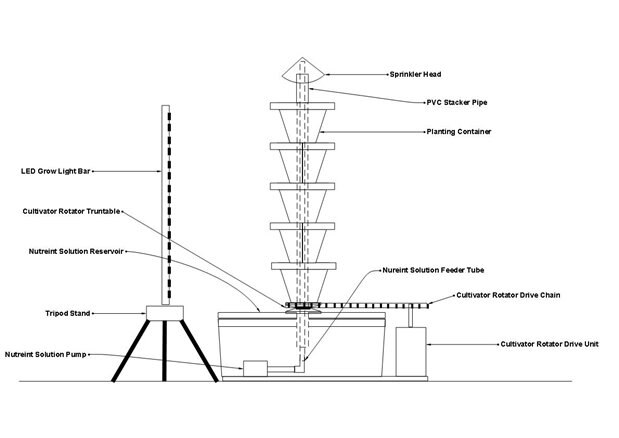
I have a load, my cultivator unit, that will be about 3' - 4' tall, maybe 12" to 18" in diameter and weigh between 20 and 40 lbs. The whole thing will be mounted on a lazy susan style turntable. The plan is to have a gear or pulley at the bottom that will be used with a hight torque stepper motor, and chain or belt, to rotate the cultivator. I'm using a stepper motor because they are pretty efficient and can be controlled very easily at very slow speeds. I want the rotation speed to be maybe 3 to 4 revolutions per day. A stepper would work well for this I think.


I have no idea how to properly size the motor. I see them speced at anywhere from 10s of oz-in to 1000s of oz-inches of torque. I get the concept of torque being rotational force. And that required torque has to do with acceleration time up to the desired RPM. But I have no idea how to relate this to my requirements.


I'm a 'puter software with some dangerous electronics knowledge guy! HELP!!! And feel free to tell me this just a stupid idea and I should be using a washing machine motor or something if that's the case.


For reference, here's a drawing of the rig. Note the drive at the bottom right. Please excuse the misspelled labeling. I haven't gotten around to correcting it yet. lol...

 

image

  • Sign in to reply
  • Cancel

Top Replies

  • mcb1
    mcb1 over 10 years ago in reply to RWReynolds +2
    RWReynolds It looks like your design is coming together. Two comments. The stepper I linked to, Terry made this comment. This means your pulse number might be lower. (half) With the geared output you already…
  • Former Member
    Former Member over 9 years ago in reply to jw0752 +2
    Well, I received my 390mm dia lazy-susan a while back (image attached) but it'll sit in a corner some more yet. Reading lots that I hadn't been aware of e.g "inertia-matching" it seems direct-coupling…
  • clem57
    clem57 over 10 years ago +1
    Same here RWReynolds , but try this calculator for gear reduction to decrease speed Mechanical Gear Reduction Calculator C Edit: How about placing LED's around and turning on/off the set you want? Just…
  • RWReynolds
    RWReynolds over 10 years ago

    OK, I wanted to drop this here just for consistency. Hopefully folks will get notifications and check it out.


    I think I've worked out the my rotator design. If the motor mcb1 recommended works then that drops the price from $30 + controller board to $6 for the motor and controller board. Thanks mcb1!


    Just as a side note: I've found less expensive LED grow light bars as well. I love it when the price of a project goes down. image


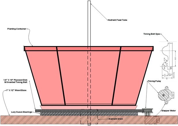
    Here's my design for the rotator. All this will be in the updated detailed design document on my next blog post.


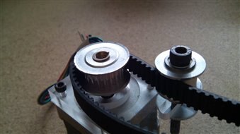
    A little explanation... The 1/4" X 10" plywood disk will have standard GT2 6mm timing belt inverted and fastened to the outer edge. This will form a timing gear if you will. The timing pulley on the stepper will be pressed up against the "timing" disk. Who knows, maybe it'll work? I've calculated that around 40,000 pulses will rotate the turntable once. Honestly, I don't know what would be optimum but just for the sake of argument let's say 4 revulotuins per day. That's 160,000 pulses per day/86,400 sec = 1.9 pulses per sec.  I think the MCU will handle that, no matter how I may decide to split all that up. My main concerne is that the whole system is stable enough so that the gear and pulley remain in contact all the time. The Lazy Susan bearings are rated at 750lbs so it should be plenty stable. But getting the timing disk and Lazy Susan bearings centered to each other is super critical, so we'll see. If not then I have a backup plan to move the motor back and use an actual tensioned timing belt around the timing disk and pulley. I just want to see my wonky inverted timing disk work though.image


    image

    • Cancel
    • Vote Up +1 Vote Down
    • Sign in to reply
    • Cancel
  • balearicdynamics
    balearicdynamics over 10 years ago in reply to RWReynolds

    Hi, I have played in different projects with timing belts in similar configuration and the mechanic scheme is correct. The only thing that may improve is an external tensing pulley that will be pressed on the belt when it is in position and locked with a screw on the axis. I have found this very useful for final regulation when setting all and helpful to keep in place

    • Cancel
    • Vote Up +1 Vote Down
    • Sign in to reply
    • Cancel
  • RWReynolds
    RWReynolds over 10 years ago in reply to balearicdynamics

    Thanks for the input Enrico.


    The drawing in my post is based on a beltless design. The timing gear and pulley are actually in contact with each other. But I don't know if I can build the mechanism accurately enough to achieve that. So, there's a backup plan to slide the motor back a few inches and incorporate a belt. In that case, I will definitely take your advice. I have already located the parts for a small tensioning system. A single small timing pulley and a tensioner spring should do the trick.


    Cheers,

    Rick

    • Cancel
    • Vote Up 0 Vote Down
    • Sign in to reply
    • Cancel
  • balearicdynamics
    balearicdynamics over 10 years ago in reply to RWReynolds

    Hi Rick,


    thank you for the answer. The reason I will use in a case like this a timing belt is for the smooth moving respect the direct traction, always speaking of very slow moving. Anyway, if it is helpful for you I attach an image showing how I have applied the timing belt solution, in a very cheap way.


    Just another question: how is done the mechanics of the rotating base? To you use a central axis with a ball bearing or a recirculating ball bearing? I suppose that the rotating base should support a considerable weight.


    image

    Cheers, Enrico.

    • Cancel
    • Vote Up +1 Vote Down
    • Sign in to reply
    • Cancel
  • RWReynolds
    RWReynolds over 10 years ago in reply to balearicdynamics

    Thanks Enrico.


    Is that tension pulley spring loaded?


    I have attached a picture of the lazy Susan bearing. It's rated at 750lbs so it should more than do the job. I'm expecting the fully loaded tower to be no more than 40 to 50 pounds.

    • Cancel
    • Vote Up 0 Vote Down
    • Sign in to reply
    • Cancel
  • balearicdynamics
    balearicdynamics over 10 years ago in reply to RWReynolds

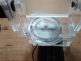
    Hi Rick, I had to reread about the lazy Susan bearing. As a matter of fact I discovered that I have done the same for a camera rotation base. But I had not idea of what was the name image I attach here a picture just to explain what I mean. The principle is the same and testing it I saw that is very good for stability and weight support. In my case it was smaller and more precise but the principle it is almost the same.

    image

    Instead the push pulley is not with tension. I have read - before buying - then directly tested that as a matter of fact the timing belts are almost like gears with very few flexibility and they didn't tend to loose their tension in time. So after placing the engine and the belt, the pulley is adjusted for the right pressure then the axis is locked with a self-locking nut.

    • Cancel
    • Vote Up +1 Vote Down
    • Sign in to reply
    • Cancel
  • RWReynolds
    RWReynolds over 10 years ago in reply to balearicdynamics

    Wow... You put together your own bearing. That's just cool. I wish I had time and the mobility to do that. But, for this project I am using off-the-shelf parts for just about everything. Except for a couple of mods here and there.


    For the beltless design my only concern with the timing belt is this. I am going to be stretching the belt backwards around the diameter of the 10" disk. I know this will stretch the teeth of the belt apart by some degree. I hope that the 2mm pitch pulley still engages the belt teeth correctly. If not I may have to increase the pitch of the pulley.


    In the belted design I think that the timing belt will mesh correctly with the disk belt because it will be somewhat flexible.

    • Cancel
    • Vote Up 0 Vote Down
    • Sign in to reply
    • Cancel
  • balearicdynamics
    balearicdynamics over 10 years ago in reply to RWReynolds

    The belt is few flexible but not so much to create a serious difference between two teeth so I think it is almost meaningless for the movement. Obviously all depends on how much do you need to stretch the belt. But in theory your disk perimeter should be a multiple of the teeth spacing, +/- 1/10 teeth. In my opinion you should try and if it is the case you can lathe very few the disk circumference just to reduce the stretching. I have no idea of what kind of timing belt you are using and the teeth step (the distance between two teeth). Take in account that the shaft gear and the belt gear are not perfectly angular as the physics of the movements transforms a linear movement in rotational movement; to maintain a continuous contact between the two teeth series the gear is rounded, not perfectly angular.


    If you can give me some more information on the kind of belt maybe we can check but the most important parameter is the distance you should stretch the two belt ends.


    Enrico

    • Cancel
    • Vote Up +1 Vote Down
    • Sign in to reply
    • Cancel
  • saturnv
    saturnv over 10 years ago

    Rick, the relationship for rotations, or revolutions is gear ratio. For example, if you want 4 rotations of your cultivator per day that means you want ONE rotation every SIX hours, 1/2 rotation every 3 hours or 1/4 rotation every 1.5 hours. Normally you would want a gear ratio between your cultivator base size and your motors pulley size. However, since you're going to use stepper motors,  all you should need to do software-wise is make use of timing parameters to step the turntable once every 6 hours. Using wait, if/the, for, or pause commands or some other variable to reference the passing of time should work for you. For example is you want it to turn 1/4 turn, have it 'sleep for 5400 seconds (3600 secs/hr * 1.5 hrs=5400 seconds). Do that 16 times via an "if' or "while' type statements and your turntable will rotate 4 times in a 24 hour period. It's all about the math!

    • Cancel
    • Vote Up +1 Vote Down
    • Sign in to reply
    • Cancel
  • RWReynolds
    RWReynolds over 10 years ago in reply to saturnv

    Thanks for the info Michael...


    I think I have it worked out now. The control application will just be a simple state machine based on "the big loop". Reading sensors, performing control functions and logging them, via the radio, back to the central control/monitor system. I think control functions and reading the sensors should be very lightweight. There's no sensor that needs to be read more than once a second, and that's probably overkill. As the EZR32WG has some very low power modes available I plan to have it sleep most of the time and wake up only periodically to run the loop. The central control/monitor will have the ability to wake the crowing area system up at any time and instruct it to read sensors and/or perform control functions.


    I'll have to workout all the timing and pulse count once I have the MCU in hand and the rotator is completed. So far my calculations go like this... My stepper motor is geared and requires 4096 pulses per revolution. There is about a 10:1 ration between the timing gear, at the turntable, and timing pulley on the stepper motor. That gives me about 41,000 pulses per revolution at the turntable. If I want 4 revolutions per day so that's 164,000 pulses per day. That works out to about 2 pulses per second. So I could just pulse it a couple of times on each wake up cycle. Since the motor is geared it doesn't require power to remain stationary. We'll see.


    Right now I'm waiting on the final parts for the turntable and on the E14 kit. It's all just theory right now. lol...

    • Cancel
    • Vote Up 0 Vote Down
    • Sign in to reply
    • Cancel
<>
element14 Community

element14 is the first online community specifically for engineers. Connect with your peers and get expert answers to your questions.

  • Members
  • Learn
  • Technologies
  • Challenges & Projects
  • Products
  • Store
  • About Us
  • Feedback & Support
  • FAQs
  • Terms of Use
  • Privacy Policy
  • Legal and Copyright Notices
  • Sitemap
  • Cookies

An Avnet Company © 2025 Premier Farnell Limited. All Rights Reserved.

Premier Farnell Ltd, registered in England and Wales (no 00876412), registered office: Farnell House, Forge Lane, Leeds LS12 2NE.

ICP 备案号 10220084.

Follow element14

  • X
  • Facebook
  • linkedin
  • YouTube