

For any project where something moves, there is almost always an electric motor involved somewhere in the system. In this project, Milos Ras̆ić takes a deep dive into how brushed DC motors are actually driven, why many off‑the‑shelf modules fall short, and what it looks like to design a fully custom, open‑source dual motor driver PCB from scratch with real robotics use in mind.
Rather than jumping straight to a finished board, Milos deliberately walks through his entire engineering process: defining requirements, selecting components, validating assumptions, designing the PCB, assembling it methodically, debugging real‑world mistakes, and finally building firmware and a custom GUI to make the hardware genuinely usable. As he explains early on, this board is intended to become the low‑level motor control layer for his future robotic platforms, not a one‑off demo.
“I wanted to design my own custom PCB with certain requirements… and also take this chance to show you my whole engineering process – from the idea, through evaluation, and then iterating into the next versions.”
How Do Motor Drivers Work?
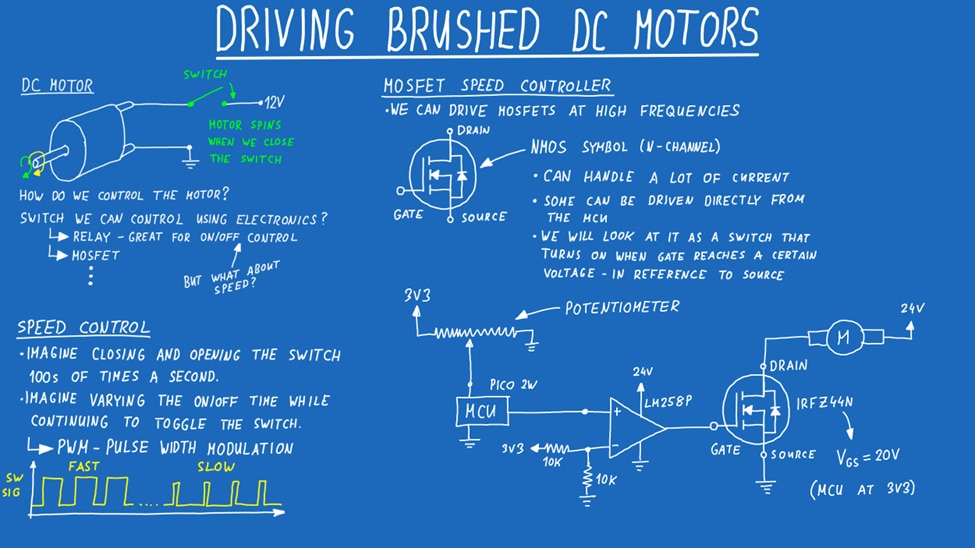
Milos begins by stripping motor control down to its simplest form. A brushed DC motor will spin if you connect it directly to a power source – effectively simulating a battery. That approach works, but only in the most basic sense. There’s no speed control, no direction control, and no feedback. The next step is switching the motor on and off rapidly. By toggling a switch hundreds or thousands of times per second and varying how long it stays on versus off, you create Pulse Width Modulation (PWM). A wider pulse delivers more energy to the motor; a narrower pulse reduces it.
To do this electronically, Milos demonstrates a simple N‑channel MOSFET circuit. A MOSFET behaves like a fast electronic switch and is far better suited to high‑frequency PWM than a relay. In his bench example, he uses an op‑amp as a level translator so that a 3.3 V microcontroller can properly drive a MOSFET that expects a much higher gate voltage. This approach works well for speed control, but it has a fundamental limitation: the motor only spins in one direction. As Milos points out:
“There really is no way to switch the direction of the motor driving besides flipping the wires around.”
Direction control requires a different topology altogether.
H‑Bridges and Direction Control
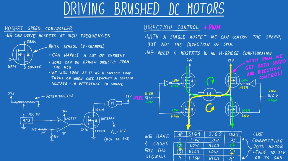
To reverse a motor electronically, you need to flip the polarity of the voltage applied to it. This is achieved using an H‑bridge, which arranges four transistors so current can flow through the motor in either direction.
Milos explains the logic clearly, including the importance of never enabling both transistors on the same side of the bridge at once, which would effectively short the supply. With an H‑bridge and PWM applied to the appropriate control line, you gain full control over both speed and direction. At this point, he references a familiar module:
“If you’ve ever played around with an Arduino… you’ve probably used an L298N.”
While popular, the L298N relies on BJTs rather than MOSFETs, making it inefficient and unsuitable for higher‑power applications. This inefficiency, combined with voltage drop and heat dissipation, is one of the main motivations for designing a custom solution.
Defining the Requirements
Before touching any schematic software, Milos creates a system requirements list. This list drives every design decision that follows and serves as a reference during revisions.
Key requirements include:
- Driving two brushed DC motors
- A single, compact PCB with the MCU onboard
- At least 5 A continuous current per motor
- A wide input voltage range (targeting 5 V–36 V, with ambitions beyond)
- Clean, stable 3.3 V power for measurement and control
- Current sensing for each motor
- Extensive connector support for daisy‑chaining boards
“The requirement list is a really nice thing to have since it keeps you on track… and when you do revisions, you can fall back onto this and see if you’ve missed something.”

Electronics and Power Architecture
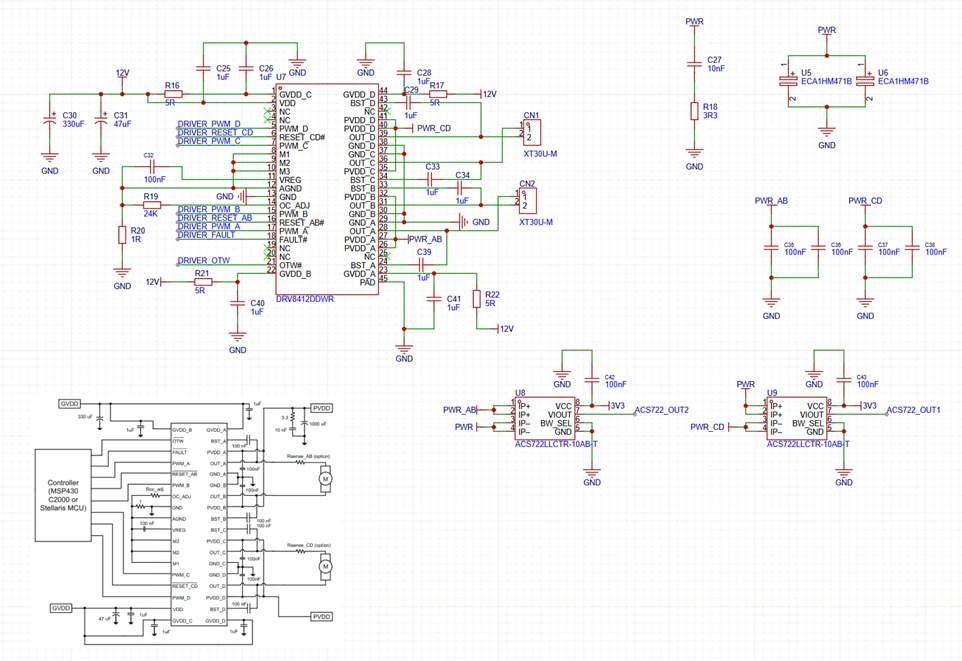
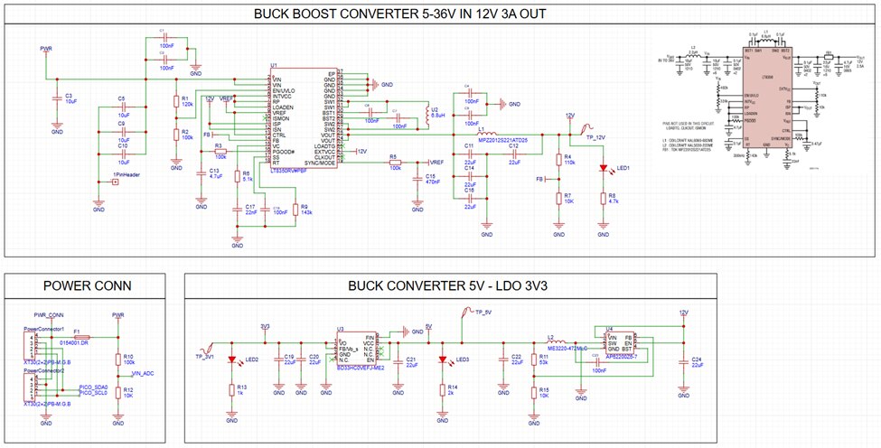
With the requirements defined, Milos starts with the most critical component: the motor driver IC. After filtering options and reviewing datasheets, he selects a Texas Instruments dual H‑bridge driver capable of handling the required current in a compact package. That choice introduces an immediate design challenge: the driver requires a stable 12 V supply, regardless of the board’s input voltage. To solve this, Milos implements a buck‑boost converter, allowing the board to operate from roughly 4 V up to 40 V while still generating a clean 12 V rail.
From there, power is stepped down in stages:
- Buck‑boost → 12 V
- Buck → ~5 V
- LDO → 3.3 V
This staged approach reduces noise on the 3.3 V rail, which is critical for ADC measurements, current sensing, and encoder feedback.
“The LDO is like a smart resistor… you get a clean nice output of 3.3 V in the end.”
For current sensing, Milos chooses Hall‑effect current sensors rather than shunt resistors, valuing their stability and isolation.
The board also includes:
- Input voltage measurement via a divider
- A fuse for protection
- XT‑style power connectors with additional communication pins
- Switchable I²C pull‑ups
- An RGB status LED controlled over I²C
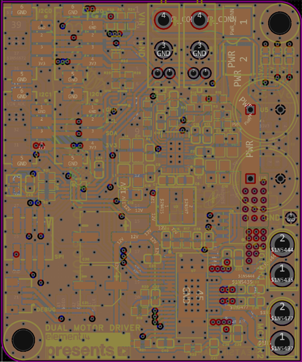
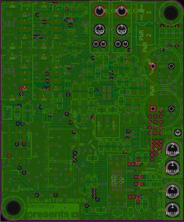
PCB Layout and Physical Design
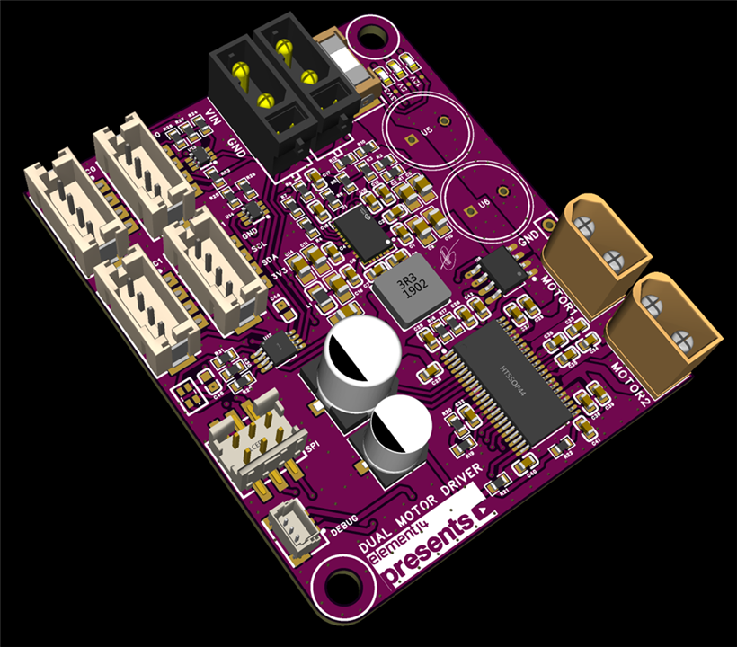
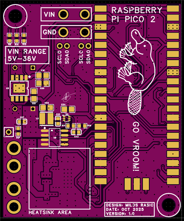
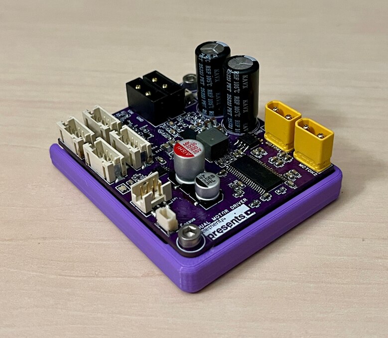
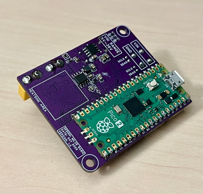
Once the schematics are complete, Milos moves on to PCB layout. The final board measures 50 mm × 60 mm and uses a 4‑layer stack‑up (SIG–GND–GND–SIG). Much of the board size is dictated by the Raspberry Pi Pico 2 module, which Milos mounts directly rather than designing a custom RP2040 layout for this revision.
The PCB is dense but carefully partitioned:
- Power conversion sits centrally
- High‑current motor paths are kept short and wide
- Sensitive analog and MCU sections are isolated
- Large copper pours and a defined heatsink area help with thermal management
The result is a compact yet expandable board, complete with Milos’ Platypus mascot and a clear “GO VROOM!” silkscreen reminder of its purpose.
Assembly, Checklists, and Debugging
Rather than soldering everything at once, Milos relies on a soldering and testing checklist, assembling and validating the board in stages:
- Buck‑boost converter
- Buck converter
- LDO
- Motor driver
- MCU and peripherals
This method quickly pays off. While the board works almost entirely as intended, two errors are discovered:
- An incorrect footprint for one IC, requiring hand‑extended pins
- A buck converter enable pin that could not tolerate 12 V, repeatedly destroying the IC
“Because of the checklist, I managed to identify what was wrong and why… otherwise I would’ve probably burned a lot more chips.”
Milos documents these issues in an errata sheet, reinforcing the idea that revision‑friendly design is part of good engineering.
On the software side, the board runs firmware that deliberately avoids high‑level robotics logic. Instead, it exposes a command‑driven motor control interface over USB, UART, and I²C.
The firmware is structured around several key components:
-
DualMotorController
Handles PWM generation, fault detection, current measurement, and direction control. -
ClosedLoopController
Implements manual control, speed PID, and position PID modes. -
As5600Encoder
Interfaces with the AS5600 magnetic encoder, handling wrap‑around, filtering, and unit conversions. -
CommandProcessor
Parses human‑readable ASCII commands (M‑codes) and compact binary frames.
Notably, PWM is capped at 95% duty cycle (
PWM_ACTIVE_MAX = 950) to ensure bootstrap capacitors in the motor driver remain charged – a subtle but important hardware‑aware firmware detail. Speed and position control are implemented using the PidController class, with tunable gains, integral limits, and output clamping.In practice:
- Speed control works best as a PI controller, since derivative action introduces too much noise at the encoder sampling rate.
- Position control benefits from P and I terms, with careful tuning to avoid integral wind‑up.
“If you try doing anything with the derivative part, you just get a bunch of noise… so we’ll essentially just use a PI controller instead.”
The firmware also includes:
- Automatic direction self‑checks
- Encoder zeroing
- Gain scheduling hooks for future improvements
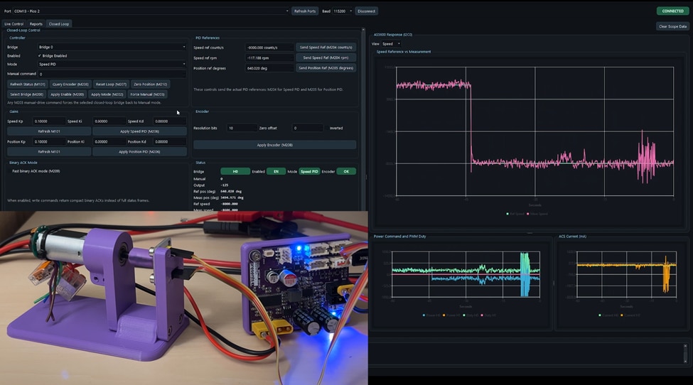
To make tuning and testing practical, Milos builds a custom Python GUI using PySide6. The GUI provides:
- Real‑time plots of speed, position, current, and PWM duty
- Live status indicators for faults and thermal warnings
- Manual control sliders
- PID tuning panels
- Encoder configuration and zeroing
- Binary and ASCII telemetry support
This interface turns the board from “just hardware” into a usable development tool and makes PID behavior visually intuitive.
Finished Project and What’s Next
In the end, Milos considers the project a success:
“I’m really happy with how this PCB turned out… it’s bigger than the module we started with, but it’s a lot more capable.”
The board meets nearly all of its original requirements, and the few shortcomings are clearly documented. Future plans include:
- Integrating multiple boards into a robotic platform
- Supporting mecanum wheel control
- Further refining PID tuning and control abstractions
- Iterating the PCB with lessons learned from revision one
Supporting Links and Files
Bill of Materials
| Product Name | Manufacturer | Quantity | Buy Kit |
|---|---|---|---|
| LT8350 | ANALOG DEVICES | 1 | Buy Now |
| Inductor XAL6060-682MEC | COILCRAFT | 1 | Buy Now |
| Resistor 0603 270k - MCWR06X2703FTL | MULTICOMP PRO | 1 | Buy Now |
| Resistor 0603 100k - MCMR06X1003FTL | MULTICOMP PRO | 4 | Buy Now |
| Capacitor 22uF 0805 25V - CL21A226MAYNNNE | SAMSUNG | 9 | Buy Now |
| Connector PCB 2+2 - MP011760 | MULTICOMP PRO | 2 | Buy Now |
| Connector Cable 2+2 - MP011759 | MULTICOMP PRO | 2 | Buy Now |
| 3V3 LDO - BD33HC0VEFJ-ME2 | ROHM | 1 | Buy Now |
| Heatsink LTN20069 | WKEFIELD THERMAL | 1 | Buy Now |
| Resistor 0603 - 1k | MULTICOMP PRO | 4 | Buy Now |
| Resistor 0603 - 2k | MULTICOMP PRO | 1 | Buy Now |
| Resistor 0603 - 4k7 | MULTICOMP PRO | 5 | Buy Now |
| Inductor - ME3220-472MLC | COILCRAFT | 1 | Buy Now |
| Capacitor 4.7uF 0603 | MURATA | 1 | Buy Now |
| Resistor 0603 5k1 | MULTICOMP PRO | 1 | Buy Now |
| Resistor 0603 10k | MULTICOMP PRO | 5 | Buy Now |
| Capacitor 0805 10uF 50V | MURATA | 4 | Buy Now |
| Capacitor 0603 22nF | SAMSUNG | 1 | Buy Now |
| Capacitor 0603 100nF 50V | SAMSUNG | 17 | Buy Now |
| Resistor 0603 143k | MULTICOMP PRO | 1 | Buy Now |
| Capacitor 0603 470nF | SAMSUNG | 1 | Buy Now |
| Fuse with Fuse Holder SMD - 0154010.DR | LITTELFUSE | 1 | Buy Now |
| Buck Converter IC - AP62200Z6-7 | DIODES INC | 1 | Buy Now |
| LED Red 0603 | MULTICOMP PRO | 1 | Buy Now |
| LED Green 0603 | MULTICOMP PRO | 1 | Buy Now |
| LED Blue 0603 | MULTICOMP PRO | 1 | Buy Now |
| Inductor Ferrite Bead MPZ2012S221ATD25 | TDK | 1 | Buy Now |
| Resistor 0603 1R | MULTICOMP PRO | 1 | Buy Now |
| Capacitor 0603 1uF 25V | SAMSUNG | 7 | Buy Now |
| Resistor 0603 3R3 | MULTICOMP PRO | 1 | Buy Now |
| Resistor 0603 5R | MULTICOMP PRO | 4 | Buy Now |
| Capacitor 0603 10nF 50V | SAMSUNG | 1 | Buy Now |
| Resistor 0603 24K | MULTICOMP PRO | 1 | Buy Now |
| Capacitor 47uF | KEMET | 1 | Buy Now |
| Capacitor 330uF | AISHI | 1 | Buy Now |
| Current Sensor IC - ACS722 | ALLEGRO | 2 | Buy Now |
| Motor Driver IC - DRV8412DDWR | TEXAS INSTRUMENTS | 1 | Buy Now |
| Capacitor 470uF 50V | KYOCERA | 2 | Buy Now |
| Motor Connector - XT30 | DFROBOT | 2 | Buy Now |
| SPI/GPIO Connector - PCB | AMPHENOL | 1 | Buy Now |
| SPI/GPIO Connector - Cable | AMPHENOL | 1 | Buy Now |
| SPI/GPIO Connector - Pins | AMPHENOL | 6 | Buy Now |
| RGB LED | WURTH ELEKTRONIK | 1 | Buy Now |
| Debug Connector | JST | 1 | Buy Now |
| LED Driver IC | NXP | 1 | Buy Now |
| Raspberry Pi Pico 2 | RASPBERRY-PI | 1 | Buy Now |
| PullUp Resistor Switch RN2905 | TOSHIBA | 2 | Buy Now |
Additional Parts
| Product Name | Manufacturer | Quantity |
|---|---|---|
| 2mm pitch JST style SMD connectors | N/A | |
| Blank PCBs | N/A | |
| Brushed DC Motors | N/A | |
| AS5600 Encoder Module | N/A | |
| WAFER-PH2.0-4PLB | N/A | 4 |


