

Join Milos as he builds a simple SCARA robot arm and explores the fundamentals of robotics through practical engineering. From robot arm configurations and direct and inverse kinematics to firmware development, Python control software and motion planning, the project shows how mathematical concepts translate into real-world movement. Using a Raspberry Pi Pico 2 W, hobby servos and a custom GUI, the robot is able to move to coordinates, follow trajectories and even draw shapes, providing a hands-on introduction to robotic control systems, calibration and coordinate-based motion. Watch along and you can find the supporting files below.
Time to Strong-Arm Electronics!
After exploring electronics, mechanics, control engineering, microcontrollers and robotics fundamentals in the previous instalments of this introduction to robotics series, Milos moves from theory into a practical build. Rather than discussing robotics from an abstract perspective, this project demonstrates how those concepts come together in a working machine: a compact SCARA robot arm capable of moving to coordinates, visualising kinematics and even drawing shapes.
The aim is not to build the most accurate robot arm possible. Instead, the project focuses on creating something approachable, affordable and educational. As Milos explains:
“This is the main goal of this course is to keep it as simple as possible so for people that are doing anything like this for the first time.”
By keeping the design simple, the project becomes an effective platform for understanding the principles that underpin industrial robots, from coordinate systems and kinematics through to feedback, calibration and motion control.
If you're new to robotics, it is worth reviewing the earlier episodes:
Understanding Robot Arms and Kinematics
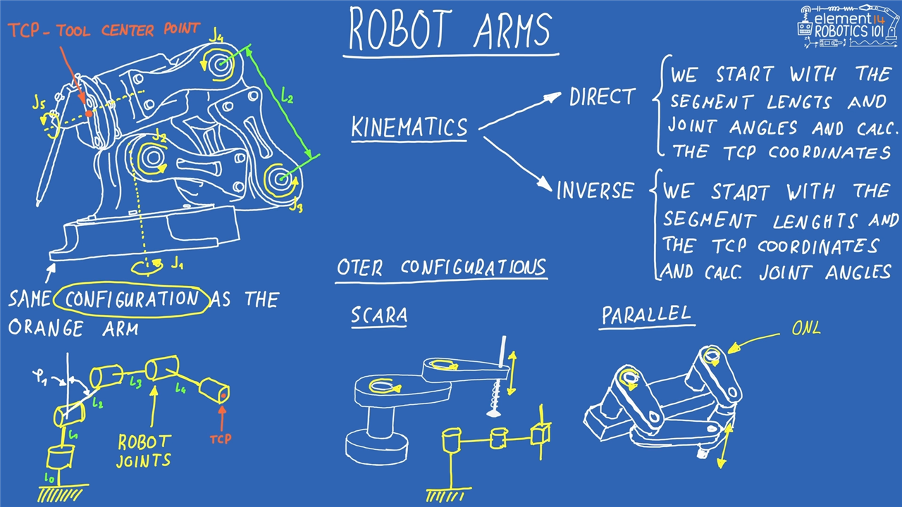
Before touching any hardware, Milos begins with one of the most important concepts in robotics: robot arm configuration. Whether a robot is a compact desktop arm, an industrial manipulator or a SCARA system, every robot arm can be described by its joints, the links connecting those joints and the position of its tool centre point (TCP).
Once the joint positions and link lengths are known, it becomes possible to describe the entire robot mathematically. This is where kinematics enters the picture.
As Milos explains:
“When we talk about robot arms, we're usually interested in kinematics. That means direct kinematics and inverse kinematics.”
Direct kinematics starts with known joint angles and link lengths and calculates the position of the TCP. Inverse kinematics takes the opposite approach. A target position is specified first, and the required joint angles are calculated afterwards.
“Maybe we want to place the tool at a certain coordinate. To do that we need to calculate all of the angles in the joints.”
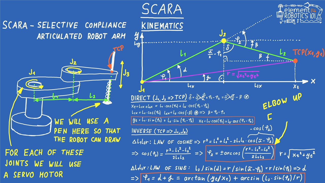
The robot built in this project uses a SCARA (Selective Compliance Articulated Robot Arm) configuration. Unlike a traditional articulated robot arm with many joints, a SCARA robot uses two rotary joints operating in a plane and a simple actuator for vertical movement.
This simplified structure makes it ideal for learning robotics because the mathematics remains approachable while still introducing the same principles used on larger industrial systems.
Milos also highlights an important concept encountered in real robotic systems: multiple inverse kinematics solutions.
“We can reach the same point with two distinct configurations.”
These are commonly referred to as elbow-up and elbow-down configurations. Both reach the same TCP coordinate while positioning the robot differently.
The project also introduces singularities. In the fully extended position, the robot loses one of its available configurations and can only reach that point in a single orientation.
“The arm is completely stretched where we would have a singularity position.”
Anyone interested in exploring these concepts further can find additional resources within the element14 Learning Centre, including:
Hardware Design
The hardware reflects the project's educational focus. The goal was to minimise complexity without removing important robotics concepts.
At the centre of the system is the Raspberry Pi Pico 2 W, a compact microcontroller with more than enough processing power to handle servo control, communications and feedback acquisition.
“It's a brand new microcontroller, it's more than powerful enough for this and it's a small form factor.”
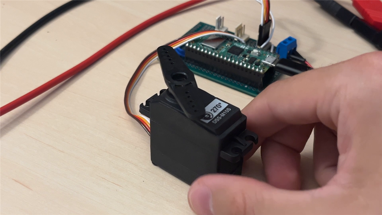
Three servo motors are used. Two control the primary arm joints while the third operates the pen-lift mechanism.
Rather than using stepper motors or brushless motors with dedicated drivers, Milos chose standard RC servos because they are inexpensive, easy to source and straightforward to control.
“Why not use stepper motors or BLDC motors? One thing, simplicity.”
Two of the servos also provide analogue feedback signals. These are connected directly to the Pico's ADC inputs, allowing the software to monitor actual joint movement and compare commanded positions with measured positions.
“This is just an additional line that will feed the Pico ADC so we can measure the actual angle and get some graphs back.”
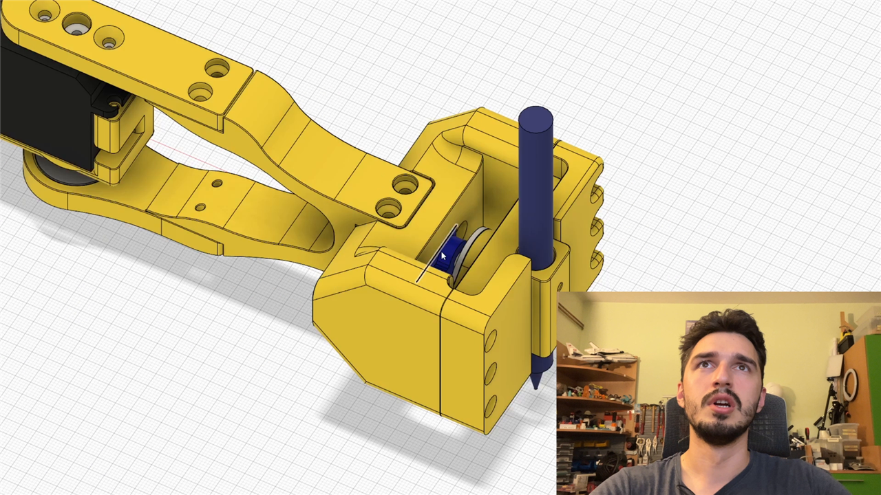
Mechanically, the arm was designed in Fusion 360 and printed in PLA. The design uses two equal-length links measuring 150mm each.
“Both links are at 150 millimeters which was my goal so we can keep them as easy as possible.”
The drawing mechanism is equally simple. An SG90 servo lifts and lowers a pen through a small cam arrangement, enabling the robot to trace paths onto paper.
All CAD resources, including STEP and STL files, are available for builders wishing to recreate or modify the project.
Firmware and Control Architecture
The software architecture is intentionally split into two layers.
The Pico firmware acts primarily as a hardware interface, while the more computationally demanding robotics calculations are performed on the PC.
“The heavy lifting for the robot arm will be actually done on the computer.”
Communication takes place over a serial connection using a command structure inspired by G-code.
As Milos explains:
“The commands pretty much resemble G-code style commands.”
Commands such as G0 and G1 provide rapid and smooth movement control, while calibration, streaming and configuration commands allow deeper interaction with the robot.
The firmware itself documents this clearly:
G0 A B Z        - move in degrees
G1 A B Z [F]    - move in degrees
G28             - home
G90             - report position
M10             - ADC snapshot
M11             - start streaming
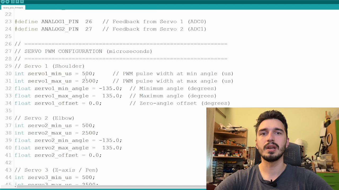
Servo calibration and motion tuning are configurable directly from the firmware. For example:
float move_speed = 5.0;
int move_delay_ms = 20;
These settings determine how smoothly the servos move between commanded positions.
The firmware also incorporates safety functions such as emergency stop support:
M112 - Emergency stop / detach all servos
M113 - Re-attach servos
This allows the robot to be safely disabled and recovered during experimentation.
The Python GUI and Practical Robotics
The second part of the software stack is a substantial Python-based GUI created specifically for learning robotics concepts.
Rather than relying entirely on terminal commands, the interface provides visual tools for understanding the relationship between coordinates, joint angles and robot motion.
“The graphical user interface communicates with the robot arm.”
Joint sliders allow direct manipulation of servo positions, while a Cartesian control system lets the user command positions using X-Y coordinates.
“The GUI allows the user to send xy coordinates which get recalculated into servo angles using inverse kinematics.”
A dedicated kinematics learning section was included in the software. The Python application features:
- Forward and inverse kinematics demonstrations
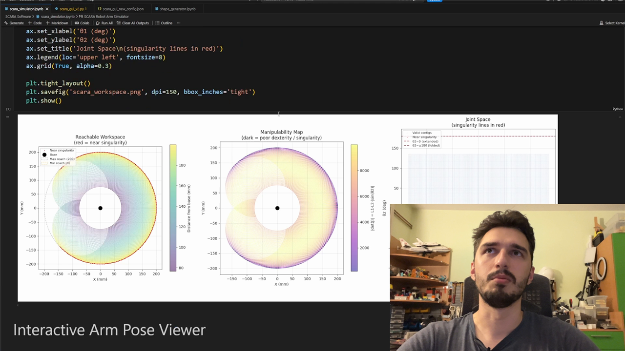
- Workspace visualisation
- Joint tracking plots
- Feedback monitoring
- CSV path playback
- Calibration tools
- Teach mode functionality
The source code describes the goal directly:
Kinematics Lab tab dedicated to teaching FK and IK side-by-side with the underlying formulas.
The software also visualises both elbow-up and elbow-down inverse kinematic solutions, helping users understand why multiple solutions exist for many reachable points.
For those looking to strengthen their software skills, element14's Learning Centre also provides:
Drawing Paths with CSV Trajectories
Once direct control was working, the next challenge was creating repeatable motion.
The GUI includes a path playback system capable of loading CSV files containing coordinate lists.
“We can load up a custom CSV with a bunch of points to which the robot arm should go and we can trace different outlines.”
To simplify shape creation, Milos also created Python tools capable of generating geometric paths automatically.
“It generates your CSV shape in a bunch of dots and when you load that in the graphical user interface your arm will actually replay that path.”
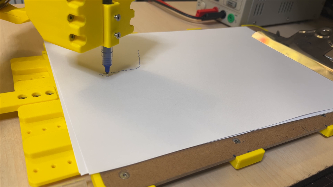
This transforms the robot from a coordinate demonstration into a machine capable of producing recognisable drawings.
Testing the Robot Arm
With the mechanical assembly complete and the software operating correctly, the final stage was testing.
Initial tests focused on simple joint movement and home positioning. The graphical representation matched the physical robot closely, demonstrating that the kinematic calculations were behaving correctly.
“You can see that we are getting the movements that mimic what's also happening on the user interface.”
The inverse kinematic controller proved particularly successful.
“If we go and say move to xy you can see how it moves rapidly.”
As expected, the limitations of hobby-grade servos quickly became apparent.
“The arm moves a lot and that's the main issue with servos like this, they just aren't that accurate.”
However, the educational value remained high.
“For the price and for the simplicity of how easy they are to use they are a pretty good deal.”
Path playback tests produced some impressive results, including stars and even an element14 logo. Although the robot occasionally exhibited visible oscillation, Milos identified exactly why:
“It actually stops between each point so it's not as accurate as it could be.”
Future improvements could incorporate more advanced path-planning methods and look-ahead algorithms to smooth motion between waypoints.
“You can do this much better with proper path planning look forward algorithms that would make the actual path for both the servos smooth.”
From Theory to Practical Robotics
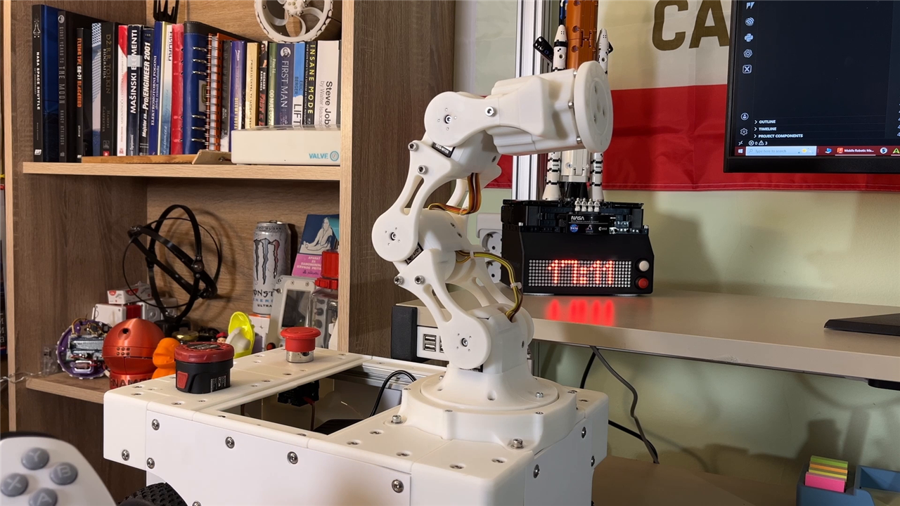
This build demonstrates one of the most rewarding aspects of robotics: seeing mathematical models become physical motion.
Throughout the project, concepts such as coordinate systems, direct kinematics, inverse kinematics, servo control, calibration and feedback move from sketches on a whiteboard into a functioning machine.
“We can see some connection between actual theory with all of those equations that you've seen in the beginning and with actual real world results.”
For newcomers, the project provides an approachable way to understand how robot arms operate. For more experienced makers and engineers, it offers a solid foundation for exploring advanced topics such as motion planning, PID control, encoder feedback and ROS integration.
Most importantly, it demonstrates that robotics does not need to begin with expensive hardware or industrial equipment. With a Raspberry Pi Pico 2 W, a handful of servos, some printed parts and a willingness to experiment, it is possible to build a robot that brings the mathematics of robotics to life.
Supporting Files and Links
- https://community.element14.com/learn/learning-center/
- Motor Control: Motor Drive Control for Makers
- The Basics of Microcontrollers
- An Introduction to Programming with Python
- Essentials of Robot Operating System 2
- PID Control, Motion Profiles and ROS Explained - An Introduction to Robotics
- Building the Foundations of Your First Robot - An Introduction to Robotics
Bill of Materials / Parts Used
| Product Name | Manufacturer | Quantity | Buy Kit |
|---|---|---|---|
| Servo Motor SER0044 | DFROBOT | 2 | Buy Now |
| Filament MC002555 | MULTICOMP PRO | 1 | Buy Now |
| RASPBERRY-PI PICO 2 | RASPBERRY PI | 1 | Buy Now |
| Servo Motor SER0039 | DFROBOT | 1 | Buy Now |
Additional Parts
| Product Name | Manufacturer | Quantity |
|---|---|---|
| M3 machine screws | ||
| Perfboard | ||
| Wires |


