element14 Community
element14 Community
    Register Log In
  • Site
  • Search
  • Log In Register
  • Community Hub
    Community Hub
    • What's New on element14
    • Feedback and Support
    • Benefits of Membership
    • Personal Blogs
    • Members Area
    • Achievement Levels
  • Learn
    Learn
    • Ask an Expert
    • eBooks
    • element14 presents
    • Learning Center
    • Tech Spotlight
    • STEM Academy
    • Webinars, Training and Events
    • Learning Groups
  • Technologies
    Technologies
    • 3D Printing
    • FPGA
    • Industrial Automation
    • Internet of Things
    • Power & Energy
    • Sensors
    • Technology Groups
  • Challenges & Projects
    Challenges & Projects
    • Design Challenges
    • element14 presents Projects
    • Project14
    • Arduino Projects
    • Raspberry Pi Projects
    • Project Groups
  • Products
    Products
    • Arduino
    • Avnet Boards Community
    • Dev Tools
    • Manufacturers
    • Multicomp Pro
    • Product Groups
    • Raspberry Pi
    • RoadTests & Reviews
  • About Us
  • Store
    Store
    • Visit Your Store
    • Choose another store...
      • Europe
      •  Austria (German)
      •  Belgium (Dutch, French)
      •  Bulgaria (Bulgarian)
      •  Czech Republic (Czech)
      •  Denmark (Danish)
      •  Estonia (Estonian)
      •  Finland (Finnish)
      •  France (French)
      •  Germany (German)
      •  Hungary (Hungarian)
      •  Ireland
      •  Israel
      •  Italy (Italian)
      •  Latvia (Latvian)
      •  
      •  Lithuania (Lithuanian)
      •  Netherlands (Dutch)
      •  Norway (Norwegian)
      •  Poland (Polish)
      •  Portugal (Portuguese)
      •  Romania (Romanian)
      •  Russia (Russian)
      •  Slovakia (Slovak)
      •  Slovenia (Slovenian)
      •  Spain (Spanish)
      •  Sweden (Swedish)
      •  Switzerland(German, French)
      •  Turkey (Turkish)
      •  United Kingdom
      • Asia Pacific
      •  Australia
      •  China
      •  Hong Kong
      •  India
      •  Korea (Korean)
      •  Malaysia
      •  New Zealand
      •  Philippines
      •  Singapore
      •  Taiwan
      •  Thailand (Thai)
      • Americas
      •  Brazil (Portuguese)
      •  Canada
      •  Mexico (Spanish)
      •  United States
      Can't find the country/region you're looking for? Visit our export site or find a local distributor.
  • Translate
  • Profile
  • Settings
WorkBench Wednesdays
  • Challenges & Projects
  • element14 presents
  • WorkBench Wednesdays
  • More
  • Cancel
WorkBench Wednesdays
Forum Microcontroller Dev Boards: What features do you like to have (or to add?)
  • Blog
  • Forum
  • Documents
  • Quiz
  • Events
  • Polls
  • Files
  • Members
  • Mentions
  • Sub-Groups
  • Tags
  • More
  • Cancel
  • New
Join WorkBench Wednesdays to participate - click to join for free!
Actions
  • Share
  • More
  • Cancel
Forum Thread Details
  • Replies 21 replies
  • Subscribers 110 subscribers
  • Views 6291 views
  • Users 0 members are here
  • pcb
  • microcontroller
  • arduino
  • pi pico
Related

Microcontroller Dev Boards: What features do you like to have (or to add?)

baldengineer
baldengineer over 2 years ago

image

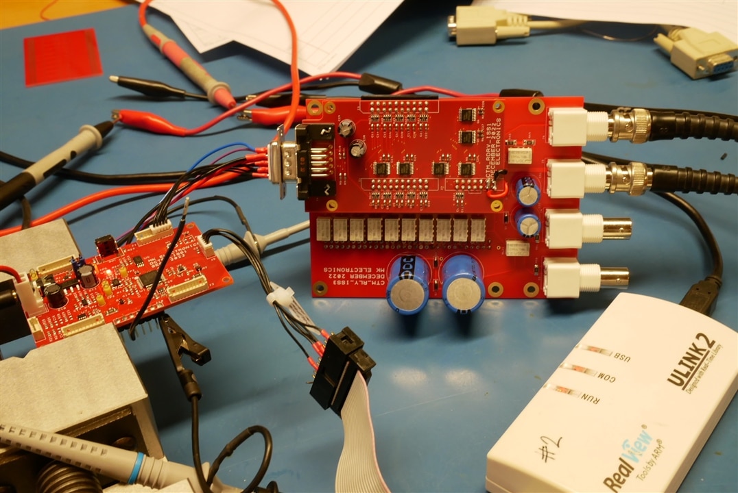
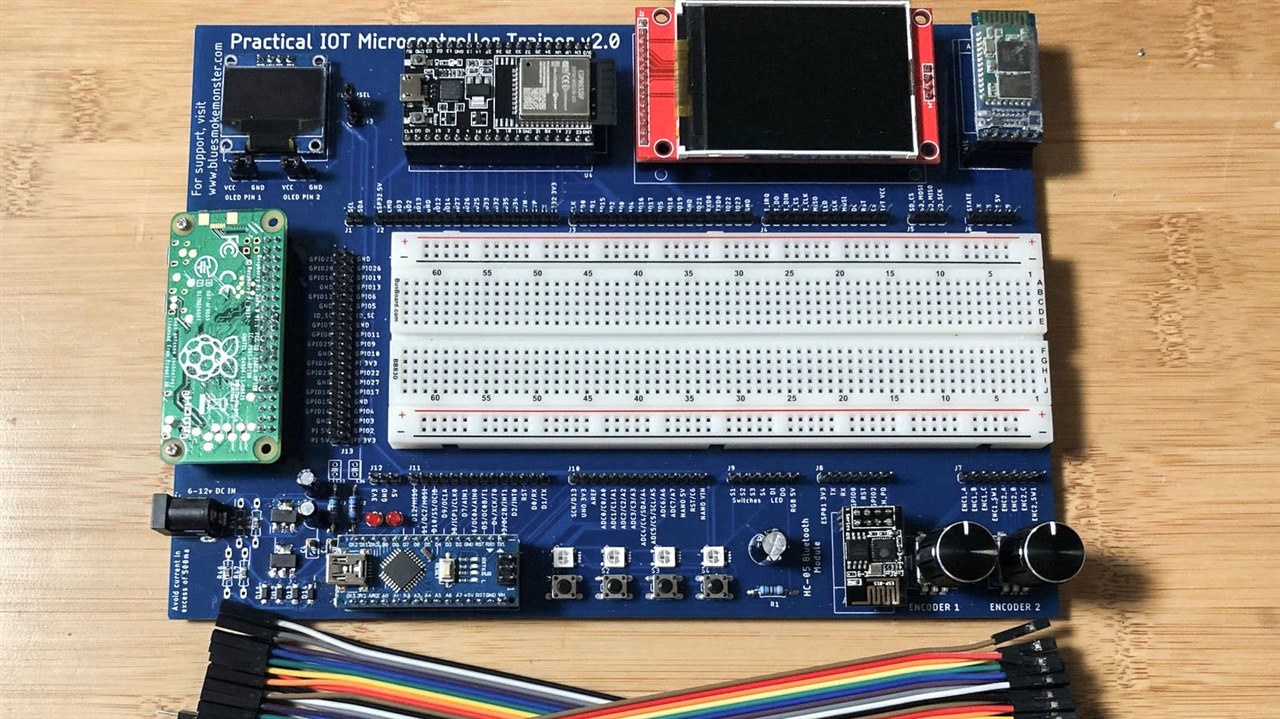
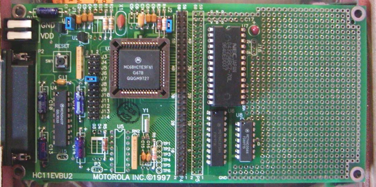
A couple of weeks ago, I bribed shabaz (with coffee) to send me one of his Pi PIco Eurocards. As the name implies, these are a development board for the Pi Pico / RP2040. In the past, another friend sent me one of his all-in-one microcontroller development boards (pictured above). And I have designed a few boards that had development features on them. Besides those, boards like Adafruit's Feathers or even the iconic Arduino Uno could be considered dev boards. Last, historically, microcontroller manufacturers had elaborate evaluation platforms for their chips.

All of these points made me wonder: what are the features YOU want to see in a microcontroller development board?

image

If we use shabaz's Eurocard, some notable features are:

  • Headers for changing power source (external / Pi Pico / Programmer)
  • Integrated programmer/debugger (RP2040-based Xiao, in this case)
  • Prototype areas for through-hole and surface mount parts
  • SD Card
  • Button
  • LED
  • (and many more)

In addition to features, what tricks or tips have people learned when making a board like this one?

  • Sign in to reply
  • Cancel

Top Replies

  • wolfgangfriedrich
    wolfgangfriedrich over 2 years ago +8
    I just want to point out one feature, which is really nicely done on both of those boards. The markings of connectors and everything else in silkscreen. Pin numbers or signal labels in readable size, also…
  • michaelkellett
    michaelkellett over 2 years ago +7
    Keep it simple. Power supply input, on board regulator and clock. Break out every pin. Serial port, debug programming port. 0.1" headers are good and cheap but sometimesd take up too much room…
  • mayermakes
    mayermakes over 2 years ago +6
    i don't really have requests in stuff that should be on the board, I prefer to have zero clutter or parts that I don't really use in the project present to avoid conflicts and confusion on my part. also…
  • mayermakes
    mayermakes over 2 years ago

    i don't really have requests in stuff that should be on the board, I prefer to have zero clutter or parts that I don't really use in the project present to avoid conflicts and confusion on my part. also I don´t like any customization in routing that require Arduino cores, DTOs or any other compability layer , not even a renumbering of the pins. Everything should work exactly as if I put the bare chip I build upon on a board, NO deviationsm no porting.
    My biggest request is to have Flawless software support OOTB, no special linux derivates that never get updated or proprietary SDKs.
    a simple way without any additonal hardware to flash code / boot (native usb for example is great)
    and absolutelly Open source construction, no proprietary software needed and only Bog standard mainline Linux support on day one. that would be my biggest request.

    • Cancel
    • Vote Up +6 Vote Down
    • Sign in to reply
    • Cancel
  • dougw
    dougw over 2 years ago

    I think of it as 4 levels of dev card, each is useful:

    1. The starting point as Jan Cumps  would say is to breakout every pin of the MCU onto a header and provide enough infrastructure to program and rum.
    2. The next step up for me would be to incorporate standard connectors for standard interfaces. Like USB, UART, SPI + power, I2C + power, Analog + power, digital + power, servo, etc.
    3. The next step up for me would be to incorporate standard connectors for standard peripherals and communication functions. Like a display or HDMI, keypad, Bluetooth, WiFi, audio, video, MIPI, SD, etc.
    4. Then finally more complete but constrained systems that include on-board peripherals like displays, sensors, speakers, keypads, cameras, microphones, etc.

    The difference between level 2 and 3 is that level 2 is mostly adding purpose connectors for MCU functions, where level 3 generally needs support chips or areas for peripherals to reside.

    There might only be 1 type of level 1 module, but as the levels get more complex, the number of variants would increase to accommodate different feature sets.

    I'm not a big fan of breadboard areas on a dev card since it wastes space and I generally use custom PCBs to perform "breadboard" functions.

    If modules try to make a one-size-fits-all solution it ends up to have a lot of wasted resources or it is too costly or it consumes too much power or it is too big.

    • Cancel
    • Vote Up +4 Vote Down
    • Sign in to reply
    • Cancel
  • wolfgangfriedrich
    wolfgangfriedrich over 2 years ago

    I just want to point out one feature, which is really nicely done on both of those boards. The markings of connectors and everything else in silkscreen. Pin numbers or signal labels in readable size, also the grid on the prototyping area.

    TLDR: If there is room, add more text.

    • Cancel
    • Vote Up +8 Vote Down
    • Sign in to reply
    • Cancel
  • shabaz
    shabaz over 2 years ago

    At uni I used this microcontroller dev-board quite a few times:

    image (Image source: Google Images)

    the play area on the right was really handy for making projects. There wasn't really much else that the board did. It had built-in RS232 for programming or comms. It had an option for adding a real-time clock. I really liked it so after I left uni I made my own version of this (on proto-board with tons of wiring,no PCB) but with the microcontroller replaced with a version that could have external memory (I think I used parallel EEPROM). That helped loads, since otherwise you had to run code from RAM (which was limited to 512 bytes), or use one-time programmable ROM, or EPROM window versions.

    I learned these suggestions that suited me, but might not suit everyone, when working on the Pico Eurocard:

    1. Keep it simple
    2. At least two connections per pin, using pin headers or whatever your favorite connectors, makes it easy to simultaneously probe. Try to make it easy to access buses like I2C, SPI.
    3. Examine the chip datasheet, and see which pins are are least likely to be needed for SPI/I2C etc, and use them for some sort of minimal I/O like buttons and LEDs, but use jumpers to disable or re-patch them to other I/O if needed
    4. If there is no USB serial debug capability on the microcontroller, then strongly consider adding at least the UART connections onto a pin header, laid out to fit your favorite USB-UART adapter, or better yet, solder one permanently on, since it helps troubleshooting immensely if you can use print statements in your code. I also like creating a keypress entry menu, so that code can be tested without requiring buttons/displays
    5. Use the ARM SWD or JTAG connections (or whatever the microcontroller supports) because it can often be much quicker. This is easy with the Pico becase the debugger happens to be another RP2040 in that XIAO module of course.
    6. You can't please everyone, everyone will have their preferred displays and connectors and so on, so consider the board as a kind of test card for the processor, and just have plenty of connections for easy extension. In other words, keep it simple.
    7. If you're creating a prototyping area, then if you deliberately don't make the pads through-hole, then components are extremely easy to desolder, since the copper won't quite reach the drilled holes, it will automatically be set back a bit, with all low-cost prototyping services.
    8. If you use an ecosystem a lot, like MikroBus, then you could either add the footprint, or alternatively make yourself a carrier card/plug on board for it.
    9. Since it's a dev-board/test card, it doesn't need to be ultra-compact. Consider 100x100 mm as a starting point, since that is often a low cost from the PCB services.
    10. Since the user will often need access to connections, it often rules out a plastic enclosure, but instead consider either mounting feet, or use screw-holes to attach a plastic plate on the underside and top. The latter is usually an excellent idea, since you don't want a stray wire on your desk to touch something.

    • Cancel
    • Vote Up +6 Vote Down
    • Sign in to reply
    • Cancel
  • scottiebabe
    scottiebabe over 2 years ago

    A silkscreen that is easy to read.. (on both sides)

    Ohh and Heart Micropython support Heart

    • Cancel
    • Vote Up +4 Vote Down
    • Sign in to reply
    • Cancel
  • shabaz
    shabaz over 2 years ago in reply to shabaz

    I'm also finding the built-in supplies really handy. I like working on laptop on sofa or wherever, and it means I can just use any DC power supply, and have access to 5V or 3.3V rails for circuitry. I'm using the supply feature a lot (although the Pico is unusual in that it is fairly generous with what it can supply). 

    • Cancel
    • Vote Up +3 Vote Down
    • Sign in to reply
    • Cancel
  • dougw
    dougw over 2 years ago in reply to shabaz

    The 68HC11 was an awesome chip at the time.

    • Cancel
    • Vote Up +4 Vote Down
    • Sign in to reply
    • Cancel
  • michaelkellett
    michaelkellett over 2 years ago

    Keep it simple.

    Power supply input, on board regulator and clock.

    Break out every pin.

    Serial port, debug programming port.

    0.1" headers are good and cheap but sometimesd take up too much room.

    Some mounting holes so the board can be fixed to box or other boards.

    I've been using my little display board as a general purpose micro board recently (where others might use a Pico or an Arduino).

    image

    The display board is the one in the vice. It doesn't have much more than the absolute basics (it has power siwtches for the displays and a possible back light.) The serial interface doesn't use an RS232 drive chip but works at logic level.

    The thing it's connected to is a multiplexer and DC bias injector for an LCR meter. (I'll blog about it when it's working a bit more.)

    MK

    • Cancel
    • Vote Up +7 Vote Down
    • Sign in to reply
    • Cancel
  • beacon_dave
    beacon_dave over 2 years ago

    Perhaps may need to differentiate between different classes of board definition here, although with access to cheap one-off PCB manufacture these days, and entire systems on a single chip, then the lines may have now blurred a bit.

    The first board looks more like a trainer or prototyping class board as it has additional IO devices included on the board and looks like it may be used many times for different tutorial type projects. The breadboard suggests that it may be used for many different hardware designs throughout its life.

    Shabaz' board looks more like a dev board that might be used primarily for developing a single project prior to a first PCB design. It looks like it could be populated with additional components and be slotted into a rack enclosure for prolonged testing. It has options for additional debugging type modules but doesn't have much in the way of on-board IO devices. 

    Historically that first one-off PCB would have been an expensive step, and it was likely cheaper to get a mass-produced 'dev board' that basically provided you with the device plus supporting hardware with its pins broken out to easy to work with connections.

    Then there is the likes of the evaluation board which may have minimal core components plus a specific sensor or actuator intended to allow you more quickly test the functionality of a specific device.

    • Cancel
    • Vote Up +4 Vote Down
    • Sign in to reply
    • Cancel
  • dang74
    dang74 over 2 years ago

    I like simplicity.  As they say less is more.  Important criteria for me is:

    1. Easy method to configure

    2. Easy method to power

    3. Sufficient I/O made accessible (as others have mentioned)

    4. If the board can act as a module and be mounted on a custom board to add extra functionality that is great too.

    • Cancel
    • Vote Up +4 Vote Down
    • Sign in to reply
    • Cancel
>
element14 Community

element14 is the first online community specifically for engineers. Connect with your peers and get expert answers to your questions.

  • Members
  • Learn
  • Technologies
  • Challenges & Projects
  • Products
  • Store
  • About Us
  • Feedback & Support
  • FAQs
  • Terms of Use
  • Privacy Policy
  • Legal and Copyright Notices
  • Sitemap
  • Cookies

An Avnet Company © 2025 Premier Farnell Limited. All Rights Reserved.

Premier Farnell Ltd, registered in England and Wales (no 00876412), registered office: Farnell House, Forge Lane, Leeds LS12 2NE.

ICP 备案号 10220084.

Follow element14

  • X
  • Facebook
  • linkedin
  • YouTube