


Good ventilation improves people's quality of life. In this tutorial I present how to build a simple air quality monitor to improve your ventilation routines.
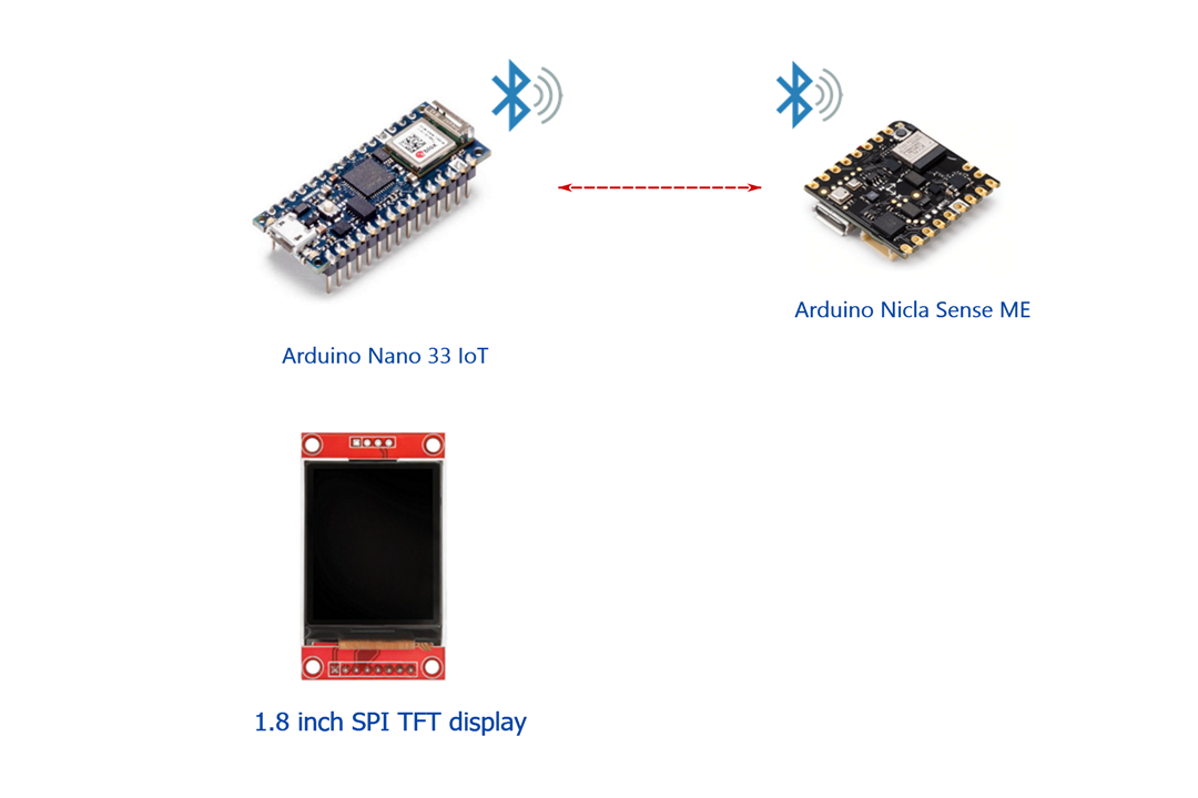
It is a simple remote Air Quality monitor with an Arduino Nicla Sense ME board as a sensor and an Arduino Nano 33 IoT as a monitoring system.
A common problem with portable air quality sensors is that the sensors are too close to the person observing them, which adds noise to the readings with their breathing. In this project we solve the problem by means of a remote monitor that communicates via Bluetooth with the distant sensor.

System Description
The system is made up of a Nicla Sense ME board that will act as a remote sensor and an Arduino Nano 33 IoT board and a color TFT LCD display that will allow us to view the data in real time.
The communication between the two subsystems is carried out through Bluetooth Low Energy (BLE) communication.
The Arduino Nicla Sense ME board will run the "App" firmware from the Arduino_BHY2 library.
The Arduino_BHY2 library provides the APIs for Nicla Sense ME board to make a Device Firmware Update or configure/read BHY sensors. All these operations can be done either via Eslov or BLE. We will use communication via bluetooth low energy BLE.
To visualize the data in real time we will use a TFT ST7735 display. It is a 1.8″ display with a resolution of 128 × 160 pixels and can display a wide range of colors with its 18 bits. The display uses the SPI protocol for communication and has its own pixel addressable frame buffer and only needs 4 I/O pins. It's a slow display, so we'll have to use display update techniques that minimize flickering, only re-drawing small sections of the display.
To complement the display, it also comes with an SD card slot that we will use to store historical data from our sensor.
The Arduino Nicla Sense ME has a BME688 gas sensor. The MBE688 can also measure pressure, humidity and temperature it can detect Volatile Organic Compounds (VCOs), volatile sulfur compounds (VSCs) and other gases such as carbon monoxide and hydrogen in the part per billion (ppb) range. This sensor will allow us to make measurements of air quality.

IAQ Index

User Interface
Air Quality Monitor User Interface
The monitor presents the information using three different screen layouts.
With the buttons you can navigate through the different screens and control the brightness of the display LED.
IAQ Gauge Layout
In this layout, indoor air quality information is presented as an IAQ gauge. Adding information on the temperature and humidity detected by the sensor.
At the top of the display there is an indicator of the accuracy in the measurements that can vary from 0 to 3 and is presented as 4 boxes that may or may not be full.
The accuracy status is equal to zero during the power on stabilization times of the sensor and is equal to 3 when the sensor achieves best performance.
In addition, the current time is displayed with hours and minutes. The time is updated by NTP using the WIFi connection of the Arduino Nano 33 IoT

Values Layout
In this layout, the information is displayed in a single column showing the IAQ, the temperature and the relative humidity obtained from the remote sensor.
Again at the top of the display there is an indicator of the accuracy and the current time.

Historical graphs
On this screen you can view historical data from past and current days in graphic form.
The monitor stores historical data on the SD card.
The date of the plotted data is shown at the top.

Bill of Material:
| Product Name | Manufacturer | Quantity | |
|---|---|---|---|
| Arduino Nano 33 IOT | ARDUINO | 1 | Buy Now |
| Arduino Nicla Sense ME | ARDUINO | 1 | Buy Now |
| 1.8" SPI TFT display 128 x 160 pixels | AZ-DELIVERY | 1 | |
| Hole Grid Board PCB | AZ-DELIVERY | 1 | |
| Hex Threaded Spacer + nuts | DURATOOL | 4 | |
|
Tactile Switch, D6, Top Actuated, Through Hole, Round Button |
4 | ||
|
Mini Storage Bins with Lids |
1 | ||
|
SD card 2GB + Adapter |
|||
|
PCB Receptacle, Board-to-Board, 2.54 mm, 1 Rows, Through Hole Mount, 2212S |
MULTICOMP PRO | 4 | |
|
JST Connectors, male and female |
The remote monitor
Schematics


Construction
The monitor has been built inside a small standard transparent plastic box. Look for Mini Storage Bins with Lids.
There is enough space to house a 9v battery that allows us to directly power the IAQ monitor.
Although the original design was made to use a stripboard, in the end it was decided on this other type of board to be able to secure the headers on both sides of the board.


Firmware
Setting the development environment for the Nicla Sense ME
We will use the Arduino IDE 2.0. If you haven't done it yet download and install the Arduino IDE 2.0
Downloading the Arduino IDE 2.0 is done through the Arduino Software page.
Installing the Nicla Core Support
Open the Arduino IDE 2.0 and navigate to Boards Manager then search for Nicla.
Select The Arduino Mbed OS Nicla Boards by Arduino latest version and install.
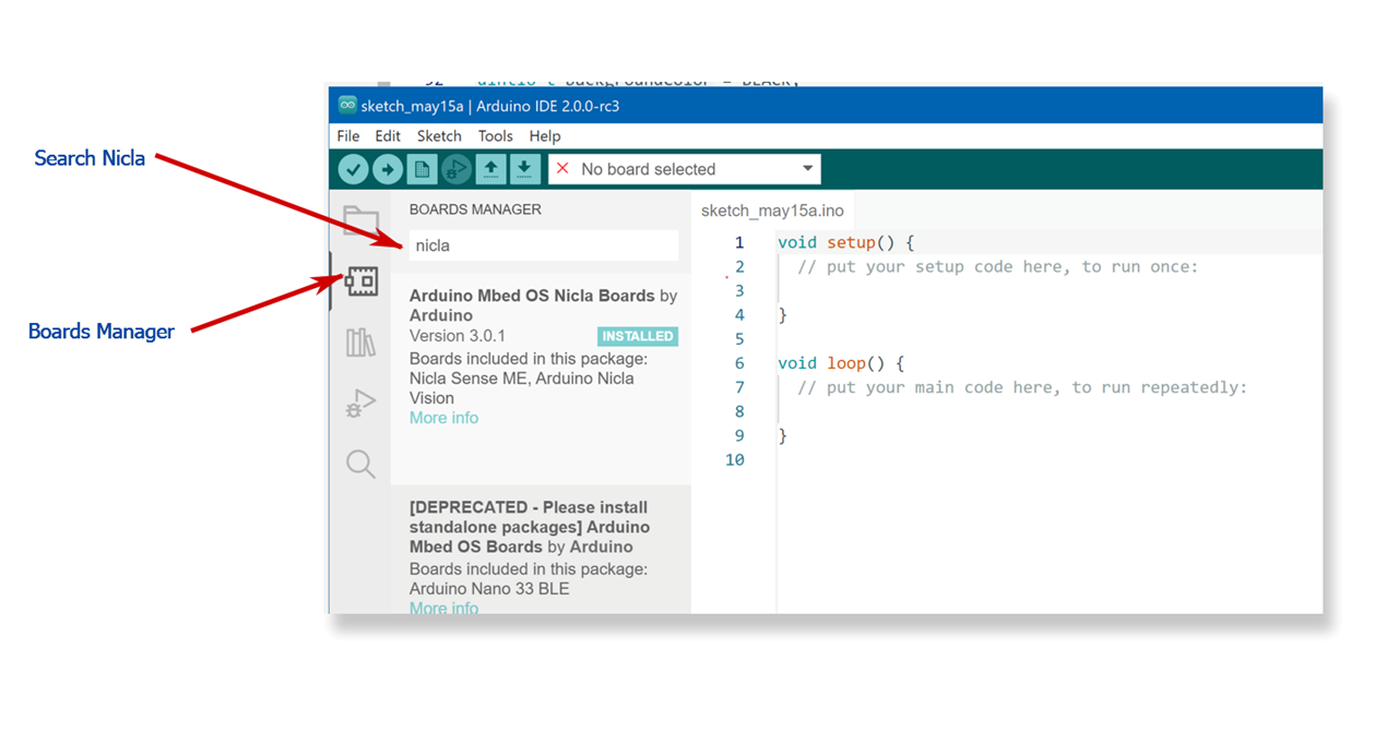
Then connect your Nicla Sense Board to your computer and select it

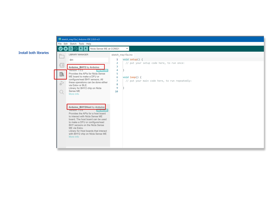
Installing BHY2 libraries
Now we need to install the BHY2 libraries we are going to use both the Arduino_BHY2 for the Arduino Nicla Sense ME and the Arduino_BHY2Host for the Arduino Nano 33 IoT.
Go to the Library Manager and install both libraries. You can search for BHY2.
Installing or updating Arduino BLE
We will use BLE for communication between the two boards. If you do not have the Arduino BLE library installed or updated, it is time to do so.
Again, from the Library Manager search for BLE
Note: For Arduino Nano 33 IoT boards, it requires the NINA module to be running Arduino NINA-W102 firmware v1.2.0 or later.
https://www.arduino.cc/reference/en/libraries/arduinoble/

Updating bhi firmware
Use Arduino_BHY2/examples/BHYFirmwareUpdate/ upload the BHYFirmwareUpdate.ino sketch
Boot status: 11


Boot status: 13

Interrupt ctrl: 0

Interface ctrl: 0
[META EVENT WAKE UP] Firmware initialized. Firmware version 5978
[META EVENT] Firmware initialized. Firmware version 5978

Present sensors:
1 - Accelerometer passthrough
3 - Acceler

Boot status: 11


Boot status: 13

Interrupt ctrl: 0

Interface ctrl: 0
[META EVENT WAKE UP] Firmware initialized. Firmware version 5978
[META EVENT] Firmware initialized. Firmware version 5978

Present sensors:
1 - Accelerometer passthrough
3 - Accelerometer uncalibrated
4 - Accelerometer corrected
5 - Accelerometer offset
6 - Accelerometer corrected wake up
7 - Accelerometer uncalibrated wake up
10 - Gyroscope passthrough
12 - Gyroscope uncalibrated
13 - Gyroscope corrected
14 - Gyroscope offset
15 - Gyroscope wake up
16 - Gyroscope uncalibrated wake up
19 - Magnetometer passthrough
21 - Magnetometer uncalibrated
22 - Magnetometer corrected
23 - Magnetometer offset
24 - Magnetometer wake up
25 - Magnetometer uncalibrated wake up
28 - Gravity vector
29 - Gravity vector wake up
31 - Linear acceleration
32 - Linear acceleration wake up
34 - Rotation vector
35 - Rotation vector wake up
37 - Game rotation vector
38 - Game rotation vector wake up
40 - Geo-magnetic rotation vector
41 - Geo-magnetic rotation vector wake up
43 - Orientation
44 - Orientation wake up
48 - Tilt detector
50 - Step detector
52 - Step counter
53 - Step counter wake up
55 - Significant motion
57 - Wake gesture
59 - Glance gesture
61 - Pickup gesture
63 - Activity recognition
67 - Wrist tilt gesture
69 - Device orientation
70 - Device orientation wake up
75 - Stationary detect
77 - Motion detect
94 - Step detector wake up
112 - Undefined sensor ID
115 - Undefined sensor ID
128 - Temperature
129 - Barometer
130 - Humidity
131 - Gas
132 - Temperature wake up
133 - Barometer wake up
134 - Humidity wake up
135 - Gas wake up
HCI COMMAND TX -> 01030C00
HCI EVENT RX <- 040E0401030C00
HCI COMMAND TX -> 01011000
HCI EVENT RX <- 040E0C01011000090323095F000323
HCI COMMAND TX -> 01010C08FFFFFFFFFFFFFF3F
HCI EVENT RX <- 040E0401010C00
HCI COMMAND TX -> 01022000
HCI EVENT RX <- 040E0701022000000104
HCI COMMAND TX -> 010A200100
HCI EVENT RX <- 040E04010A2000
HCI COMMAND TX -> 0106200FA000A0000000000000000000000700
HCI EVENT RX <- 040E0401062000
HCI COMMAND TX -> 01082020150201061106020012AC4202C1ADEB11AA34BBE3C23400000000000000000000
HCI EVENT RX <- 040E0401082000
HCI COMMAND TX -> 010920200706094E49434C41000000000000000000000000000000000000000000000000
HCI EVENT RX <- 040E0401092000
HCI COMMAND TX -> 010A200101
HCI EVENT RX <- 040E04010A2000
Eslov int pin: 19
Upload BHY2 App to your Arduino Nicla Sense Board.
We will install the BHY2 App on the Nicla Sense Board. This sketch allows you to control nicla from an external device acting as a host.
We will use the Arduino Nano 33 IoT as a host sending stimuli through BLE.
Navigate to File/Examples/Arduino_BHY2/App

Also you will need to increment packet length for App firmware. Look for sensors/SensorTypes.h header file and change
#define SENSOR_LONG_DATA_FIXED_LENGTH (18)
to #define SENSOR_LONG_DATA_FIXED_LENGTH (30)
It is a very simple sketch, initially we will set DEBUG to true to be able to see through the serial port how it reacts to BLE calls.
#include "Arduino.h"
#include "Arduino_BHY2.h"

// Set DEBUG to true in order to enable debug print
#define DEBUG true

void setup()
{
#if DEBUG
  Serial.begin(115200);
  BHY2.debug(Serial);
#endif

  BHY2.begin();
}

void loop()
{
  // Update and then sleep
  BHY2.update(100);
}
Upload the BHY2 App sketch to your Nicla Sense ME
It's quite a long compile time compared to when you compile for the Arduino UNO
Info : CMSIS-DAP: SWD  Supported
Info : CMSIS-DAP: FW Version = v1.0
Info : CMSIS-DAP: Serial# = A7B3C296
Info : CMSIS-DAP: Interface Initialised (SWD)
Info : SWCLK/TCK = 1 SWDIO/TMS = 1 TDI = 0 TDO = 0 nTRST = 0 nRESET = 1
Info : CMSIS-DAP: Interface ready
Info : clock speed 1000 kHz
Info : SWD DPIDR 0x2ba01477
Info : nrf52.cpu: hardware has 6 breakpoints, 4 watchpoints
Info : starting gdb server for nrf52.cpu on 3333
Info : Listening on port 3333 for gdb connections
target halted due to debug-request, current mode: Thread
xPSR: 0x01000000 pc: 0x00006dc4 msp: 0x20010000
target halted due to debug-request, current mode: Thread
xPSR: 0x01000000 pc: 0x00006dc4 msp: 0x20010000
** Programming Started **
Info : nRF52832-CIAA(build code: E1) 512kB Flash, 64kB RAM
Warn : Adding extra erase range, 0x00055b78 .. 0x00055fff
** Programming Finished **
shutdown command invoked

--------------------------
upload complete.
If we have activated the DEBUG, adjusting the speed of the serial port monitor to 115200 baud we will obtain the following trace.
Boot status: 11


Boot status: 13

Interrupt ctrl: 0

Interface ctrl: 0
[META EVENT WAKE UP] Firmware initialized. Firmware version 5978
[META EVENT] Firmware initialized. Firmware version 5978

Present sensors:
1 - Accelerometer passthrough
3 - Acceler

Boot status: 11


Boot status: 13

Interrupt ctrl: 0

Interface ctrl: 0
[META EVENT WAKE UP] Firmware initialized. Firmware version 5978
[META EVENT] Firmware initialized. Firmware version 5978

Present sensors:
1 - Accelerometer passthrough
3 - Accelerometer uncalibrated
4 - Accelerometer corrected
5 - Accelerometer offset
6 - Accelerometer corrected wake up
7 - Accelerometer uncalibrated wake up
10 - Gyroscope passthrough
12 - Gyroscope uncalibrated
13 - Gyroscope corrected
14 - Gyroscope offset
15 - Gyroscope wake up
16 - Gyroscope uncalibrated wake up
19 - Magnetometer passthrough
21 - Magnetometer uncalibrated
22 - Magnetometer corrected
23 - Magnetometer offset
24 - Magnetometer wake up
25 - Magnetometer uncalibrated wake up
28 - Gravity vector
29 - Gravity vector wake up
31 - Linear acceleration
32 - Linear acceleration wake up
34 - Rotation vector
35 - Rotation vector wake up
37 - Game rotation vector
38 - Game rotation vector wake up
40 - Geo-magnetic rotation vector
41 - Geo-magnetic rotation vector wake up
43 - Orientation
44 - Orientation wake up
48 - Tilt detector
50 - Step detector
52 - Step counter
53 - Step counter wake up
55 - Significant motion
57 - Wake gesture
59 - Glance gesture
61 - Pickup gesture
63 - Activity recognition
67 - Wrist tilt gesture
69 - Device orientation
70 - Device orientation wake up
75 - Stationary detect
77 - Motion detect
94 - Step detector wake up
128 - Temperature
129 - Barometer
130 - Humidity
131 - Gas
132 - Temperature wake up
133 - Barometer wake up
134 - Humidity wake up
135 - Gas wake up
171 - Custom sensor ID
HCI COMMAND TX -> 01030C00
HCI EVENT RX <- 040E0401030C00
HCI COMMAND TX -> 01011000
HCI EVENT RX <- 040E0C01011000090323095F000323
HCI COMMAND TX -> 01010C08FFFFFFFFFFFFFF3F
HCI EVENT RX <- 040E0401010C00
HCI COMMAND TX -> 01022000
HCI EVENT RX <- 040E0701022000000104
HCI COMMAND TX -> 010A200100
HCI EVENT RX <- 040E04010A2000
HCI COMMAND TX -> 0106200FA000A0000000000000000000000700
HCI EVENT RX <- 040E0401062000
HCI COMMAND TX -> 01082020150201061106020012AC4202C1ADEB11AA34BBE3C23400000000000000000000
HCI EVENT RX <- 040E0401082000
HCI COMMAND TX -> 010920200706094E49434C41000000000000000000000000000000000000000000000000
HCI EVENT RX <- 040E0401092000
HCI COMMAND TX -> 010A200101
HCI EVENT RX <- 040E04010A2000
Eslov int pin: 19
HCI EVENT RX <- 043E13010000000101F5D37481CE7324000000F40101
HCI ACLDATA RX <- 0200200B0007000400100100FFFF0028
HCI ACLDATA TX -> 02000012000E0004001106010005000018060009000118
HCI EVENT RX <- 0413050100000100
HCI ACLDATA RX <- 0200200B0007000400100A00FFFF0028
HCI ACLDATA TX -> 0200001A001600040011140A000E00020012AC4202C1ADEB11AA34B8E3C234
HCI ACLDATA RX <- 0200200B0007000400100F00FFFF0028
HCI ACLDATA TX -> 0200001A001600040011140F001700020012AC4202C1ADEB11AA34BBE3C234
HCI EVENT RX <- 0413050100000100
HCI ACLDATA RX <- 0200200B0007000400101800FFFF0028
HCI ACLDATA TX -> 020000090005000400011018000A
HCI EVENT RX <- 0413050100000100
HCI EVENT RX <- 043E0A0300000006000000F401
HCI ACLDATA RX <- 0200200B000700040008010005000228
HCI ACLDATA TX -> 020000090005000400010801000A
HCI EVENT RX <- 0413050100000100
HCI ACLDATA RX <- 0200200B000700040008010005000328
HCI ACLDATA TX -> 02000014001000040009070200020300002A0400020500012A
HCI EVENT RX <- 0413050100000100
HCI ACLDATA RX <- 0200200B000700040008050005000328
HCI ACLDATA TX -> 020000090005000400010805000A
HCI EVENT RX <- 0413050100000100
HCI ACLDATA RX <- 0200200B000700040008060009000228
HCI ACLDATA TX -> 020000090005000400010806000A
HCI EVENT RX <- 0413050100000100
HCI ACLDATA RX <- 0200200B000700040008060009000328
HCI ACLDATA TX -> 0200000D000900040009070700200800052A
HCI EVENT RX <- 0413050100000100
HCI ACLDATA RX <- 0200200B000700040008080009000328
HCI ACLDATA TX -> 020000090005000400010808000A
HCI EVENT RX <- 0413050100000100
HCI ACLDATA RX <- 0200200900050004000409000900
HCI ACLDATA TX -> 0200000A0006000400050109000229
HCI EVENT RX <- 0413050100000100
HCI ACLDATA RX <- 0200200B0007000400080A000E000228
HCI ACLDATA TX -> 02000009000500040001080A000A
HCI EVENT RX <- 0413050100000100
HCI ACLDATA RX <- 0200200B0007000400080A000E000328
HCI ACLDATA TX -> 0200001B001700040009150B00080C00020012AC4202C1ADEB11AA34B9E3C234
HCI EVENT RX <- 0413050100000100
HCI ACLDATA RX <- 0200200B0007000400080C000E000328
HCI ACLDATA TX -> 0200001B001700040009150D00080E00020012AC4202C1ADEB11AA34BAE3C234
HCI EVENT RX <- 0413050100000100
HCI ACLDATA RX <- 0200200B0007000400080E000E000328
HCI ACLDATA TX -> 02000009000500040001080E000A
HCI EVENT RX <- 0413050100000100
HCI ACLDATA RX <- 0200200B0007000400080F0017000228
HCI ACLDATA TX -> 02000009000500040001080F000A
HCI EVENT RX <- 0413050100000100
HCI ACLDATA RX <- 0200200B0007000400080F0017000328
HCI ACLDATA TX -> 0200001B001700040009151000081100020012AC4202C1ADEB11AA34BDE3C234
HCI EVENT RX <- 0413050100000100
HCI ACLDATA RX <- 0200200B000700040008110017000328
HCI ACLDATA TX -> 0200001B001700040009151200121300020012AC4202C1ADEB11AA34BCE3C234
HCI EVENT RX <- 0413050100000100
HCI ACLDATA RX <- 0200200B000700040008130017000328
HCI ACLDATA TX -> 0200001B001700040009151500121600020012AC4202C1ADEB11AA34BEE3C234
HCI EVENT RX <- 0413050100000100
HCI ACLDATA RX <- 0200200B000700040008160017000328
HCI ACLDATA TX -> 020000090005000400010816000A
HCI EVENT RX <- 0413050100000100
HCI ACLDATA RX <- 0200200900050004000414001400
HCI ACLDATA TX -> 0200000A0006000400050114000229
HCI EVENT RX <- 0413050100000100
HCI ACLDATA RX <- 0200200900050004000417001700
HCI ACLDATA TX -> 0200000A0006000400050117000229
HCI EVENT RX <- 0413050100000100
HCI EVENT RX <- 0413050100000100
HCI EVENT RX <- 043E0A0300000024000000F401
HCI ACLDATA RX <- 0200200900050004001217000100
HCI ACLDATA TX -> 02000005000100040013
HCI EVENT RX <- 0413050100000100
HCI ACLDATA RX <- 0200200700030004000A1700
HCI ACLDATA TX -> 0200000700030004000B0100
HCI EVENT RX <- 0413050100000100
HCI ACLDATA RX <- 0200200900050004001214000100
HCI ACLDATA TX -> 02000005000100040013
HCI EVENT RX <- 0413050100000100
HCI ACLDATA RX <- 0200200700030004000A1300
HCI ACLDATA TX -> 020000090005000400010A130007
HCI EVENT RX <- 0413050100000100
We already have our remote sensor ready. Let's connect from an Android phone using the Nordic Semiconductor nRF Connect App


Remote monitor firmware
You can download or review the firmware source code for the Arduino Nano 33 IoT in the following repository on Github.
https://github.com/javagoza/Remote-IAQ-Monitor
Libraries
You will need to install the following Libraries
- adafruit/Adafruit-ST7735-Library: library for the Adafruit 1.8" SPI display
- adafruit/Adafruit-GFX-Library: Adafruit GFX graphics core library
- arduino-libraries/RTCZero: RTC Library for SAMD21 based boards
- arduino-libraries/NTPClient: Connect to a NTP server (github.com)
The code makes use of a modified library for simulating 7-segment displays on TFT screens that I recently created for an Arduino UNO chess clock project.
The modified library is included in the repository.
How does it work?
When starting the monitor, it connects to the Internet using the WiFi of the wifinina module and retrieves the current time through an NTP client that updates the time from the RTCZero library.
Then the BHYHost module starts indicating that it has to search for a NICLA module by BLE connection.
BHY2Host.begin(false, NICLA_VIA_BLE)
When the connection to the NICLA module, that is running the Bosch App firmware, is established, the monitor registers as a consumer of BSEC packets
SensorBSEC co2Sensor(SENSOR_ID_BSEC);
... co2Sensor.begin();
SENSOR_ID_BSEC is the new data format for the BSEC data. You need to update the Nicla bhi firmware to the last version. See section: ."Updating bhi firmware"
Also you will need to increment packet length for App firmware and BHY2Host Library
sensors/SensorTypes.h
Change: #define SENSOR_LONG_DATA_FIXED_LENGTH (18) to #define SENSOR_LONG_DATA_FIXED_LENGTH (30) in both libraries
Historical data format
Historical data is stored on the SD card. One CSV file per day. The file name has the following pattern: YYMMDD.txt
  // if the file opened okay, write to it:
  if (dataLogggerFile) {
    if (isNewFile) {
      // write header
      dataLogggerFile.println( F("'time','IAQ','ACCURACY','TEMP','HUMIDITY','CO2EQ','VOCEQ','IAQS'"));
    }
    dataLogggerFile.print( logTime);
    dataLogggerFile.print(",");
    dataLogggerFile.print( co2Sensor.iaq());
    dataLogggerFile.print(",");
    dataLogggerFile.print( co2Sensor.accuracy());
    dataLogggerFile.print(",");
    dataLogggerFile.print( co2Sensor.comp_t());
    dataLogggerFile.print(",");
    dataLogggerFile.print( co2Sensor.comp_h());
    dataLogggerFile.print(",");
    dataLogggerFile.print( co2Sensor.co2_eq());
    dataLogggerFile.print(",");
    dataLogggerFile.print( co2Sensor.b_voc_eq());
    dataLogggerFile.print(",");
    dataLogggerFile.print( co2Sensor.iaq_s());
    dataLogggerFile.println("");
    // close the file:
    dataLogggerFile.close();
  }
References
Source code of the project and other related projects that I have previously built:
- Source Code: javagoza/Remote-IAQ-Monitor (github.com)
- Venttracker Environmental Monitor Version 2
- Venttracker Environmental Monitor Version 1
- Arduino UNO Chess Clock TFT LCD Virtual Clock Display Library
- Arduino UNO TFT LCD Chess Clock with full time controls
Arduino and Bosch Sensortec Documentation
- Arduino Nicla Sense ME documentation
- Arduino Nano 33 IoT documentation
- Bosch Sensortec: Arduino Nicla Sense ME
- Nicla Sense ME Firmware
- Gas sensor BME688 | Bosch Sensortec (bosch-sensortec.com)
Next steps

Conclusion
A few weeks ago I made a simple remote CO2 monitor project using an Arduino Nano 33 BLE and the Arduino Nicla Sense ME board . During the following weeks I was using it in the office and I realized things that were missing, such as multiple screens, navigation buttons, reset button, historical data storage, automatic update of the time from the internet, graphing of the data, reduce flickering, brightness control of the LED of the display...
First attempt with and Arduino BLE as monitor board, BLE connection but no WiFi:
I have introduced all those improvements to that first project and surely it will not stop at this and I will improve it even more.
Thanks for reading!
Top Comments