


 | Enter Your Electronics & Design Project for a chance to win a $200 shopping cart! Back to homepage | Project14 Home |
| Monthly Themes | ||
| Monthly Theme Poll |
Links to the previous parts
Synth Circuit
As I finished the prototype of the NE555-based synth circuit (one module), including information I catch on the Internet and some knowledge from previous experience, in the end, I designed a circuit that – still in the building phase – should integrate three synth modules and accepting the radio input. The prototypal circuit will be done on a prototyping PCB board so I drafted it with Fritzing; a final PCB for a small production will be done with Altium at the end of the creation of this prototype.
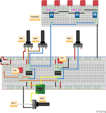
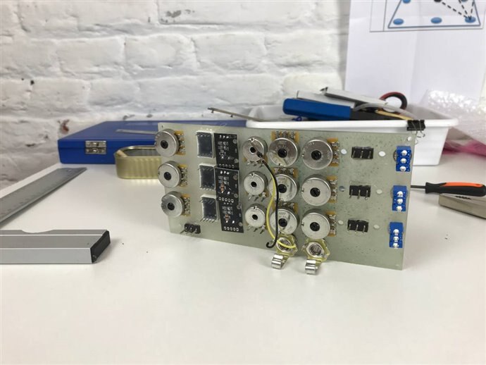
The above image shows the wiring of a single module; it includes (on the top side) the five different capacitors that can be selected to change the frequency range of the oscillators. Then (see the image below) I joined the three modules, each one with its independent output volume control, mixed to a single output with a master volume control.
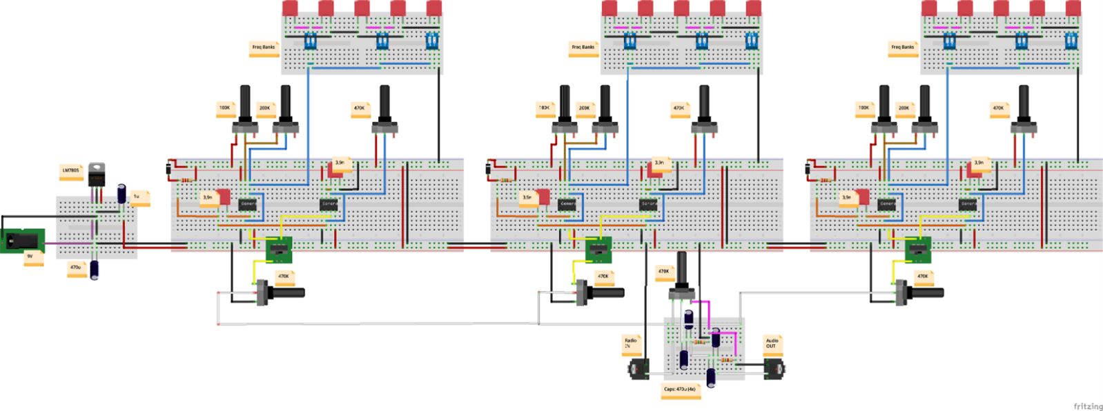
To keep the "vintage-style" also the power supply is provided by a simple LM7805.
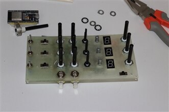
Digital Connection
I decided that for a question of usability the control potentiometers should remain manual controlled. What instead should be under the control of the microcontroller, included in the same box of the synth circuitry, is the capacitors switching; to do this, I will use a digital encoder for every module associated to a single-digit 7-segments LED to change easily the corresponding capacitor, from 1 to 5 (from lower to higher frequency). To manage the three displays I will use three daisy-chained shift registers 14HC595 to save GIPIO pins. The image below shows the kind of circuit I will use for the display part (the wiring of the 7-segments LED is shown only for the first one, should be the same for the other three).
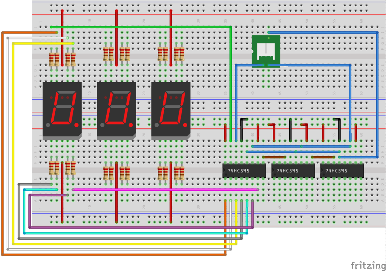
About the rotary encoder and the display please read the not below
Note on the Display and Rotary Encoders (an exploring alternative)
Until now the design of the synth modules is not limited to only three inputs. As a matter of fact, more other modules can be added to generate more complex sounds. Adopting the solution described above instead, the capacitors switching method using the three-chained displays may be a limitation. I am also experimenting with a different possibility, using an inexpensive Arduino Nano for each capacitors' bank switch. Using this method, the system will still work regardless of the number of synth modules that are used.
In case I decide to adopt this Arduino Nano alternative, I will use a Nano for every display associated with the corresponding rotary encoder. The physical switching of the capacitors is actuated by an analog switch IC. This approach (maybe the one I will choose for the final solution is possible as the selection of the capacitor bank is part of the hardware control of the synth module with no impact on the logic of the modules chain that is controlled by the main microcontroller.
The Main Microcontroller
For the main microcontroller, I have decided to use an ESP32 MCU, the ideal and cheapest solution for the tasks it should do. The roles of the ESP32 are the following:
- Can be programmed to control the Radio input range of frequencies
- Can enable/disable the output signal Controlled by the user and the Raspberry Pi
- Exposes a series of commands through Reful API calls
- Maybe something else should be implemented
To see how the radio frequencies are controlled will be described in the next point.
Synth Box Control Panel
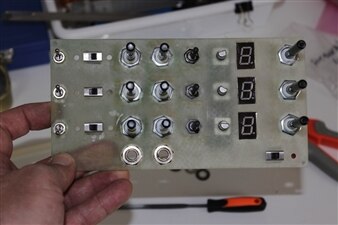
To proceed with the building of this hacking project it is necessary to start designing and making the control panel else become difficult to implement the circuit part.
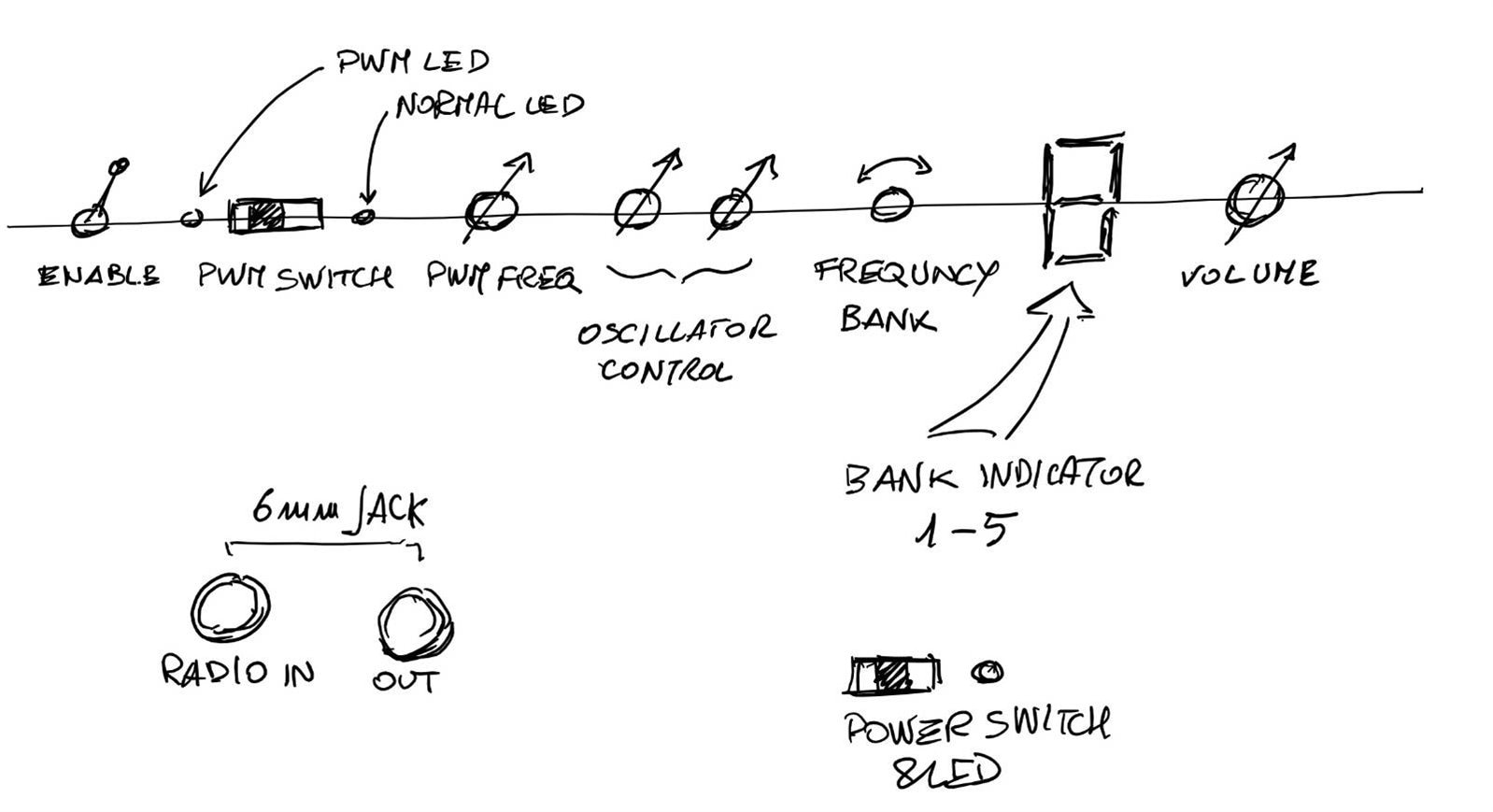
The sketch above shows the controls of a single row of the panel; the actual design should include three identical rows, one for every synth module. From left to right:
- Enable/Disable Switch It is associated with a digital input of the ESP32 that can enable or disable the corresponding module switching the two pins #4 of the NE555 (reset) to the ground.
- PWM Switch changes the kind of output waveform depending on the NE555 is selected. It is directly connected to the output of the module and is user-controlled.
- Control potentiometers to control respectively the PWM frequency and the wave shape of the other NE555 oscillator.
- Frequency bank and 7-segments LEDs Display as described above it is the digital-to-analog switch to change the sounds range depending on the selected capacitor.
- Volume Potentiometer is the module output volume. A master volume controls the final output that will be on the front side of the box.
Note that the Radio In plug is the fourth external module connected to the radio.
The Design and Making-of the Control Panel
The image below shows the rendering of the controller designed with Fusion360 and the 3D printing with the Elegoo Saturn with transparent resin.
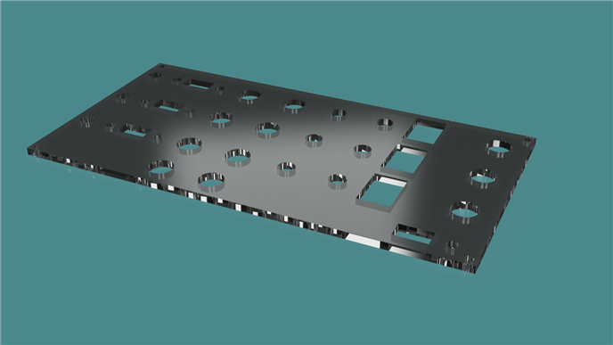
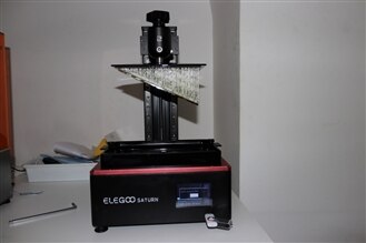
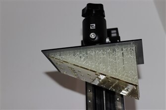
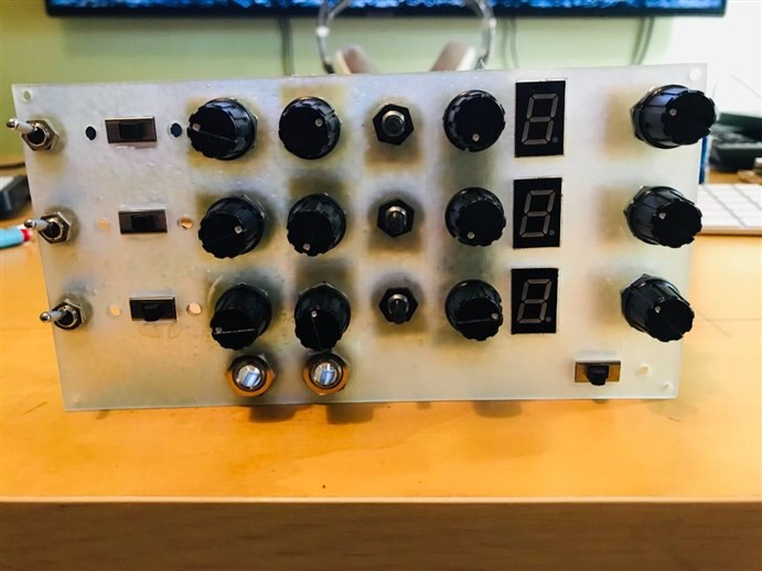
Above: rendering and 3D printing of the control panel with transparent resin.
After the assembly, the panel is ready to be connected to the circuits.
Hacking the Radio
Also, vintage radio needs some changes and "upgrades": the two important aspects to change are the audio output and the tuning control.
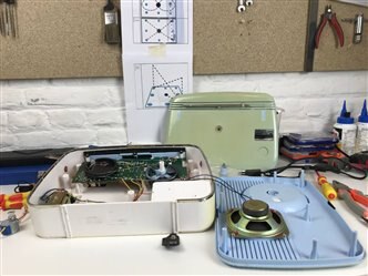
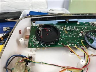
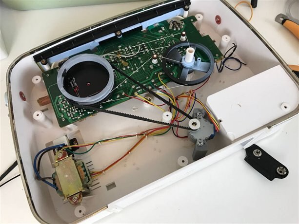
The above image shows the front-side internal parts of the device. As I have excluded the built-in amplifier section (radio-out will be the output of the pre-amplified earphone), I have removed the speaker freeing the needed space inside for the solution I figured out. I appreciated the tuning mechanism – luckily, the wires are still in perfect conditions – almost big, relatively easy to modify.
To understand what I have done we should think about the use of the output: sampling the radio output together with the generated sounds along with one of the frequencies range (FM-AM-LW). Better if the tuning is continuously variated in a selected range during the sampling (or just the sound generation). To do so, I decided to automate the tuning mechanism instead of keeping the manual tune, that after the changes will be driven by the radio itself. To do this task I adopted a geared stepper motor controlled by the microcontroller.
Mechanics Design
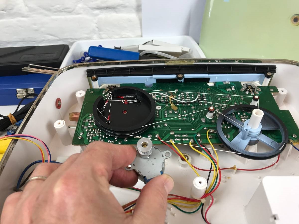
To move the tuning potentiometer the stepper motor should be fixed to the right height and a pulley should be added on top of the already existing wire driving mechanism (the left black pulley in the above image). I want to keep fully functional the manual tuning pulley (the right one in the above image). As shown in the rendering below I designed the pulley of the same diameter of the tuning pulley and a couple of supports for the stepper motor (see the images below).
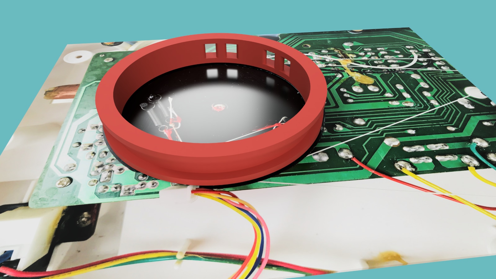
Above: simulated rendering of the driven pulley to be placed on top of the tuning pulley.
Below: rendering of the stepper support and the 3D printed components.
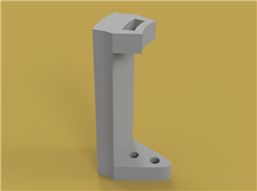
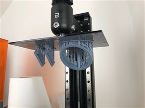
This part has been assembled without difficulty and now is ready for testing. Note that the pulley glued over the tuning wheel should only cover a 180 Deg rotation. This made it possible to add a tooths belt locked on two sides after positioning the stepper motor. The image below shows the final assembly.
Top Comments
-

Jan Cumps
-
Cancel
-
Vote Up
+2
Vote Down
-
-
Sign in to reply
-
More
-
Cancel
-

balearicdynamics
in reply to Jan Cumps
-
Cancel
-
Vote Up
+2
Vote Down
-
-
Sign in to reply
-
More
-
Cancel
Comment-

balearicdynamics
in reply to Jan Cumps
-
Cancel
-
Vote Up
+2
Vote Down
-
-
Sign in to reply
-
More
-
Cancel
Children