


Hello everyone. I welcome you to my blog describing my project as part of Project14 World in Motion competition.
Do you remember Duratool Storage Cabinet Giveaway? I was one of five lucky winners and as part of World in Motion competition I decided to upgrade my storage cabinet box by adding ethernet connected device which will automatically open boxes containing searched parts.

See it in the action!
Sample Sponsors
At the beginning I would like to thank vendors who send me free samples of their parts which I used in this project.
Thank Renesas for sending me EK-RA6M4 development kit with RA6M4 microcontroller featuring 200MHz ARM Cortex-M33 microcontroller with ethernet onboard connectivity. This board I used for controlling whole device.

Thank Maxim Integrated (now ADI) for sending me free samples of MAX16935 DC/DC stepdown voltage regulator and MAX5715 Digital to Analog converter which is used for generating voltage used for current limiting motor current.

Thank Samtec for sending me free samples of ESQ-106-34-L-S-LL and ESQ-108-34-L-S-LL elevated sockets strips which I used for patching connection of my shield.

Implementation overview
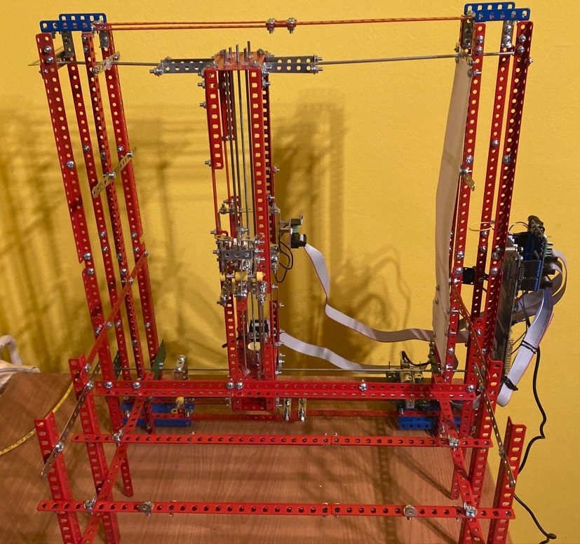
This project is build using mechanical building set, two motors, one solenoid, Renesas EK-RA6M4 devboard featuring Renesas microcontroller with Ethernet connectivity, two ST VL53L0X time of flight sensors, custom Arduino shield designed by me, FreeRTOS based firmware enabling controlling device over ethernet and simple component database PC application allowing to automatically open box containing searched part. Device operates in a way that move in horizontal and vertical direction using electromotors and use solenoid for pushing storage cabinet from the back. This cause storage box to open.
Mechanical construction
The most complex part of this project is its mechanical construction. It is built from building set, which is in Czechia known under Merkur brand, but project can be built with other similar building sets like British Meccano or you can also try similar building set from China available under multiple brands. Note that all build sets have different dimensions. You will most probably need to adjust sizes if you decide to recreate it on your own. I have not tried other building sets. Czech building set Merkur is sized with exactly 1 cm (10 mm) pitch between points, and it is designed for use with M3.5 screws and nuts but I used M4 instead and in few cases I used M3. Constructions contains over 200 M4x10 screws and nuts and over 50 M3x6 screws.
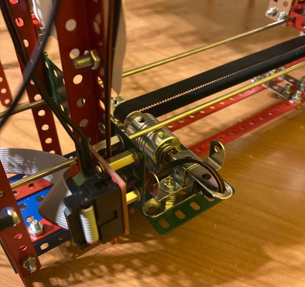
Movement in horizontal direction is done using electromotor with rubber gear belt attached to it’s shaft. Module is hold straight by three 3mm stainless steal rods. Size of each rod is 500 mm (50 cm). I did not find exact sizes of rods in Czech stores, so I had to order 1 m rods and cut them. (This means that I also had to order a vice and a hacksaw, since I never cut rods in home before).
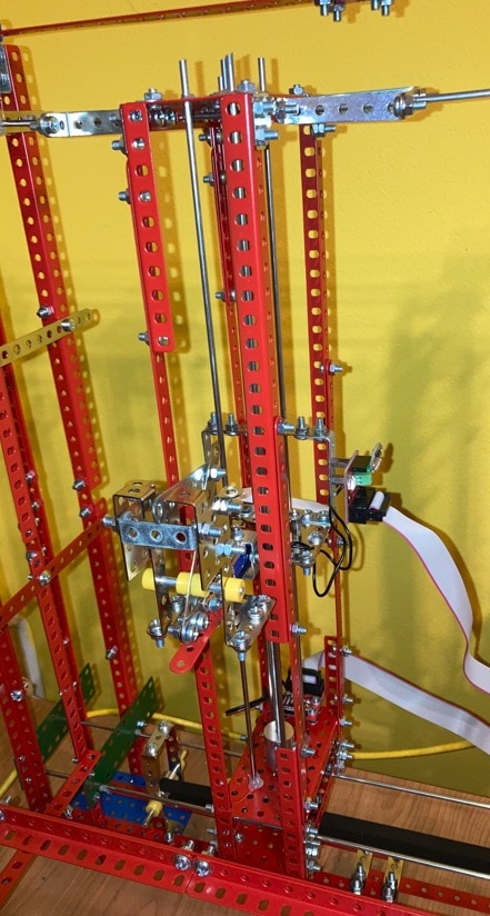
Movement in vertical direction is done by rotating threaded rod with flange nut. Note that I am not sure if “flange nut” is correct term. I do not know how to name this thing even in my natural language (Czech) but I found it on internet under this name. Flange nut is attached to the building set components and holds construction used for pushing box. For making module fixed it is attached to the vertical construction using four 3mm stainless steel rods. Motor is at the bottom and rotates with threaded rod. Because position of flange nut is fixed, motor motion push it up and reverse motor motion push it down. It is similar concept to concept which is used on some 3D printer. (3D printer was big inspiration to me when building this project).
Motors are very small motors which I found on Aliexpress under N20 name. I originally expected larger motor, but this 12V small motor was powerful enough for this project.
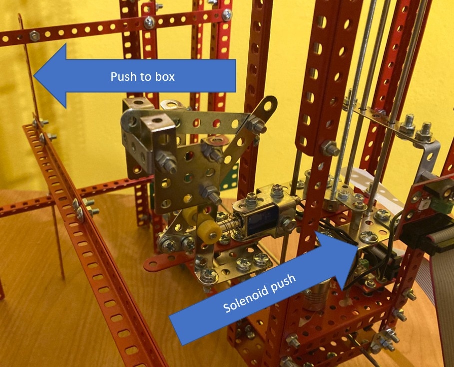
Module for pushing boxes holds solenoid which can push or pull target by 10 mm (1 cm). This is not enough for pushing boxes. For this reason, I made lever which reverse direction of pushing and extends range to approximately 40 mm (4 cm).
Electronics
I guess the most interesting part for Element14 community is of course electronics part. In fact electronics and programming part was much easier than building mechanical construction.
The electronics part can be easily visualized using following block diagram.
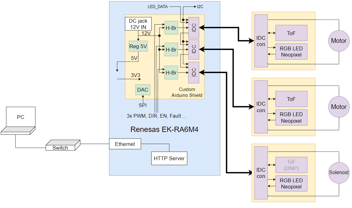
Device is controlled digitally. Main MCU is Renesas RA6M4 on Renesas EK-RA6M4. I chose it because it has Ethernet connectivity and I consider ethernet more suitable and reliable than wi-fi connection for this industrial-like devices. For interfacing motors and other components, I designed my own shield. Shield has pinout adjusted to match Renesas RA6M4 peripherals. It was designed to contain three Maxim Integrated MAX14871 motor drivers. Motors are not directly connected to the board but they are connected to the module which are connected to the shield using 2x7 pin IDC cables.
At block diagram you maybe noticed some crazy arrows regarding voltages. I decided shield to backrower Renesas EK-RA6M4 from my shield. I did this because I need 12V for motors. 12V is provided from power adapter to the shield. Shield has onboard 5V DC/DC regulator. This design allow use only single (12V) supply and do not require you to provide separate 5V supply for EK-RA6M4 board since it is powered from shield. I used MAX16935 as DC/DC regulator. It is the same DC/DC stepdown regulator which I used in my previous Project14 project Digitaly Adjustable Power Supply. 5V created by this regulator is backpowered to the EK-RA6M4. You do not need any USB connection or external 5V supply for operation. 3.3V then is created by onboard LDO which is available on EK-RA6M4 board and fed back to the shield. Shield has 3 amber LEDs for indicating voltages on 12V, 5V and 3.3V nets.
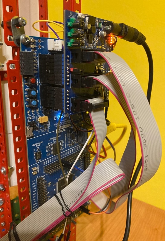
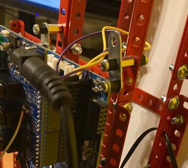
Final device is attached using standoffs to the mechanical construction:
Shield
As I mentioned above for this project, I designed my own Arduino shield. It has three IDC connectors for connecting motor modules, 3 motor drivers, DAC for digital adjustment of current limit of motor drivers and 12 to 5V voltage regulator. Schematic of the shield is shown on following image. It is also available to download as (multipage) PDF at the end of this blog post. As you see It is quite a complex board but still fits the Arduino shield size. Shield utilize all pins (no free pins for other stacked shields).

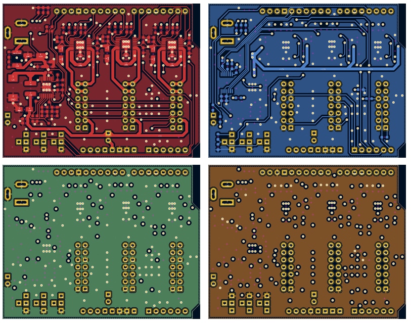
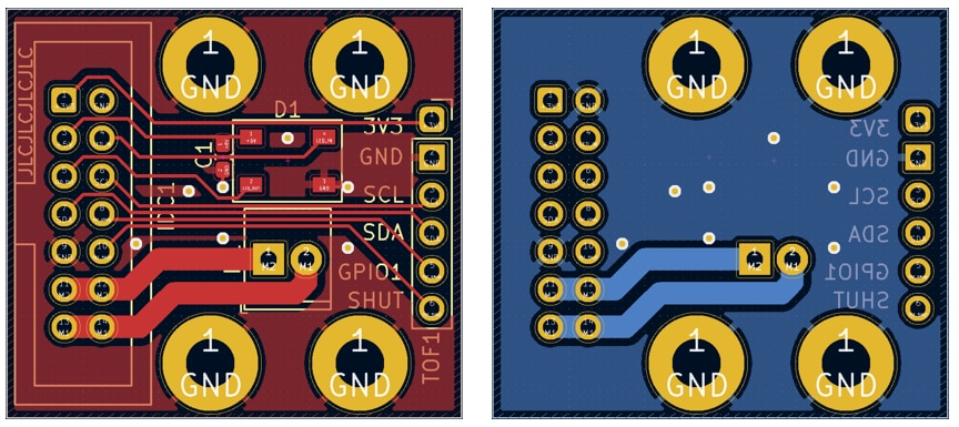
I designed shield as 4 layer PCB. Top and bottom layers are used for signals and inner layers are ground plane and 3.3V plane. 12V and 5V signals I routed on signal layers. Following image shows layers in Kicad (top is red, bottom is blue, inner near top is green and inner near bottom is orange).
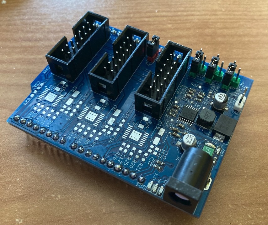
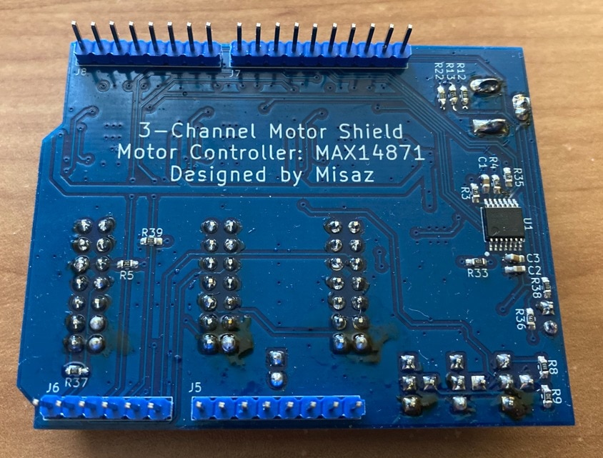
Then I ordered PCB prototypes at JLCPCB and after assembling it looked as follows:
Not Received MAX14871 Motor Driver
I originally designed my shield with MAX14871 motor driver. I tried to order free sample of this chip but for some reason I did not receive it even Maxim confirmed my sample order. Additional issue was that most of the time MAX14871 was sold out at distributors (but in stock at Maxim website), but about two weeks before deadline distributors stocked them. I decided to do not wait for sample order anymore and ordered few pcs of it on Farnell and hoped that I will receive them before weekend, which is virtually deadline for me because school started, and I will be out of home last week. Sadly, it for some reason took over 40 hours before UPS picked up package from Farnell and I did not received package before weekend. It was delivered on Monday but because I am out of home, I have not seen the package yet. I am unable to check it and use them in the project. For this reason, I had to improvise, and I found alternative old dual motor driver module in my unused electronics cabinet. It features L9110S motor driver which is older and worse than MAX14871 and has no current limiting feature but for basic operations can be used. Module which I have is driven differently than MAX14871, so I had to change firmware. MAX14871 is driven by one PWM signal and direction (logical 0 or 1) signal. L9110S is driven by two PWM signals. Because PCB of my shield has footprints only for MAX14871 I had to patch lot of wires from alternative motor driver module to the IDC connectors. Lastly, I need 3 drivers (2 for motors and 1 for solenoid) but my module supported only 2 channels. I resolved this that I used two available channels for driving motor and I switched solenoid by transistor instead of motor driver.
Swapped I2C signals SDA and SCL :(
The biggest design mistake which I did is swapping SCL and SDA wires.
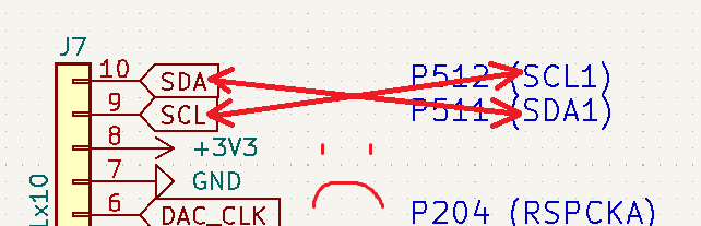
As you can see, I properly wrote comment that RA6M4 pin P512 is SCL and P511 SDA but then for very mysterious reason I swapped labels. I did not noticed this even I at least triple checked it before sending to JLCPCB. The good part is that SDA and SCL wires are at the corner of pinheads. For now, I patched this bug by using elevated socked strips from Samtec and not connecting SDA and SCL wires using this socket strip. They are the same elevated sockets which I used in Blog #12: Long Term Power Consumption Monitoring but now I used them for different reason. Elevated socket strip make space between boards which allowed me to connect wires between boards and properly swap them. Other pins are connected using elevated socket strip directly. Elevated socket strips reliably connect other wires while letting me to swap I2C wires. Patched wires are visible as purple and yellow wires on the photo below:
For future I will resolve this issue differently. In fact swapping SDA and SCL does not affect operation of this shield because there are no onboard I2C peripheral. The only purpose of I2C here is that it is directly connected to the IDC connectors which are later connected to I2C ToF sensors. So, I have two options:
- Correct shield and swap lines here
- Swap lines on ToF board
I will select second option because I want to redesign second board for more reasons (and also I do not want to solder over 50 components on shield again).
Modules
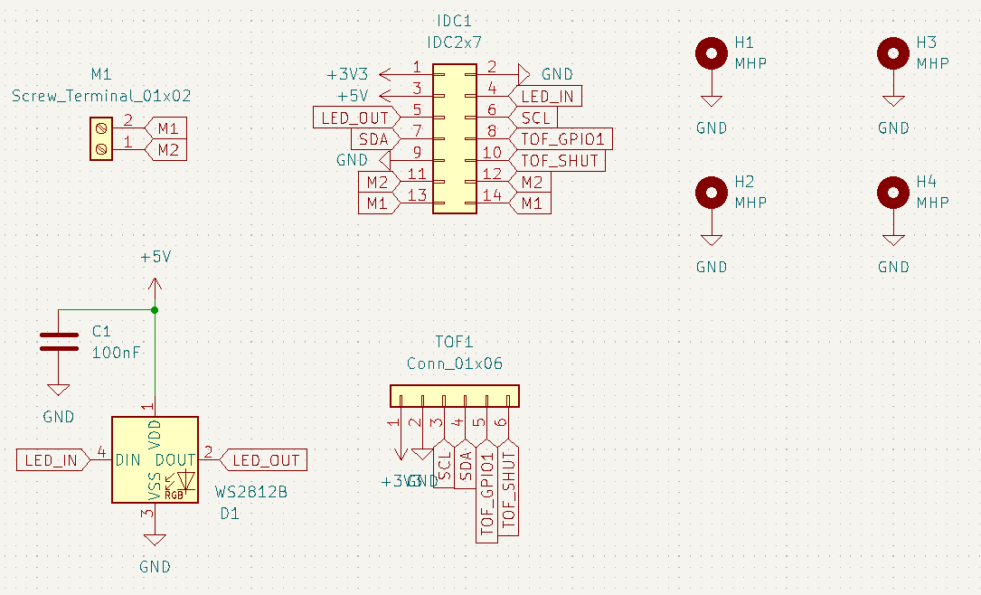
At the second end of IDC cable is small PCB which connects signals from the IDC connector to motor connected using terminal block, ToF sensor and there is also WS2815 RGB addressable LED but I did not implemented support for it in firmware yet. There are also 4 mountpoints with pitch exactly 1 cm so modules exactly match building set parts.
Schematic of module is following (it is also available to download as PDF at the end of blog post):
And PCB layout:
This PCB is technically ok, but I want to make new revision. Except swapping SDA and SCL as I mentioned above I also want to swap power supply pin or make their orientation jumper selectable. I originally designed to make this module working with Chinese VL53L0X modules but later I was considering using newer VL53L4CD rather. VL53L4CD is available on nice SATEL board from ST which has very similar pinout to Chinese module. It has only one difference when comparing to older Chinese module – swapped power pins. So for newer revision I will try to place some jumpers for selecting orientation of 3.3V and GND for ToF, swap SDA and SCL and finally I want to add additional decoupling capacitor for ToF Module (currently there are decoupling capacitor only for LED. I assumed that Chinese module would have own decoupling capacitor on board, but it is not as good as I expected).
ToF Sensors
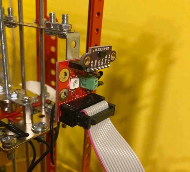
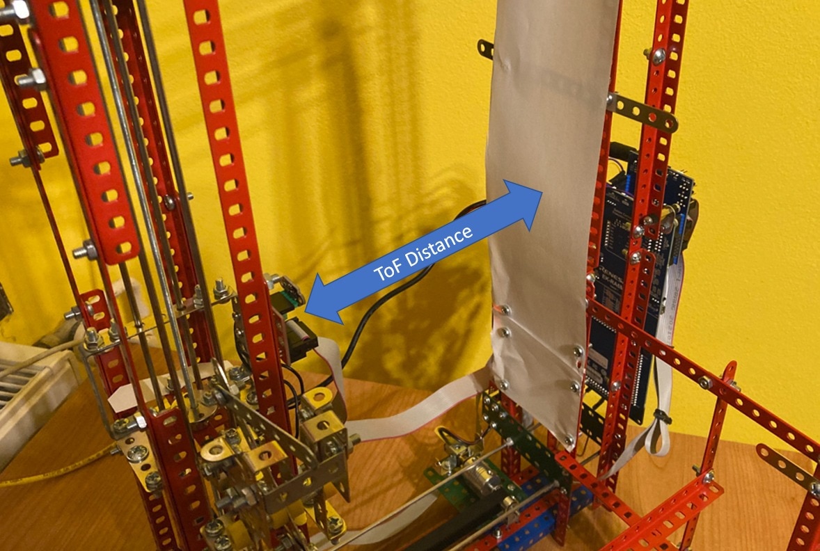
As I mentioned above, for detecting position of mechanical components, I use two ST VL53L0X Time of Flight sensors. For this reason, construction is covered by paper. This paper makes reference base for ToFs.
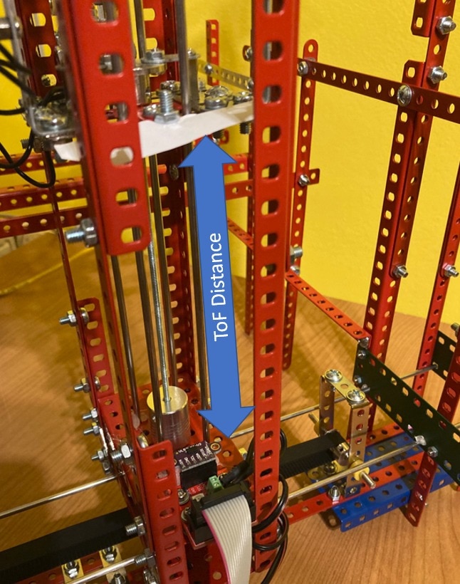
Second ToF measure vertical distance:
Firmware
Another important part of the whole device is firmware for Renesas RA6M4 microcontroller which controls whole device. It is based on FreeRTOS with TCP stack and runs manually implemented minimalistic HTTP server. HTTP can be used for triggering actions like moving motors to the target destination or reading actual values from ToF sensors.
Because I had to use different module for driving motor and I switch solenoid using transistor, then current firmware does not work as I originally expected and after I receive and solder MAX14871 motor drivers then I will need to rewrite some logic a little but I designed my source codes to be easily modified after this migration.
Firmware currently use three threads:
- Network thread for managing HTTP server and handling clients
- ToF thread for managing I2C communication with sensors
- Motor thread for enabling motors and controlling speed and direction. This thread also handles process of navigating parts to target destination according to ToF data.
- Solenoid thread which switches GPIO for a short period of time when push operation is requested. This will need to be reimplemented when switched to MAX14871 instead of basic transistor.
HTTP API
After detecting link activity on ethernet device will immediately start HTTP server with REST API. REST API supports following methods:
- /tofdata returns actual distances measured by ToF sensors or -1 in case of error. API method is used only for debugging.
- /m1fwd set motor 1 direction to forward and enables it for 3 seconds. It is used only for debugging. Motor 1 is used for vertical movement.
- /m1bwd similar to m1fwd but reverse direction.
- /m2fwd similar to m1fwd but start second motor which is used for horizontal movement.
- /m2fwd similar to m2fwd but reverse direction.
- /reach/H_pos/V_pos where H_pos is number indicating horizontal target distance from ToF and V_pos is number indicating vertical target distance from ToF. This operation start process of reaching vertical and horizontal destination. Motors are in this mode driven automatically by firmware. After reaching position it will push box by solenoid. When reaching destination, it is prohibited to use operations mXfwd and mXbwd. They will return error and report “Motor is busy” error message at this time. It is possible to use /tofdata service for checking progress. Using push service is possible but not recommended while reach process is in progress.
- /push push solenoid
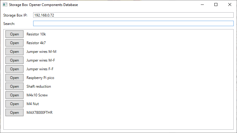
Simple Components Database PC Program
For getting full user experience from this device, I wrote simple program for managing components database. It loads database from text file, allows you to search for part and then over HTTP API triggers actions for navigating to the target box and opening them.
Text file is standard CSV. Values are separated by comma. First value is component name, second is horizontal position of box containing part and third is vertical position.
BOM and Cost
As part of project, I had to buy lot of components. I had to buy many building set extension kits because I very soon exhausted parts which I already had. I had to order ToF modules, order PCBs and components for them. I also ordered some parts which I later decided to do not use. List of electronics parts BOM for PCBs is in separate CSV file at the end of this blog post. Here I will omit most of them because it is exhaustive list of over 80 capacitors, resistors, connectors, jumpers, … Prices include minimum order quantity, but quantity column does not (quantity column describes count required for completing project, price column shows price which I paid for product). I ordered some parts in local store, so some currencies are in CZK. For this reason, there is last column which normalize all prices to USD. Last row sums the total price (not including passive components for PCBs).
|
Part |
Quantity |
Price (native currency) |
Price (USD equivalent) |
|
Building set extension Kit Merkur ND 101 |
1 |
139 CZK |
5.63 USD |
|
Building set extension Kit Merkur ND 103 |
1 |
85 CZK |
3.44 USD |
|
Building set extension Kit Merkur ND 107 |
1 |
89 CZK |
3.60 USD |
|
Building set extension Kit Merkur ND 109 |
1 |
149 CZK |
6.03 USD |
|
Building set extension Kit Merkur ND 110 |
1 |
199 CZK |
8.06 USD |
|
M4x10 screws |
250 |
~ 220 CZK |
8.91 USD |
|
M4 nuts |
200 |
~ 160 CZK |
6.48 USD |
|
M3x6 screws |
50 |
0.96 USD |
0.96 USD |
|
M3x5 plastic standoff |
20 |
0.57 USD |
0.57 USD |
|
M3x11 nickel standoff |
14 |
33.1 CZK |
1.34 USD |
|
M3x12 nickel standoff |
2 |
10 CZK |
0.40 USD |
|
M3x14 nickel standoff |
1 |
10 CZK |
0.40 USD |
|
Shaft reduction 3 mm to 3 mm (for attaching shaft/threaded rod to motor) |
2 |
4.40 USD |
4.40 USD |
|
3mm stainless rod |
4 x 1m |
96 CZK |
3.89 USD |
|
M3 threaded rod |
1m |
7.5 CZK |
0.30 USD |
|
hacksaw |
1 |
159 CZK |
6.44 USD |
|
vice |
1 |
65 CZK |
2.63 USD |
|
N20 electromotor |
2 |
5.15 USD |
5.15 USD |
|
Solenoid |
1 |
199 CZK |
8.06 USD |
|
Gear belt 640 mm |
1 |
3.8 USD |
3.80 USD |
|
Gear belt shaft holder |
2 |
3.22 USD |
3.22 USD |
|
Flange nut M3 |
1 |
4.21 USD |
4.21 USD |
|
Shield PCB |
1 |
9.68 USD |
9.68 USD |
|
Module PCB |
3 |
2.42 USD |
2.42 USD |
|
IDC connector 7x2 |
6 |
38.32 CZK |
1.55 USD |
|
IDC cable 7x2 |
3 |
108.5 CZK |
4.39 USD |
|
5A Polymer fuse |
1 |
36.82 CZK |
1.49 USD |
|
1x6 pinsocket |
2 |
24.77 CZK |
1.00 USD |
|
Terminal block |
3 |
2.30 USD |
2.30 USD |
|
2 mm Hex screwdriver |
1 |
90.71 CZK |
3.67 USD |
|
MAX16935CAUESB/V+ |
1 |
Free sample |
0.00 USD |
|
MAX5715BAUD+ |
1 |
Free sample |
0.00 USD |
|
MAX14871EUE+ |
3 |
Free sample + 312.5 CZK |
12.65 USD |
|
Renesas EK-RA6M4 |
1 |
Free sample |
0.00 USD |
|
Elevated socket strip 1x6 |
1 |
Free sample |
0.00 USD |
|
Elevated socket strip 1x8 |
3 |
Free sample |
0.00 USD |
|
Pin header 1x48 |
1 |
Already have |
0.00 USD |
|
0603 Red LED |
1 |
Already have |
0.00 USD |
|
0603 Amber LED |
3 |
43.62 CZK |
1.77 USD |
|
Terminal block 1x2 2.54mm |
3 |
2.3 USD |
2.30 USD |
|
VL53L0X ToF Sensor Module |
2 |
3.4 USD |
3.40 USD |
|
Shipping store #1 |
1 |
114.95 CZK |
4.65 USD |
|
Shipping store #2 |
1 |
129 CZK |
5.22 USD |
|
Shipping store #3 |
1 |
4.85 USD |
4.85 USD |
|
Shipping Farnell |
1 |
211.75 CZK |
8.57 USD |
|
Total |
|
|
157.83 USD |
Summary
This project was huge. It consists of lot of work when building mechanical construction. I of course did not build whole construction at the first attempt but rather I build some prototype and then improved them. Building final mechanical construction took me over month. At the end I consider this construction as more reliable than I originally expected. The slightly problematic is lever for pushing boxes because nuts on screws freely unscrew due to vibrations. I had to make some patches for making constructions and especially moving parts. I started thinking about project right after theme come from poll even before main page of this competition was created. Very soon I started to design PCBs, order components and think about mechanical construction. At the end I was writing firmware. It took me over 2 months of almost every afternoon to build this project. It is huge but I learnt a lot. I especially learnt working with electromotors, solenoid and I improved my mechanical skills when designing and building this big construction. It cost me a more money than I originally expected. I also bought some parts which I later decided to do not use, so price was even slightly higher than previous BOM mention. In opposition free samples from Renesas, Maxim Integrated and Samtec significantly helped me. Currently I am satisfied with the project. Later I will reimplement device to use MAX14871 motor drivers as I originally planned, and I also want to change ToF sensor to newer VL53L4CD on SATEL board and for this reason I will in near future make new revision of one PCB.
At the end I would again thank Renesas, Maxim Integrated (ADI) and Samtec for sending me free samples and also, I would like to thank all readers of this blog for their time. Feel free to comment or give me feedback on this project in comments bellow.
EDIT 2023-06-04
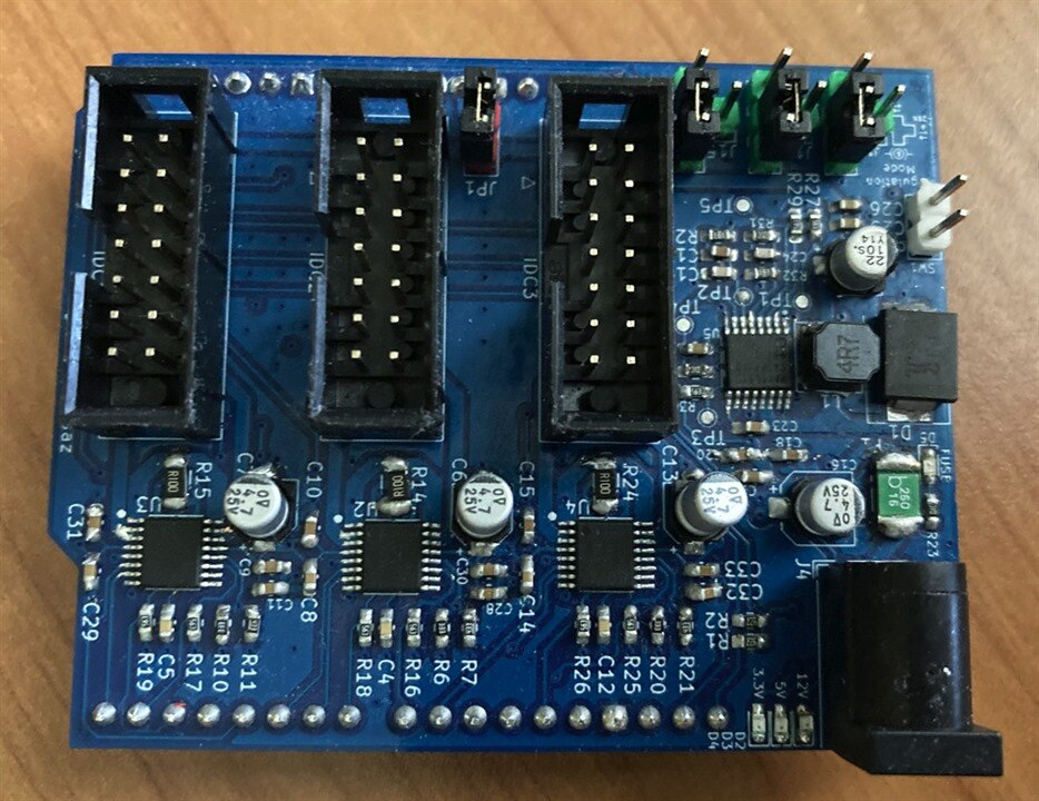
Since this project was low priority for me, it took a very long to update the project with promised changes. But today I completed it. I replaced the DIY motor driver by MAX14871 and results are better because it features several nice features like ramp-up on start-up and also feature several safety features like short circuit protection. Also, I was able to test software defined current limit which my shield offers when used with MAX14871 as designed. MAX14871 allows current limiting configured using reference voltage and onboard DAC allows configure this limit by software. Works very well. Fully assembled shield with MAX14871 Motor drivers looks as follows:
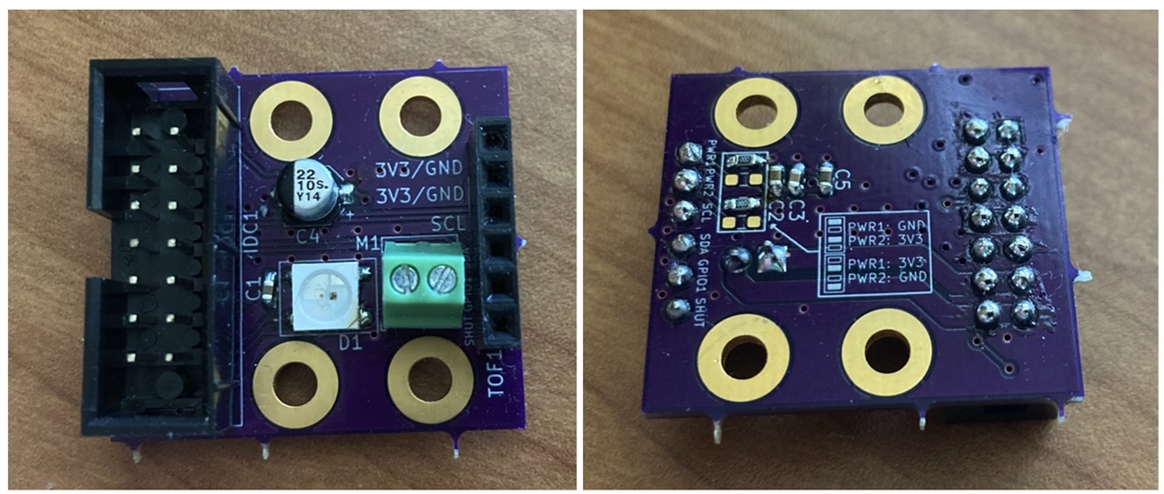
I also assembled and tested new module PCB which fix SDA and SCL swap and also enables to configure (using zero-ohm resistors) power pins connected to VCC and GND allowing swapping them and using both Chinese VL53L0X ToF modules as well as VL53L4 Satel Boards from ST. From end user perspective very, few things change, and usage looks exactly the same. Following photos shows the new revision of module PCB.
For using with MAX14871, new firmware (ver 2.0) is needed. It contains new support for driving PWM, EN and DIR pins as required by MAX14871, contains MAX5715 DAC library for setting motor current limit, contains refactored code and several bug fixes. The major bug fix resolves “overshoot” when the device reaching the destination and ToF Sensor fails. After the analysis and several experiments, I think this happens due to noise from motors. Using IDC cables with motor power wires and I2C wires on the same cable was not ideal and the same bad practise is used on the PCB. I did not realize it when designing original PCB. Next time I will separate motor wires more precisely from digital interfaces. Software fix is that when the ToF failure happens, program stops motors, tries to restart, and reinitialize failed sensor and then continue reaching destination. Hardware fix is replacing the most sensitive IDC cable to the vertically moved base by two cables splitting motor wires from digital one. This hardware fix almost resolves the issue, but sensor failures still occur spuriously. Another (easy) hardware fix which slightly reduce the problem impact is decreasing the I2C pullups from 4k7 as used in schematics to 1k5.
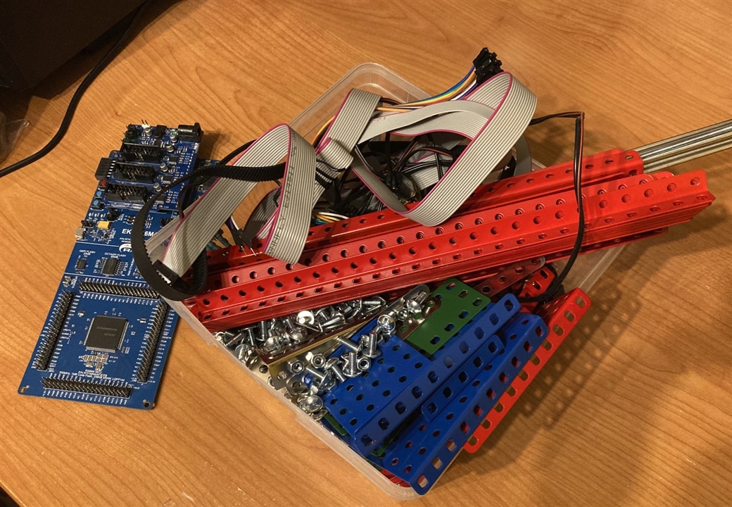
Finally, after the almost year I disassembled the device.  It is nice device, and I learnt a lot when designing, programming, and playing with it but it is quite a big and almost double the physical dimension of storage cabined. After year it was very dusted, and it is hard to precisely clean the construction as designed. So, I decided to disassemble it. Now it looks as follows:
Resources and Downloads
- Shield schematics (PDF)
- Shield gerbers (ZIP)
- Shield Kicad project (ZIP)
- Shield BOM (CSV)
- (old version) Module rev 1 schematics (PDF)
- (old version) Module rev 1 gerbers (ZIP)
- (old version) Module rev 1 Kicad project (ZIP)
- (old version) Module rev 1 BOM (CSV)
- Module rev 2 schematics (PDF)
- Module rev 2 gerbers (ZIP)
- Module rev 2 Kicad project (ZIP)
- Module rev 2 BOM (CSV)
- (old version) Firmware rev 1 source codes (ZIP)
- (old version) Firmware rev 1 build (ELF)
- Firmware rev 2 source codes (ZIP)
- Firmware rev 2 build (ELF)
- PC program source codes (ZIP)
- PC program binaries (ZIP)


