Hello everyone.
I welcome you to the blog describing my last experiment which I promised in my first blog post as part of Experimenting with Current Sense Amplifiers Design Challenge. In blogs #2, #3 and #4 I shown basic usage of MAX40080 Current Sense Amplifier sensor. Then in blog posts #5, #6 and #7 I introduced my libraries which I created as part contest for simplifying usage of MAX40080 CSA sensor. In blog post #8 I introduced my CLI utility for allowing use MAX40080 CSA without need of programming. In blogs #9 and #10 I shown my experiments ending with analysis self-collected power consumption of Raspberry Pi. In previous blog #11 I shown my main experiment as part of this contest and in this 12th blog post I will show my last promised experiment.
In this experiment I will use MAX40080 CSA on MikroE current 6 Click Board for long time monitoring power consumption of barrel jack powered device. In this experiment I will use Renesas EK-RA6M4 board with RA6M4 microcontroller and ethernet connectivity. I will use HTTP server available over Ethernet for accessing long term statistics. I will also use MAX31343 RTC for providing time to log outputs.
Sample sponsors
In this experiment I used Renesas EK-RA6M4 board featuring Ethernet connectivity which I received for free as a free sample from Renesas. It is similar board to EK-RA2L1 which I have RoadTested last year but EK-RA6M4 featuring more advanced and more performant MCU with Cortex-M33 CPU core, onboard large Flash memories which I will use in this experiment for storing measured data and Ethernet connectivity which I will use for accessing log outputs over web. Thank Renesas for sending this board for free.

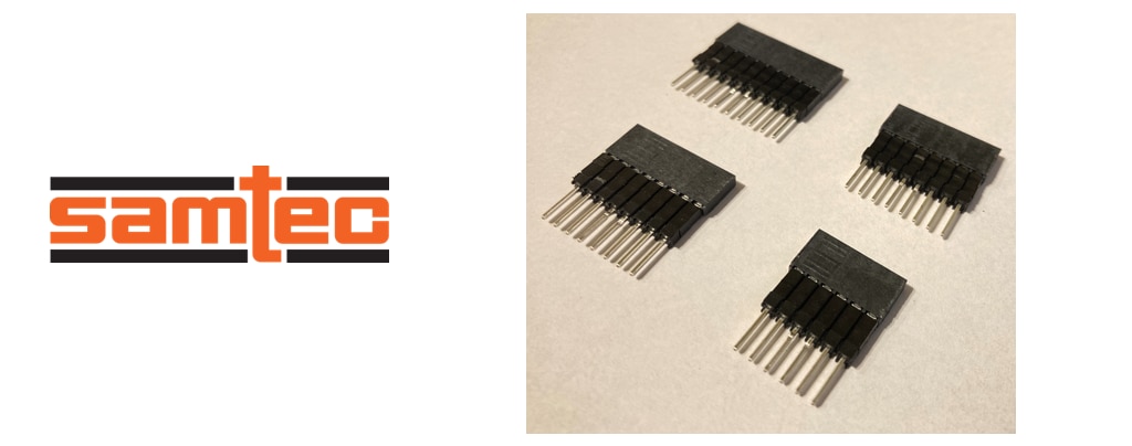
Because terminal block of Current 6 Click on the board collided with MAX31343 RTC Arduino Shield I also ordered free samples of Samtec elevated socket strips ESQ-106-34-L-S-LL, ESQ-108-34-L-S-LL and ESQ-110-34-L-S-LL (codes differ in number of pins) for solving this mechanical collision. By mistake I chosen -LL variants with looking leads but after receiving them I realized this as an advantage because locking lead makes small gap in the socket which can be used for example for connecting oscilloscope or analyser on the exposed part of pins. Also, with locking lead socket is easier to remove. Thank Samtec for sending these connectors for free.
Features and Firmware Implementation
I wrote firmware for Renesas RA6M4 MCU using FreeRTOS with TCP stack. I developed firmware using e^2 studio provided by Renesas. For accessing MAX40080 CSA and MAX31343 I used my own libraries. MAX40080 C Library I described in blog post #6 and MAX31343 C Library I created as part of MAX31343SHLD RoadTest last year and it is also available at Github. I considered using internal RTC of RA6M4 MCU but shield use supercapacitor instead of 3V (CR2032) battery which I consider as a better choice because supercap do not require any user maintaince and do not require providing any battery. Disadvantage is that I need to use I2C communication with RTC chip in comparison with directly accessible RTC as part of MCU on the system bus.
As part of firmware, I manually implemented simple HTTP server for serving HTML page and loged data. Implementation of HTTP server is minimalistic and experimental grade. I support only few features of HTTP protocol and I am support only oldest HTTP version. My implementation is based on directly calling socket functions provided by Renesas’s port of FreeRTOS with TCP stack bundled as Renesas FSP (Flexible Support Package) in Renesas e^2 studio. HTTP implementation is very trivial but working for this task. I did not utilize any complex HTTP library.
For reading and writing data to Flash memory I used fragments of code from example provided by Renesas.
Because I used RTOS, I used threads for controlling MAX40080 CSA, thread for loading and saving data from flash and I created threads dynamically for handling HTTP requests from clients.
MAX40080 CSA Configuration
In this experiment I configured MAX40080 CSA slightly differently than in previous experiments. I configured it by following parameters:
- I used Selected Active Mode instead of Active mode. Selected Active Mode is designed for taking only few samples per second (4 in my case) and between measurements it turns sensor to low power mode. In my experiment this mode is useful because reduces power consumption of sensor (in fact this is irrelevant because Click Board has LED which is the most significant source of power consumption, but imagine using other board where MAX40080 is the most significant source of power consumption). Similarly, because I am measuring long term power consumption, I do not worry about details much. At least I had to consider capacity of FLASH memory for storing data, so I can’t save all the samples and it does not make sense to sample faster.
- Like in previous experiment I will use interrupts and overflow warning feature for indicating available sample. I will take every sample rather than waiting for 5 samples, like I did in previous experiment.
- I am using Packet Error Checking feature of chip and my library computes and checks CRC of received packets.
- Input Range I let configurable. It can be changed over HTTP API.
- I disabled digital filter because sample rate 4 sps generate by Selected Active Mode are insufficient to any meaningful digital filtering on chip side. Instead, I will average samples (with saving some other statistics like max and min) on MCU side for reducing data stored in FLASH.
- In the FIFO I store both current and voltage which is possible in Selected Active Mode without any other restriction (sample rate has no effect in this mode).
Connection
Board has both MikroE socket and connectors matching Arduino Shield pinout. Connection in this way was easy. But because Click Board is in the centre of the shield and contains large terminal block, it collided with shield, and I had to use elevated socket strips for extending connectors height. After connecting it looks like this:
For adding barrel jacks, I used jack socket with soldered wires:
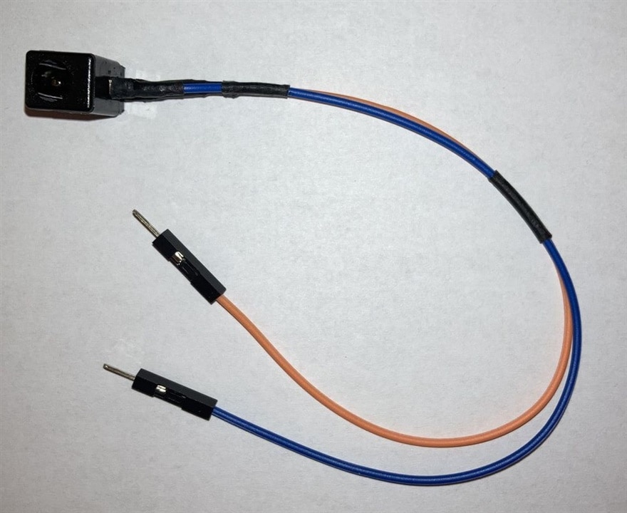
And for male side I bought short cable with connector:

Then I connected cables to the sensor in following way:
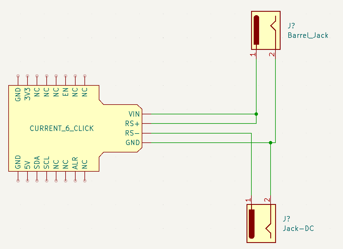
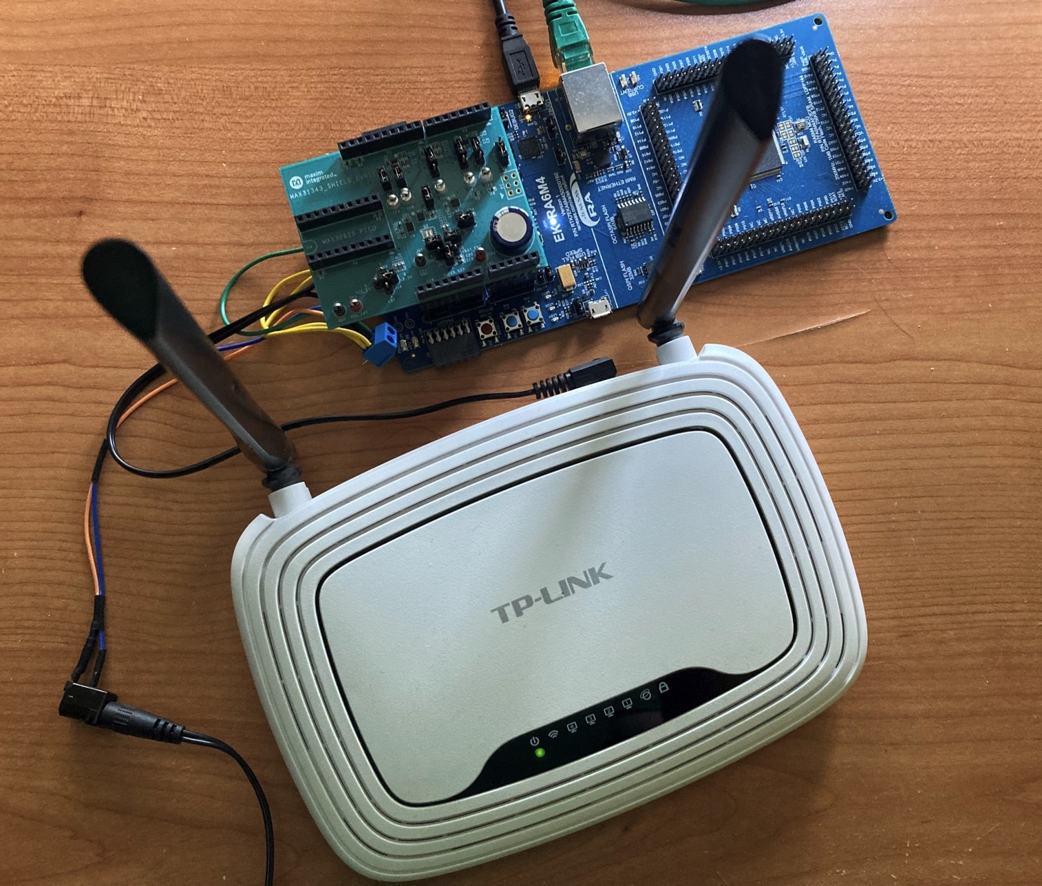
I used terminal block for making junctions instead of connecting circuit on unreliable breadboard again. In real world connection look like this:

And finally, after plugging power supply and device:
Saving data to flash
Source code responsible for storing data to the flash is quite complicated while format is quite easy. I store things which I refer as a DayLog. DayLog has array of floats for storing minimum, maximum and average voltage and current. So, structure has 6 float arrays. Values are accumulated over 5 minute intervals and after 5 minute interval accumulated data are written to DayLog and stored in 64 MiB Octal SPI Flash Memory on EK-RA6M4 board. Except float arrays there is array for storing flags indicating validity of float value in specified 5-minute range (for example when device is powered off, there will not be any valid value in corresponding time slot) and finally, it has header (in fact it is footer because I let float arrays aligned) indicating year, month and day of DayLog entry. At midnight after flushing of last 5 minut interval, firmware start collecting data for first 5 minute interval of the new day and after collecting it, it creates new DayLog entry for this day new day filled with first entry. Firmware specify Flash storage boundary to 31 days. After 31 days when all DayLog cells became full, firmware selects oldest entry and erase it for making space for new day. Constant can be changed and can be extended to more than year (365 days), but for now I let it se to 31 days. Data consumption can be calculated as 6 (float arrays) * 12 (every hour have twelve 5-minute intervals) * 24 (day have 24 hours) * 4 (size of float) + 12 (every hour have twelve 5-minute intervals) * 24 (day have 24 hours) * 1 (size of flag) + 3 (year, month and date) = 7203 Bytes. For simplifying firmware, I am padding structure to 8192 Bytes for easier erasure and patching flash cells. This results, that maximum permissible capacity is for 64 MiB / 8 KiB = 8192 days = more than 22 years. But as I said, for easier testing I chosen limit of 31 days for now.
Web Interface
HTTP Interface is implemented as REST API and index.html page containing JavaScript code which access and show data received from REST API. When you open IP address of device in browser you will see something like this:
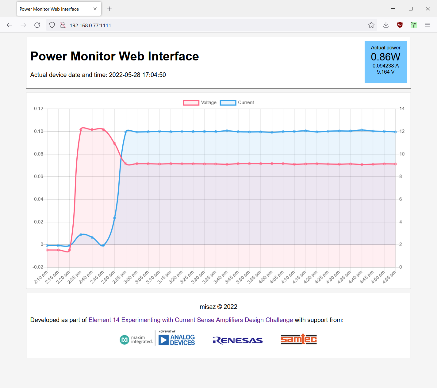
JavaScript is responsible for refreshment of visualized information. Time is regularly updated from the device and right blue box with information about actual power is also regularly refreshed. Screesnhot above comes from time few hours after I developed device. At beginning I have not connected any input to it (so voltage and current are near zero. Then I for testing barrel jack connected 12V power supply to it. After few minutes I for testing connected DC/DC regulator (without load), so only its LED caused power consumption of about 15 mA which is visible on plots. Finally, then I disconnected all these testing devices and connected 9V power supply and Wi-Fi router to it. All these changes are visible here. I tried to load Wi-Fi router but high traffic on both Wi-Fi and ethernet did not caused any significantly visible power consumption increase. Consequently, it is easy to estimate power consumption. You can just collect power consumption for few days, see averages and recalculate it with price of electricity. It is not very accurate because for example efficiency of AC/DC converter also comes in play, but for estimation this is still good.
Internal REST API
Web Application uses REST API at the same endpoint as index.html is provided. You can for example open /getttime page for getting time from MAX31343 RTC:

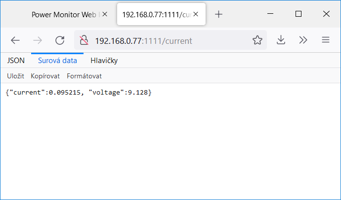
Similarly, you can read last collected sample from CSA:
Or history from last one day:
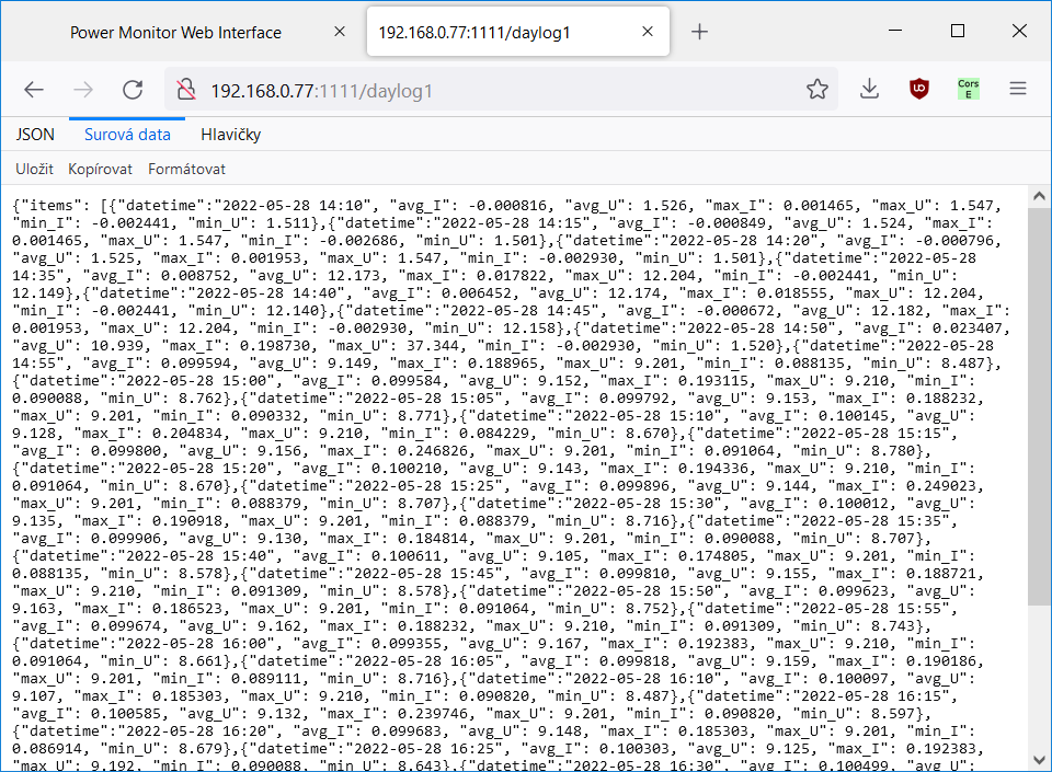
As you can see, firmware export data in JSON format, so they can be easily parsed.
Except HTTP services shown above, there are some internal services which are not directly used by main page but can be used for configuring or debugging. There are following services:
- settime: allows setting time in MAX31343 when device is started first time. Parameters are passed in URL. For setting date and time to 2045-08-05 11:22:33 open following webpage http://IPaddr:1111/settime/2045/08/05/11/22/33
- gettime: prints current time from MAX31343 RTC
- current: prints last measurement collected from MAX40080 CSA
- dumpflash: download binary file containing first 32 KiB of OSPI Flash. Used when debugging.
- daylog1: provides collected data from last day
- daylog7: provides collected data from last 7 days
- daylog30: provides collected data from last 30 days
- eraseall: Erase all loged data
Summary
In this blog post you have seen my additional experimental project. It was the last project which I promised in my first blog as part of this contest. This project was more complicated on software side rather than on configuration of CSA. In next blog post I will post summary of one issue with MAX40080 which I have faced when experimenting with MAX40080. Then I will post some summary over all my experiments and blog posts which I posted as part of this fantastic contest. Contest deadline is today, so I will complete and post these blogposts also today.
Thank you for your patience and stay tuned to my last blog posts. Using link below you can download source code and binary of firmware which I shown in this blog post.
Resources
- MAX40080 C Library (Github)
- MAX31343 C Library (Github)
- Firmware source code (ZIP)
- Firmware binary (ELF)
Next blog: Blog #13: MAX40080 Samples corruption when FIFO Roll-over mode enabled

