


Intro
This is another example of using both inputs and outputs of the Analog Discovery 3 to test a circuit.
This example also uses a TI LM2907 frequency-to-voltage converter chip but it is configured as a capacitance to voltage converter. I use the Digilent AD3 to generate a constant frequency for the capacitance to voltage circuit and a second output to generate a PWM signal to drive a motor. The motor is controlling the height of a beaker of water while the capacitance circuit is measuring the height of the beaker or depth of water.
Motorized Water Level Sensor Demo
Capacitance to Voltage Schematic
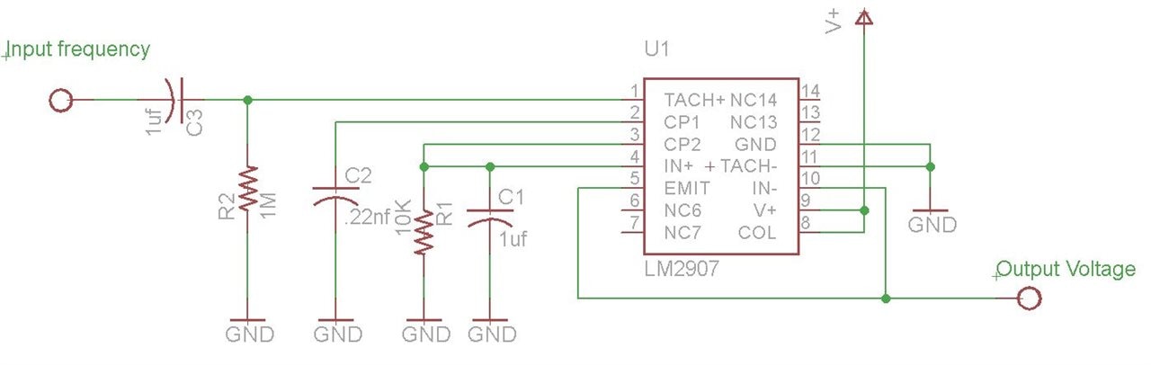
VO = VCC × fIN × C2 × R1 × K
This formula indicates the output voltage is proportional to both capacitance and frequency, so in this case the frequency is constant and C2 is a variable capacitance probe, which makes the output proportional to immersion depth in water.
Discussion
The Analog Discovery 3 does a great job of both running the water depth circuit and controlling the motorized scissor jack - at the same time. To do this with conventional instrumentation would involve a lot more instruments.
Links:
Pretty Cool Raster Text Display on an AD3
AD# - Frequency-to-Voltage Converter
AD3 - Capacitance-to-Voltage Converter
Digilent Analog Discovery 3 Road Test


