element14 Community
element14 Community
    Register Log In
  • Site
  • Search
  • Log In Register
  • About Us
  • Community Hub
    Community Hub
    • What's New on element14
    • Feedback and Support
    • Benefits of Membership
    • Personal Blogs
    • Members Area
    • Achievement Levels
  • Learn
    Learn
    • Ask an Expert
    • eBooks
    • element14 presents
    • Learning Center
    • Tech Spotlight
    • STEM Academy
    • Webinars, Training and Events
    • Learning Groups
  • Technologies
    Technologies
    • 3D Printing
    • FPGA
    • Industrial Automation
    • Internet of Things
    • Power & Energy
    • Sensors
    • Technology Groups
  • Challenges & Projects
    Challenges & Projects
    • Design Challenges
    • element14 presents Projects
    • Project14
    • Arduino Projects
    • Raspberry Pi Projects
    • Project Groups
  • Products
    Products
    • Arduino
    • Avnet Boards Community
    • Dev Tools
    • Manufacturers
    • Multicomp Pro
    • Product Groups
    • Raspberry Pi
    • RoadTests & Reviews
  • Store
    Store
    • Visit Your Store
    • Choose another store...
      • Europe
      •  Austria (German)
      •  Belgium (Dutch, French)
      •  Bulgaria (Bulgarian)
      •  Czech Republic (Czech)
      •  Denmark (Danish)
      •  Estonia (Estonian)
      •  Finland (Finnish)
      •  France (French)
      •  Germany (German)
      •  Hungary (Hungarian)
      •  Ireland
      •  Israel
      •  Italy (Italian)
      •  Latvia (Latvian)
      •  
      •  Lithuania (Lithuanian)
      •  Netherlands (Dutch)
      •  Norway (Norwegian)
      •  Poland (Polish)
      •  Portugal (Portuguese)
      •  Romania (Romanian)
      •  Russia (Russian)
      •  Slovakia (Slovak)
      •  Slovenia (Slovenian)
      •  Spain (Spanish)
      •  Sweden (Swedish)
      •  Switzerland(German, French)
      •  Turkey (Turkish)
      •  United Kingdom
      • Asia Pacific
      •  Australia
      •  China
      •  Hong Kong
      •  India
      •  Korea (Korean)
      •  Malaysia
      •  New Zealand
      •  Philippines
      •  Singapore
      •  Taiwan
      •  Thailand (Thai)
      • Americas
      •  Brazil (Portuguese)
      •  Canada
      •  Mexico (Spanish)
      •  United States
      Can't find the country/region you're looking for? Visit our export site or find a local distributor.
  • Translate
  • Profile
  • Settings
Community Hub
Community Hub
Member's Forum Using 12v at base of transistor
  • Blog
  • Forum
  • Documents
  • Quiz
  • Events
  • Leaderboard
  • Polls
  • Files
  • Members
  • Mentions
  • Sub-Groups
  • Tags
  • More
  • Cancel
  • New
Join Community Hub to participate - click to join for free!
Actions
  • Share
  • More
  • Cancel
Forum Thread Details
  • State Verified Answer
  • Replies 29 replies
  • Answers 10 answers
  • Subscribers 539 subscribers
  • Views 6234 views
  • Users 0 members are here
  • transistor
  • 12v
  • car
Related

Using 12v at base of transistor

ntewinkel
ntewinkel over 9 years ago

Hi all,


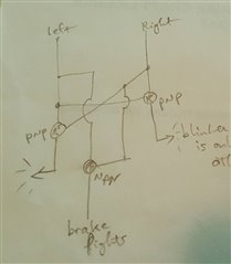
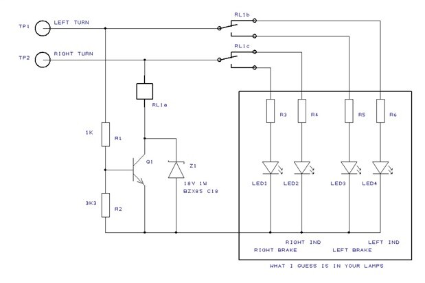
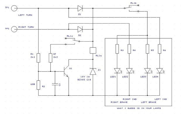
I'm thinking of using a transistor in a car circuit, to switch a light depending on the state of another light.


So it will be 12v as the signal at the base of the transistor.


I have a bunch of pn2222a transistors, and I can't figure out from the datasheet what the maximum means for that. It seems to be a reverse maximum (ie, don't let the output be more than 5v over the base voltage).


So the question is - is it possible to switch a transistor like that using 12v at the base?


Thanks!

-Nico


ps, I know I can easily do this using relays, but those take up more space, and I'd prefer to avoid the mechanical bits.

  • Sign in to reply
  • Cancel

Top Replies

  • michaelkellett
    michaelkellett over 9 years ago +2 verified
    Short answer - no. The base of a transistor is current driven - think of the base emitter junction as being a diode (the arrow on the emitter shows the direction of conventional current when forward biased…
  • ntewinkel
    ntewinkel over 9 years ago in reply to michaelkellett +2
    Thanks Michael! To be more precise with the details, they are to switch the LED taillights on a camper trailer. I should test how much it draws. The description said 3W, but that might be for the whole…
  • D_Hersey
    D_Hersey over 9 years ago +2 suggested
    Maybe there is a POTS soln: How To Install A Trailer Light Taillight Converter In Your Towing Vehicle I am not quite sure how the brake light signal is derived from turn signals. If you can come up with…
Parents
  • ntewinkel
    0 ntewinkel over 9 years ago

    Dang, I just realized a logic error in my design!! Noooo!!


    Consider brakes are on at an intersection, and turning right.


    I just tested this on the 4-wire tailer harness in the car.


    In that case the left light stays on, and the right light flashes - and by that I mean there's steady 12v on the left wire, with 12v/0v on the right wire.


    Using my logic, when both lights are on, the red brake lights will be on (good),

    BUT when the flashing right light is off, the left light will be the only one on, which using my logic, will make it show the left orange arrow...


    so then the result looks like "red brake lights" intermittent with "left orange turn light"... giving the impression that we're turning in the opposite direction that we're actually going.


    Dang!

    This just got a whole lot more complicated!


    Anyone have any brilliant ideas?


    Maybe a large capacitor can keep the "signal" high for enough time to allow the other side to flash without switching to the orange arrow. But then the right turn would only flash the red light, not the arrow. Which is no different from how a regular trailer does it.


    I could also run an extra line from the car for the brake signal, but that would be non-standard and the trailer would still have to handle the case where some other vehicle is towing it.


    I'm wondering if I need to step this up to microcontroller control. The microcontroller can be kept powered on from the trailer battery. But then the failsafe (controller off or dead) needs to still give some sort of proper indications.


    For the time being I might just wire up the arrow and the red part together, with the side effect being that the brake signal will include both orange arrows on.


    Thanks,

    -Nico

    • Cancel
    • Vote Up 0 Vote Down
    • Sign in to reply
    • Verify Answer
    • Cancel
  • ntewinkel
    0 ntewinkel over 9 years ago in reply to ntewinkel

    ps, this is the circuit I had:

    image


    And a video showing how all works well until you press the brakes (both switches on) while blinking one side:

    You don't have permission to edit metadata of this video.
    Edit media
    x
    image
    Upload Preview
    image

    • Cancel
    • Vote Up 0 Vote Down
    • Sign in to reply
    • Verify Answer
    • Cancel
  • michaelkellett
    0 michaelkellett over 9 years ago in reply to ntewinkel

    Hello Nico,


    Here's my scheme:


    image

    The relay can be any 12V coil double pole change over (often called DPDT)  you fancy. The coil resistance should be at least 100R if you want to use up your pn2222a transistors.


    The relay will only be energised when both turns inputs are high and the brake lights get the power. If only one turn input is high then the turn indicators get power.


    With R1 and R2 as shown the turn on threshold for Q1 on the LT input is only about 0.8V, you could reduce R2 to 100R which would set the threshold at 6V or so.

    The transistor only switches the relay coil current and is protected against supply spikes and relay coil inductive spikes by Z1.

    A small capacitor (100nF ceramic) from Q1 base to emitter wouldn't hurt and might reduce sensitivity to electrical noise.


    MK

    • Cancel
    • Vote Up +1 Vote Down
    • Sign in to reply
    • Verify Answer
    • Reject Answer
    • Cancel
  • ntewinkel
    0 ntewinkel over 9 years ago in reply to michaelkellett

    Thanks Michael! That looks really good, much better than my sketch image  Are you using special software for that?


    For the resulting behaviour, am I looking at it wrong, or would it have a similar problem as my first prototype? - what happens when the brakes are on and the blinker is on at the same time?


    For example, brakes are on, and the left turn signal is on. That means TP2 stays at 12v and TP1 alternates between 0v and 12v.

    First, both TP1 and TP2 are on, the relay is energized and both red brake lights are on.

    Then TP1 is off, TP2 is still on, meaning the relay is off and the right indicator orange light is on, the left brake and signal lights are both off.


    The result is that the taillights alternate between having 2 red brake lights and the orange right turn indicator (opposite of the actual signal indicated by the tow vehicle).


    I'm hoping I'm overlooking something image


    Thanks,

    -Nico

    • Cancel
    • Vote Up 0 Vote Down
    • Sign in to reply
    • Verify Answer
    • Cancel
  • michaelkellett
    0 michaelkellett over 9 years ago in reply to ntewinkel

    Hello Nico - you are correct - I hadn't registered that problem correctly.

    I think I can tweak it so that it's fixed.


    The software I use for pcbs is EasyPC - by far the best cheap PCB CAD that I'm aware of - it doesn't do everything but what it does it does very well.


    I'll post mk2 in a bit.


    MK

    • Cancel
    • Vote Up +1 Vote Down
    • Sign in to reply
    • Verify Answer
    • Reject Answer
    • Cancel
  • michaelkellett
    0 michaelkellett over 9 years ago in reply to michaelkellett

    Hello Nico,


    Here's a better design - two extra diodes but the relay only needs to be DPST so will be cheaper and easier to find.


    image


    I think this nearly does what you want - if only one input is high the appropriate turn light comes on, if both inputs are high the relay energizes and the brake lights come on (but so do the turn lights), the brake lights stay on until both inputs go low because the c terminals on the relay hold it on so long as there is power through either diode.


    I don't really like the turn lights coming on at all when braking but this gets much harder since you need quite a lot of 'statefullness' in the controller - are you up for a micro ?


    MK

    • Cancel
    • Vote Up +1 Vote Down
    • Sign in to reply
    • Verify Answer
    • Reject Answer
    • Cancel
  • ntewinkel
    0 ntewinkel over 9 years ago in reply to michaelkellett

    That's really good, Michael!

    You're right about the turn lights coming on when braking being a bit annoying, and might be confusing to other drivers.

    It's similar to hooking up the wires directly to the red and orange lights together, but gains the benefit that signals are only using the orange.


    ...this gets much harder since you need quite a lot of 'statefullness' in the controller...

    That's the conclusion I came to as well.

    It seems that the only way to tell if it's a turn signal is by the flashing action.


    are you up for a micro ?

    But of course! That's probably where I'm most comfortable. My worries are that the micro would have to start up very fast, or else be kept powered up by an alternate source. I'm guessing that a capacitor would keep it running long enough between blinks though. After that it should be possible to determine when a light has been on and off, and then flash the orange indicator on the transition from 0v to 12v, maybe missing the first flash, but that's ok.


    ps, the trailer does have it's own 12v power source too, so that could be used to power it, however, the failure mode (ie, no trailer power available) should provide safe function still (maybe just using the red lights, as would be the usual for trailers).


    Maybe the easiest way to handle it is to add two lines from the car turn indicator wires to directly control the orange turn indicators.


    Thanks,

    -Nico


    • Cancel
    • Vote Up 0 Vote Down
    • Sign in to reply
    • Verify Answer
    • Cancel
  • michaelkellett
    0 michaelkellett over 9 years ago in reply to ntewinkel

    Hello Nico,


    Simple micros with on chip RC oscillators can be up an running in under 1mS quite easily - I don't think you need store power between blinks because if the brake is on there is always at least one turn signal high to provide power.


    Do you have  a micro preference - almost anything would do (PIC, AVR, ARM) and do you need it to be in a DIL package or are you OK with SO which would need a board. The whole thing will be much more reliable with a board of course.


    MK

    • Cancel
    • Vote Up 0 Vote Down
    • Sign in to reply
    • Verify Answer
    • Cancel
  • ntewinkel
    0 ntewinkel over 9 years ago in reply to michaelkellett

    Hi Michael,


    ...up and running in under 1mS quite easily

    That's really good to know.


    For the between-blinks power store I was thinking that would be needed for the case where it's just a turn indicator flashing (no brakes). Out of curiosity I might test to see how long one will run on a capacitor.


    Do you have  a micro preference

    I do have a micro preference, mostly due to laziness image  Because my stuff is pretty much all hobby I've decided to focus on Arduino and Raspberry Pi - I found that otherwise I end up spending my time learning new tools instead of building projects. I also have TI MSP430, and CCS isn't too bad, but Energia makes using those super simple too.


    I'm still at the DIP stage. I have a few surface mount ATTiny13 chips because I needed one for an art project (it's glued to a rock and "wired" with conductive glue).


    I haven't created any PCB's yet. A lot of my projects never go beyond breadboard, and the ones that did I've used perf board - a bit messy but worked well enough.


    I do have some nice little 3x2x1 inch project boxes that include perf board in it, that I bought from Radio Shack when they were clearing out all that stuff before they became "The Source" here in Canada. One of those might work well for this.


    In terms of controllers inventory, I have a couple of DigiSparks (ATTiny85 based) that might work well for this, or maybe one of the TI MSP430 chips because their DIP format would make them easy to add to a board.


    Cheers,

    -Nico

    • Cancel
    • Vote Up 0 Vote Down
    • Sign in to reply
    • Verify Answer
    • Cancel
  • ntewinkel
    0 ntewinkel over 9 years ago in reply to ntewinkel

    Note to self, because I'll probably need it later...

    Removing 5 second startup delay for Digispark

    • Cancel
    • Vote Up 0 Vote Down
    • Sign in to reply
    • Verify Answer
    • Cancel
Reply
  • ntewinkel
    0 ntewinkel over 9 years ago in reply to ntewinkel

    Note to self, because I'll probably need it later...

    Removing 5 second startup delay for Digispark

    • Cancel
    • Vote Up 0 Vote Down
    • Sign in to reply
    • Verify Answer
    • Cancel
Children
No Data
element14 Community

element14 is the first online community specifically for engineers. Connect with your peers and get expert answers to your questions.

  • Members
  • Learn
  • Technologies
  • Challenges & Projects
  • Products
  • Store
  • About Us
  • Feedback & Support
  • FAQs
  • Terms of Use
  • Privacy Policy
  • Legal and Copyright Notices
  • Sitemap
  • Cookies

An Avnet Company © 2025 Premier Farnell Limited. All Rights Reserved.

Premier Farnell Ltd, registered in England and Wales (no 00876412), registered office: Farnell House, Forge Lane, Leeds LS12 2NE.

ICP 备案号 10220084.

Follow element14

  • X
  • Facebook
  • linkedin
  • YouTube