element14 Community
element14 Community
    Register Log In
  • Site
  • Search
  • Log In Register
  • Community Hub
    Community Hub
    • What's New on element14
    • Feedback and Support
    • Benefits of Membership
    • Personal Blogs
    • Members Area
    • Achievement Levels
  • Learn
    Learn
    • Ask an Expert
    • eBooks
    • element14 presents
    • Learning Center
    • Tech Spotlight
    • STEM Academy
    • Webinars, Training and Events
    • Learning Groups
  • Technologies
    Technologies
    • 3D Printing
    • FPGA
    • Industrial Automation
    • Internet of Things
    • Power & Energy
    • Sensors
    • Technology Groups
  • Challenges & Projects
    Challenges & Projects
    • Design Challenges
    • element14 presents Projects
    • Project14
    • Arduino Projects
    • Raspberry Pi Projects
    • Project Groups
  • Products
    Products
    • Arduino
    • Avnet & Tria Boards Community
    • Dev Tools
    • Manufacturers
    • Multicomp Pro
    • Product Groups
    • Raspberry Pi
    • RoadTests & Reviews
  • About Us
    About the element14 Community
  • Store
    Store
    • Visit Your Store
    • Choose another store...
      • Europe
      •  Austria (German)
      •  Belgium (Dutch, French)
      •  Bulgaria (Bulgarian)
      •  Czech Republic (Czech)
      •  Denmark (Danish)
      •  Estonia (Estonian)
      •  Finland (Finnish)
      •  France (French)
      •  Germany (German)
      •  Hungary (Hungarian)
      •  Ireland
      •  Israel
      •  Italy (Italian)
      •  Latvia (Latvian)
      •  
      •  Lithuania (Lithuanian)
      •  Netherlands (Dutch)
      •  Norway (Norwegian)
      •  Poland (Polish)
      •  Portugal (Portuguese)
      •  Romania (Romanian)
      •  Russia (Russian)
      •  Slovakia (Slovak)
      •  Slovenia (Slovenian)
      •  Spain (Spanish)
      •  Sweden (Swedish)
      •  Switzerland(German, French)
      •  Turkey (Turkish)
      •  United Kingdom
      • Asia Pacific
      •  Australia
      •  China
      •  Hong Kong
      •  India
      •  Japan
      •  Korea (Korean)
      •  Malaysia
      •  New Zealand
      •  Philippines
      •  Singapore
      •  Taiwan
      •  Thailand (Thai)
      •  Vietnam
      • Americas
      •  Brazil (Portuguese)
      •  Canada
      •  Mexico (Spanish)
      •  United States
      Can't find the country/region you're looking for? Visit our export site or find a local distributor.
  • Translate
  • Profile
  • Settings
Personal Blogs
  • Community Hub
  • More
Personal Blogs
John Wiltrout's Blog Power Straw
  • Blog
  • Documents
  • Mentions
  • Sub-Groups
  • Tags
  • More
  • Cancel
  • New
  • Share
  • More
  • Cancel
Group Actions
  • Group RSS
  • More
  • Cancel
Engagement
  • Author Author: jw0752
  • Date Created: 31 Oct 2016 7:23 PM Date Created
  • Views 3194 views
  • Likes 9 likes
  • Comments 39 comments
  • medical devices
  • handicapped assist
Related
Recommended

Power Straw

jw0752
jw0752
31 Oct 2016

For several years my Mom has been in a Nursing Home with Parkinson's disease. As she has lost function of her muscles I have attempted to use technology to assist her. I have posted a couple of my attempts to assist her in my Blog on E-14.


https://www.element14.com/community/people/jw0752/blog/2015/07/07/hacking-a-lift-chair


https://www.element14.com/community/people/jw0752/blog/2016/01/15/building-an-led-amplifier-for-mom


Recently on her bad days she has been too weak to draw the thickened water she has to drink up a straw. This causes her to become dehydrated and quickly affects her health. She is very stubborn and will not allow herself to be fed by other than by herself. To help her in the days that she is too weak to drink through a straw  I have constructed this little device to assist her. I call it a Power Straw. It is very light on electronics so perhaps it does not have much application to our electronics site but since I had published previous projects I though a few of the guys would be interested.


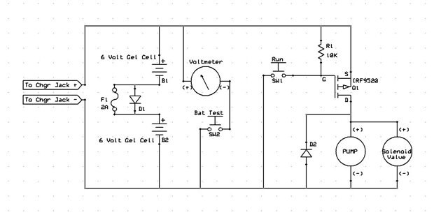
Here is a schematic of the project:


image


I began the project by collecting a variety of potential components. My Goal was to draw her thickened water from a reservoir and pump it up a line and into her mouth. She is accustomed to using a push button call switch when she needs help from an attendant so I decided to use a very similar switch to actuate the pump.


The water line would run axially with the switch and its wiring. The switch could be held in her hand and the water feed line would continue past the switch by about 4 inches.


image

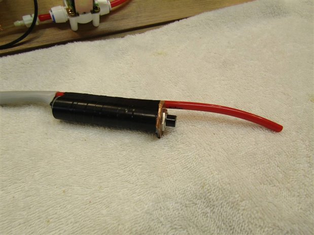
Picture of Hand Switch


I decided to try a small 12 volt water pump, that is usually used in small fountains, to pump the water from the reservoir.


image

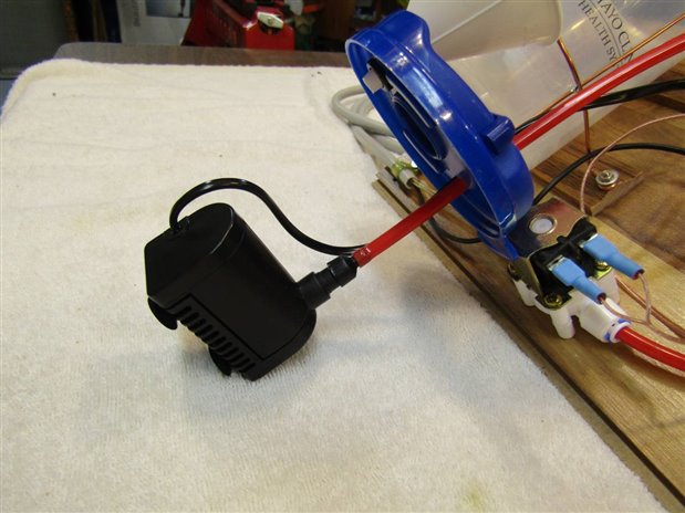
Picture of Pump in the Reservoir


My first prototype did not include an in line solenoid. This created a problem if the cord accidentally fell to the floor as gravity would siphon the water from the reservoir and create a big mess on the floor. My final prototype needed a solenoid.


image

Solenoid Picture


Since space and weight were not a particular problem I decided to use two 6 volt 4.5 Ahr Lead Acid Gel Cells for the batteries.
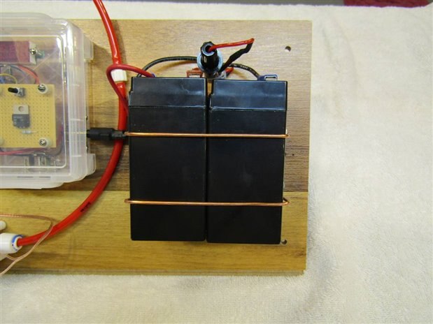
 

image

Battery Picture


A small Volt Meter circuit was incorporated in the control box so I could check the level of the battery and recharge it when needed.
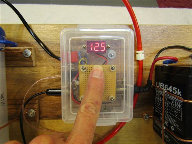
 

image

Control Box Picture


The control box is very simple with the Volt Meter and a momentary switch to activate it, a single P Channel MOSFET, Jacks for: Batteries, Charger, Pump, Solenoid, and actuation switch.


    imageimage

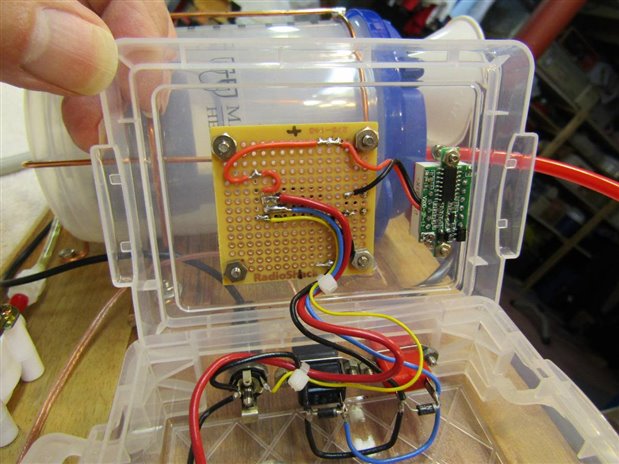
Pictures on inside the Control Box


The Reservoir is an lightly insulated hospital drinking cup that I brought home after a past overnight adventure.


image

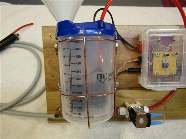
Picture of the Reservoir.


Here is a picture of the finished project before I took it to Mom's room and nylon strapped it to the back of her wheel chair.


image

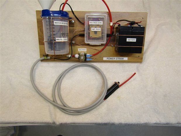
Picture of completed assembly


I can see room for many improvements. The parts that I ordered and received did not meet my imagined specifications. For example the pump could have a little more power and the solenoid draws too much current. While the batteries will be heavy enough to deal with the present solenoid, ideally, I should be able to find one that uses 200 mA or less instead of the current 400+ mA. I have made the reservoir and hand cord easy to disassemble for cleaning but improvements can be made. The plugs that were used on the pump and the solenoid were not polarized. While this will not affect the solenoid it is important the the pump spin in the correct direction for maximum efficiency. I have marked the non-polarized plugs but someone other than me might miss this detail. For the time being however Mom is happy and after the newness wears off she too will have some good suggestions for her sonny boy on how he can make it better.

  • Sign in to reply

Top Comments

  • dougw
    dougw over 9 years ago +6
    They say need is the mother of invention, mothers are also the mothers of invention. Very nicely done John. If you are looking for improvement ideas, you might consider using a peristaltic pump - the liquid…
  • jw0752
    jw0752 over 9 years ago +6
    Here is the next iteration of the prototype using a peristaltic pump. The first thing to note is that the reservoir holder has been changed so that it will accommodate the standard drinking cup that is…
  • jw0752
    jw0752 over 9 years ago +5
    ERRATA : I have discovered that I made a mistake and published incorrect information reference the mA draw of the peristaltic pump. If one looks closely at the picture of the Fluke Meter in my last post…
Parents
  • jw0752
    jw0752 over 9 years ago

    Here is the next iteration of the prototype using a peristaltic pump.


    image

    The first thing to note is that the reservoir holder has been changed so that it will accommodate the standard drinking cup that is used in Mom's nursing home. Rather than messing with pouring the thickened water that she has to drink into a separate reservoir all the staff has to do is replace one cup with another and insert the red hose into the straw hole. I mentioned thickened water. I never realized this but if one is not able to swallow properly water of regular consistency can pose a greater danger of choking. For this reason they give Mom a special thickened water that is easier to swallow.


    Here is a detail picture of the cup holder:


    image


    The red hose from the cup goes to the inlet of the peristaltic pump. The pump itself is controlled by a variable pulse width modulation generator in the control box. I was very pleased with the small peristaltic pump as it is capable of moving 75 milliliter of the thickened water per minute when the pump is running at 12 volts. Since the control box (See Red Capped Knob on top of the control) allows me to control the PWM 0% to 100% I can reduce the output of the pump as needed so as not to over run Mom's ability to swallow. Here is a detail of the peristaltic pump and the manifold that I built to interface with the feed from the cup and the line to drinking tube.


    image


    image


    One of the very pleasant surprises was that the peristaltic pump only drew 32  mA at the full 100 % PMW level. This is more than a magnitude reduction from the 500 mA + current needed for the first prototype. Current calculations suggest that the battery should be able to run the unit for a couple weeks at a time without recharging.  Since the Peristaltic pump pinches the line continuously there is also no need for a solenoid to prevent siphoning. Check out the ammeter reading for the pump.


    image


    For the fun of it I made a video of the pump in action. Check it out.


    You don't have permission to edit metadata of this video.
    Edit media
    x
    image
    Upload Preview
    image


    The unit is now back attached to Mom's wheel chair and she has been using it for a day. We will be watching for other problems and opportunities to improve it in the coming days.


    John

    • Cancel
    • Vote Up +6 Vote Down
    • Sign in to reply
    • More
    • Cancel
  • ntewinkel
    ntewinkel over 9 years ago in reply to jw0752

    You are really inspiring, John!


    I love that you built this to help your mom, and I love that you shared the details with us.


    Also, your build is nice and clean - something I definitely need to work on in my projects image


    Now, tell me about the wooden robot in the top picture of the "next iteration prototype" image


    Cheers,

    -Nico

    • Cancel
    • Vote Up +3 Vote Down
    • Sign in to reply
    • More
    • Cancel
  • Jan Cumps
    Jan Cumps over 9 years ago in reply to jw0752

    John, is it possible to feed the pump the full 12V until it's 'primed'?

    a possible setup may be to draw the MOSFET into conduction for a given short amount of time, using an RC circuit. And then handing over control to the 555's output?


    that would give the pump an aggressive kick of power for a brief moment, and have it moving.


    An RC circuit, with a Schmitt trigger, could pull the FET into saturation just for a short pulse ( a kick in the butt), and then the more moderate signal of the 555 can deliver a smooth moderate pump activity.


    you could put an OR gate in place (two diodes image ) to combine the two signals at the gate....

    • Cancel
    • Vote Up +3 Vote Down
    • Sign in to reply
    • More
    • Cancel
  • jw0752
    jw0752 over 9 years ago in reply to Jan Cumps

    Hi Jan,

    I really like your idea to start the pump with a 1 or 2 second full power boost. From your good description you have done all the hard work for me already. Tonight I will start the fun part and try to breadboard the circuit that you described.

    John


    I will tell Mom today about all the help I am getting designing her drinking machine from engineers all over the world. She will get a kick out of that.

    • Cancel
    • Vote Up +3 Vote Down
    • Sign in to reply
    • More
    • Cancel
  • Jan Cumps
    Jan Cumps over 9 years ago in reply to jw0752

    Say Hi to Mom, and good luck with the experiment.

    • Cancel
    • Vote Up +1 Vote Down
    • Sign in to reply
    • More
    • Cancel
  • shabaz
    shabaz over 9 years ago in reply to jw0752

    Hi John,


    The method Jan suggests is fairly essential to get it to operate at low speeds. There is also a general way of doing it, but it is awkward. The problem with PWM on its own is (as can be seen) the lack of torque at low speeds. If the peristaltic pump is hackable then the motor could be replaced with a stepper motor but then a controller for that is needed/ Another way is to get some feedback off the motor shaft (before it is geared down) so you can feed it into a servo controller type circuit where the pulses off the shaft will be compared with a set value from your potentiometer. This could be achieved maybe by using bits from hobby servo motors, but again will be difficult. If you do see a way of getting pulses from the shaft (e.g. attaching a magnet) then something like MC33030 or MC33033 (it is actually intended for brushless operation but it can be used in a brushed motor mode) would work, but the trouble is they are obsolete. I do have a board I made with a MC33033 on it, and the board could be repurposed for your project. Let me know if you want to pursue that method, and I'll get it sent across. It will require fiddling with R and C values to get the pulses from the shaft sensor to a suitable form for comparing with the potentiometer setting, etc.

    Alternatively a microcontroller could be used, to detect when the shaft is not rotating (from the magnet and a digital output hall sensor) and increase the pulse width to get it moving again. That might be the easiest to be honest. If you want to go that route, I'd suggest a FRDM-KL25Z board and I can help you with the software. This method would just require the shaft magnet/sensor, and a FET for your motor which you already have in the circuit anyway, provided it can be switched from 3.3V which is what the FRDM-KL25Z output will be. The PWM can be implemented in software in the KL25Z board, and it has an analog input for the adjustment potentiometer too. Basically with all these methods, the closed-loop feedback from the sensor will always ensure that the motor is never stalled even at slow speeds.

    • Cancel
    • Vote Up 0 Vote Down
    • Sign in to reply
    • More
    • Cancel
  • dougw
    dougw over 9 years ago in reply to jw0752

    A P-channel FET between the positive rail and the gate of Q2 could work.

    The gate of this FET would have a 1M pull-up to the rail and a 1uf cap to ground.

    The gate of Q1 will be high until the capacitor charges up, then the new FET is dormant.

    • Cancel
    • Vote Up 0 Vote Down
    • Sign in to reply
    • More
    • Cancel
Comment
  • dougw
    dougw over 9 years ago in reply to jw0752

    A P-channel FET between the positive rail and the gate of Q2 could work.

    The gate of this FET would have a 1M pull-up to the rail and a 1uf cap to ground.

    The gate of Q1 will be high until the capacitor charges up, then the new FET is dormant.

    • Cancel
    • Vote Up 0 Vote Down
    • Sign in to reply
    • More
    • Cancel
Children
No Data
element14 Community

element14 is the first online community specifically for engineers. Connect with your peers and get expert answers to your questions.

  • Members
  • Learn
  • Technologies
  • Challenges & Projects
  • Products
  • Store
  • About Us
  • Feedback & Support
  • FAQs
  • Terms of Use
  • Privacy Policy
  • Legal and Copyright Notices
  • Sitemap
  • Cookies

An Avnet Company © 2026 Premier Farnell Limited. All Rights Reserved.

Premier Farnell Ltd, registered in England and Wales (no 00876412), registered office: Farnell House, Forge Lane, Leeds LS12 2NE.

ICP 备案号 10220084.

Follow element14

  • X
  • Facebook
  • linkedin
  • YouTube