element14 Community
element14 Community
    Register Log In
  • Site
  • Search
  • Log In Register
  • Community Hub
    Community Hub
    • What's New on element14
    • Feedback and Support
    • Benefits of Membership
    • Personal Blogs
    • Members Area
    • Achievement Levels
  • Learn
    Learn
    • Ask an Expert
    • eBooks
    • element14 presents
    • Learning Center
    • Tech Spotlight
    • STEM Academy
    • Webinars, Training and Events
    • Learning Groups
  • Technologies
    Technologies
    • 3D Printing
    • FPGA
    • Industrial Automation
    • Internet of Things
    • Power & Energy
    • Sensors
    • Technology Groups
  • Challenges & Projects
    Challenges & Projects
    • Design Challenges
    • element14 presents Projects
    • Project14
    • Arduino Projects
    • Raspberry Pi Projects
    • Project Groups
  • Products
    Products
    • Arduino
    • Avnet Boards Community
    • Dev Tools
    • Manufacturers
    • Multicomp Pro
    • Product Groups
    • Raspberry Pi
    • RoadTests & Reviews
  • About Us
  • Store
    Store
    • Visit Your Store
    • Choose another store...
      • Europe
      •  Austria (German)
      •  Belgium (Dutch, French)
      •  Bulgaria (Bulgarian)
      •  Czech Republic (Czech)
      •  Denmark (Danish)
      •  Estonia (Estonian)
      •  Finland (Finnish)
      •  France (French)
      •  Germany (German)
      •  Hungary (Hungarian)
      •  Ireland
      •  Israel
      •  Italy (Italian)
      •  Latvia (Latvian)
      •  
      •  Lithuania (Lithuanian)
      •  Netherlands (Dutch)
      •  Norway (Norwegian)
      •  Poland (Polish)
      •  Portugal (Portuguese)
      •  Romania (Romanian)
      •  Russia (Russian)
      •  Slovakia (Slovak)
      •  Slovenia (Slovenian)
      •  Spain (Spanish)
      •  Sweden (Swedish)
      •  Switzerland(German, French)
      •  Turkey (Turkish)
      •  United Kingdom
      • Asia Pacific
      •  Australia
      •  China
      •  Hong Kong
      •  India
      •  Korea (Korean)
      •  Malaysia
      •  New Zealand
      •  Philippines
      •  Singapore
      •  Taiwan
      •  Thailand (Thai)
      • Americas
      •  Brazil (Portuguese)
      •  Canada
      •  Mexico (Spanish)
      •  United States
      Can't find the country/region you're looking for? Visit our export site or find a local distributor.
  • Translate
  • Profile
  • Settings
Arduino
  • Products
  • More
Arduino
Arduino Forum Arduino and Transistors Question - RE: School Musical Production
  • Blog
  • Forum
  • Documents
  • Quiz
  • Events
  • Polls
  • Files
  • Members
  • Mentions
  • Sub-Groups
  • Tags
  • More
  • Cancel
  • New
Join Arduino to participate - click to join for free!
Actions
  • Share
  • More
  • Cancel
Forum Thread Details
  • State Verified Answer
  • Replies 126 replies
  • Answers 2 answers
  • Subscribers 402 subscribers
  • Views 7520 views
  • Users 0 members are here
  • raspberry
  • transistor
  • pi
  • arduino
Related

Arduino and Transistors Question - RE: School Musical Production

wallarug
wallarug over 11 years ago

One of the directors has asked me to create a special backdrop for our college musical. This particular backdrop has a particular design (see below) that includes LED strip lighting to give the feel of a 1920s casino sign – similar to what is seen today in Las Vegas.

I  have done up a detailed design for this sign, based off the rough sketch given to me by the director and the dimensions of the backdrop.  On this diagram, the arrangement of the LED strip lighting can be seen.

image


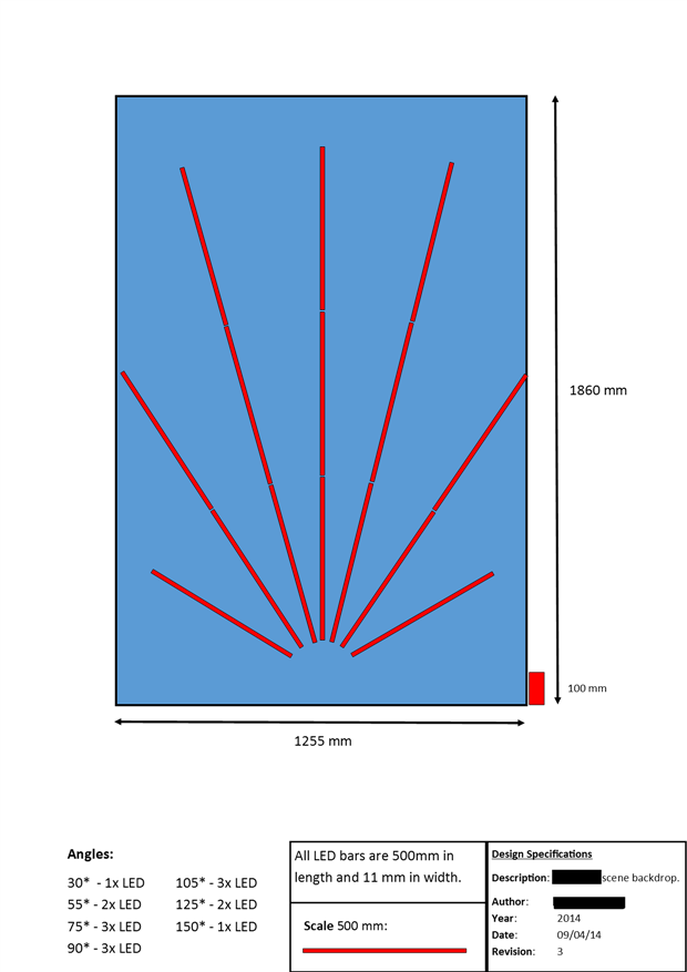
The LED Strip lighting that will be bought for this project will be sourced from Jaycar – “Low Cost 5m Flexible Adhesive LED Strip Light – Warm White” (ZD0577).  According to the specifications off Jaycar’s website, these LED lights need 1.1 Amps per metre @ 12 volts.  This means that the longest segments of lights need 1.1 * 1.5 = 1.65 Amps of power (rounded up by 20% for safety: 2.0 Amps @ 12 volts).


This would not be an issue if I was just turning these LED Strips on and off with mains power BUT I want to control these LEDs via an Arduino, so that they can do fancy things like flash and chase.  That means that I would need a circuit to control these lights with an Arduino so that everything remains safe and does not blow up.

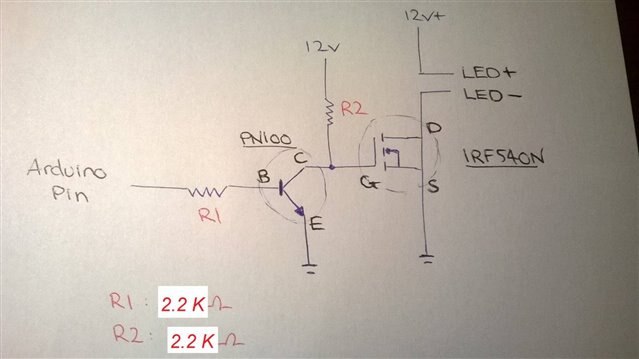
I have come up with this circuit (below) using a couple of NPN transistors and two power supplies.  In the diagram below, I am aware that the transistor pinouts are EBC.  The ones I am going to buy have a pinout of BCE.


image


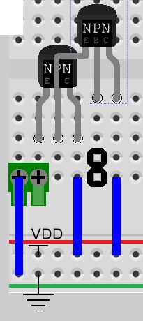
The only problem with this is that I have very little understanding of transistor circuits.  What this circuit has to be able to do is:

  • Using the smallest amount of current from the Arduino (at 5 volts) or a Raspberry Pi (3v3 volts), turn on the circuit to allow the 12 volts that powers the LED strip lighting to flow.


I was thinking of using either TIP41C NPN Transistors (in a darlington Array) or TIP122 NPN transistors.


This circuit will be replicated 8 times over to accommodate for the number of LEDs I am controlling.


Can anyone help me:

  1. Design a circuit that will work 100% and will be safe (ie: low heat)
    1. This includes base resistance
  1. Confirm which transistors I should be using for this project.


Any help will be much appreciated.

  • Sign in to reply
  • Cancel

Top Replies

  • Robert Peter Oakes
    Robert Peter Oakes over 11 years ago +1
    Sorry the one I suggested wont work, but this one should http://www.jaycar.com.au/productView.asp?ID=ZK8821 10+ current rating and at 0.016ohms it should be good for your needs pdf here http://www.vishay…
  • mcb1
    mcb1 over 11 years ago in reply to jw0752 +1
    John If you are referring to this It means that at a gate voltage of 1.6 typ, a current of 250uA will be flowing in the Drain. If you look here, you can see that from 3 to 3.3v will give you enough to…
  • D_Hersey
    D_Hersey over 11 years ago +1
    Solenoid Whapper:
Parents
  • wallarug
    0 wallarug over 11 years ago

    Hey guys!


    I have built one sample circuit on the PCB but I have an issue.


    When the wire coming from the Arduino (pin 9) registers 4.95v when it is NOT connected to the board.  When that same wire is connected to my circuit board, it registers 0.9v (from pin 9).


    Any ideas what is causing this?  When I built the exact (when I say exact I mean EXACTLY THE SAME) same circuit on the breadboard it works perfectly.


    I am missing something?

    • Cancel
    • Vote Up 0 Vote Down
    • Sign in to reply
    • Verify Answer
    • Cancel
  • gihu
    0 gihu over 11 years ago in reply to wallarug

    If you are using the transistor... Maybe you missed the resistor between the arduino output the base of the transistor?


    Hope that helps,

    Miguel

    • Cancel
    • Vote Up 0 Vote Down
    • Sign in to reply
    • Verify Answer
    • Cancel
  • wallarug
    0 wallarug over 11 years ago in reply to gihu

    i don't have that part installed - correct.


    But that is not the issue because I did not have that installed on the Breadboard.


    I think the FET might have died but I am still testing.

    • Cancel
    • Vote Up 0 Vote Down
    • Sign in to reply
    • Verify Answer
    • Cancel
  • mcb1
    0 mcb1 over 11 years ago in reply to gihu

    wallrug

    Can we presume that you have made the cct based on this


    image


    okay ...seriously you need to add a resistor between the Arduino pin and the PN100.

    The 0.93 v you are measuring is because the Arduino is trying its hardest to ram 5v down the base junction of the PN100.


    image


    Luckily the Aduino will limit the current to 40mA ...so at least it isn't destroyed.


    Once you've done that you might find your PN100 starts behaving properly.


    Mark

    • Cancel
    • Vote Up 0 Vote Down
    • Sign in to reply
    • Verify Answer
    • Cancel
  • wallarug
    0 wallarug over 11 years ago in reply to mcb1

    Just to clarify this is what I have:


    Working (breadboard):

    image


    Not working (referred to as: PCB):

    image

    Underside:

    image


    Green Circle is where FET comes out.


    Testing conducted on PCB:

    1. voltage from Arduino to NPN base: 0.9v

    2. voltage from resistor: 4.95v (1) - 0v (0)

    3. voltage out of going into FET gate: 4.95v (1) - 0v (0)

    4. voltage out of FET Drain: 0.02v (0) - 0v (1)


    Any ideas?

    • Cancel
    • Vote Up 0 Vote Down
    • Sign in to reply
    • Verify Answer
    • Cancel
Reply
  • wallarug
    0 wallarug over 11 years ago in reply to mcb1

    Just to clarify this is what I have:


    Working (breadboard):

    image


    Not working (referred to as: PCB):

    image

    Underside:

    image


    Green Circle is where FET comes out.


    Testing conducted on PCB:

    1. voltage from Arduino to NPN base: 0.9v

    2. voltage from resistor: 4.95v (1) - 0v (0)

    3. voltage out of going into FET gate: 4.95v (1) - 0v (0)

    4. voltage out of FET Drain: 0.02v (0) - 0v (1)


    Any ideas?

    • Cancel
    • Vote Up 0 Vote Down
    • Sign in to reply
    • Verify Answer
    • Cancel
Children
  • wallarug
    0 wallarug over 11 years ago in reply to wallarug

    More content (a video showing that it works on breadboard):

    Youtube link: MOSFET / NPN Circuit working on Breadboard - YouTube


    • Cancel
    • Vote Up 0 Vote Down
    • Sign in to reply
    • Verify Answer
    • Cancel
  • dougw
    0 dougw over 11 years ago in reply to wallarug

    It looks like the PN100 emitter on the breadboard is not connected to anything. It looks like the green wire is connected to the base. Is this correct? (if the emitter is not grounded the base could be driven high)

    As MCB points out, the NPN PN100 really should have a resistor connected between the base and the arduino because the voltage between base and emitter can not exceed 1  forward diode drop (1 volt according to the datasheet).

    • Cancel
    • Vote Up 0 Vote Down
    • Sign in to reply
    • Verify Answer
    • Cancel
  • wallarug
    0 wallarug over 11 years ago in reply to dougw

    just to clarify: the base is NOT connected to anything and the emitter is grounded (as per the schematic posted with the pn100.
    The collector is connect to the resistor (r2 - goes to 5v/12v). On the same line is the gate of the mosfet.

    the two blue screw terminals are the led breaks that can be seen in the schematic. The one furthest from the mosfet is connect straight to the 5v/12v rail. The other half of the blue connector goes into the mosfet drain. The mosfet source goes to ground.


    That should be the same in both circuits.

    • Cancel
    • Vote Up 0 Vote Down
    • Sign in to reply
    • Verify Answer
    • Cancel
  • Robert Peter Oakes
    0 Robert Peter Oakes over 11 years ago in reply to wallarug

    in the diagram above the base of the transistor is clearly connected to R1 and then the other side of R1 is connected to the Arduino output pin


    You need to connect this up for you circuit to work

    • Cancel
    • Vote Up 0 Vote Down
    • Sign in to reply
    • Verify Answer
    • Cancel
  • mcb1
    0 mcb1 over 11 years ago in reply to Robert Peter Oakes

    Wallrug


    You may also need to pay attention for dry joints in the final part of this (after you add the base resistor)

    These suggest poor contact with the connector.


    image


    Your post is very interesting, as I wasn't aware those types of prototype board exist.


    For future reference, if you swap the PN100 down to the 'c' row, and place the FET at 'e' row, you could have room for a heatsink.

    I always prefer to have them with the metal bit away from the electronics (ie rotated 180 deg), because one day you'll be measuring/adding a wire to the connector when the power is on.....

    Then that No5 answer appears   As long as nothing is damaged/destroyed or otherwise had the magic smoke let out.


    Mark

    edit fixed spelling mistake

    • Cancel
    • Vote Up 0 Vote Down
    • Sign in to reply
    • Verify Answer
    • Cancel
  • Problemchild
    0 Problemchild over 11 years ago in reply to mcb1

    Yes Mark those PCBs are quite common I even found some in the Farnell catalogue (did come from Adafruit though!!)


    http://uk.farnell.com/mcu-mpu-dsc-dsp-fpga-development-kits_accessories/accessory-type/breadboard-pcb-kit/pg/110514094

    • Cancel
    • Vote Up 0 Vote Down
    • Sign in to reply
    • Verify Answer
    • Cancel
  • Problemchild
    0 Problemchild over 11 years ago in reply to wallarug

    Sorry there I don't to Labour it but really  you need to check over that soldering and clean up all those joins  several have far too much solder and several barely any at all and this may just be the problem any number of bad joints would cause your problem


    John

    • Cancel
    • Vote Up 0 Vote Down
    • Sign in to reply
    • Verify Answer
    • Cancel
  • mcb1
    0 mcb1 over 11 years ago in reply to Problemchild

    John

    Thanks for the link .. the small one is for the RPi 'extender' although I used a different type.


    mark

    • Cancel
    • Vote Up 0 Vote Down
    • Sign in to reply
    • Verify Answer
    • Cancel
  • wallarug
    0 wallarug over 11 years ago in reply to Problemchild

    I will let the builder know that his work is not up to standard.

    • Cancel
    • Vote Up 0 Vote Down
    • Sign in to reply
    • Verify Answer
    • Cancel
  • Problemchild
    0 Problemchild over 11 years ago in reply to wallarug

    Sorry Wallarug wasn't trying to be awful but  bad construction techniques will simply drive you round the twist and if you've copied the breadboard exactly you will be chasing your self until you get past these bits .

    • Cancel
    • Vote Up 0 Vote Down
    • Sign in to reply
    • Verify Answer
    • Cancel
element14 Community

element14 is the first online community specifically for engineers. Connect with your peers and get expert answers to your questions.

  • Members
  • Learn
  • Technologies
  • Challenges & Projects
  • Products
  • Store
  • About Us
  • Feedback & Support
  • FAQs
  • Terms of Use
  • Privacy Policy
  • Legal and Copyright Notices
  • Sitemap
  • Cookies

An Avnet Company © 2025 Premier Farnell Limited. All Rights Reserved.

Premier Farnell Ltd, registered in England and Wales (no 00876412), registered office: Farnell House, Forge Lane, Leeds LS12 2NE.

ICP 备案号 10220084.

Follow element14

  • X
  • Facebook
  • linkedin
  • YouTube