element14 Community
element14 Community
    Register Log In
  • Site
  • Search
  • Log In Register
  • Community Hub
    Community Hub
    • What's New on element14
    • Feedback and Support
    • Benefits of Membership
    • Personal Blogs
    • Members Area
    • Achievement Levels
  • Learn
    Learn
    • Ask an Expert
    • eBooks
    • element14 presents
    • Learning Center
    • Tech Spotlight
    • STEM Academy
    • Webinars, Training and Events
    • Learning Groups
  • Technologies
    Technologies
    • 3D Printing
    • FPGA
    • Industrial Automation
    • Internet of Things
    • Power & Energy
    • Sensors
    • Technology Groups
  • Challenges & Projects
    Challenges & Projects
    • Design Challenges
    • element14 presents Projects
    • Project14
    • Arduino Projects
    • Raspberry Pi Projects
    • Project Groups
  • Products
    Products
    • Arduino
    • Avnet & Tria Boards Community
    • Dev Tools
    • Manufacturers
    • Multicomp Pro
    • Product Groups
    • Raspberry Pi
    • RoadTests & Reviews
  • About Us
  • Store
    Store
    • Visit Your Store
    • Choose another store...
      • Europe
      •  Austria (German)
      •  Belgium (Dutch, French)
      •  Bulgaria (Bulgarian)
      •  Czech Republic (Czech)
      •  Denmark (Danish)
      •  Estonia (Estonian)
      •  Finland (Finnish)
      •  France (French)
      •  Germany (German)
      •  Hungary (Hungarian)
      •  Ireland
      •  Israel
      •  Italy (Italian)
      •  Latvia (Latvian)
      •  
      •  Lithuania (Lithuanian)
      •  Netherlands (Dutch)
      •  Norway (Norwegian)
      •  Poland (Polish)
      •  Portugal (Portuguese)
      •  Romania (Romanian)
      •  Russia (Russian)
      •  Slovakia (Slovak)
      •  Slovenia (Slovenian)
      •  Spain (Spanish)
      •  Sweden (Swedish)
      •  Switzerland(German, French)
      •  Turkey (Turkish)
      •  United Kingdom
      • Asia Pacific
      •  Australia
      •  China
      •  Hong Kong
      •  India
      •  Korea (Korean)
      •  Malaysia
      •  New Zealand
      •  Philippines
      •  Singapore
      •  Taiwan
      •  Thailand (Thai)
      • Americas
      •  Brazil (Portuguese)
      •  Canada
      •  Mexico (Spanish)
      •  United States
      Can't find the country/region you're looking for? Visit our export site or find a local distributor.
  • Translate
  • Profile
  • Settings
Arduino
  • Products
  • More
Arduino
Arduino Forum Best practices for Arduino I/O selection
  • Blog
  • Forum
  • Documents
  • Quiz
  • Events
  • Polls
  • Files
  • Members
  • Mentions
  • Sub-Groups
  • Tags
  • More
  • Cancel
  • New
Join Arduino to participate - click to join for free!
Actions
  • Share
  • More
  • Cancel
Forum Thread Details
  • Replies 19 replies
  • Subscribers 395 subscribers
  • Views 4273 views
  • Users 0 members are here
  • arduino_development_environment
  • arduino
Related

Best practices for Arduino I/O selection

colporteur
colporteur over 3 years ago

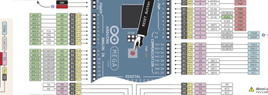
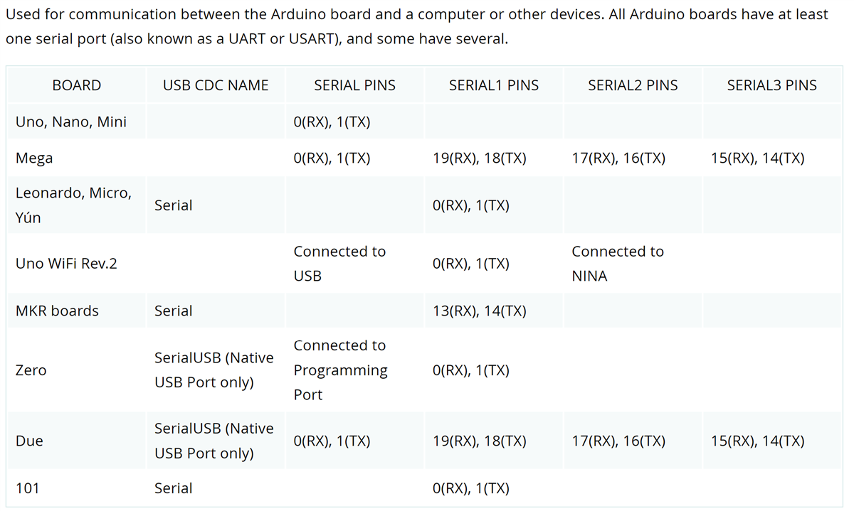
I'm currently working on a project using an Arduino knock-off Mega board. I discovered during prototype board development and testing an issue using I/O' 0 and 1. I found I could not control the output within my script. From online research, I discovered if I was using serial communication then I should avoid using those two I/O's. I wonder what other gotcha's don't know about?

I confess I am way down the scale of Arduinos knowledge. I label myself more of a resurrectionist rather than a programmer. I adapt code and solutions I find to solve my problems. Rarely if ever, have I built from scratch. This leads me to the title line "Best Practices for Arduino I/O selection". Are there any resources that provide this type of guidance? Are there I/O's to avoid and others that are better for a specific function?

I realize some I/O's are for specific purposes. I'm just thinking are there best practices using I/O's. I read the review posted on the site of this new book and thought maybe that has some suggestions. I'm looking for member experience.

  • Sign in to reply
  • Cancel

Top Replies

  • Jan Cumps
    Jan Cumps over 3 years ago in reply to shabaz +7
    I use the same principles but the other way round. I first do the inflexible ones, like UART, i2c/SPI, pwm/timer , interrupt and analogue. Then sprinkle the easy ones across what's left over.
  • fmilburn
    fmilburn over 3 years ago +7
    I've been caught out with this type of problem when using the Arduino IDE with a board I'm unfamiliar with so I can relate. In your case, the pins with the labels 0 and 1 on the silkscreen will cause a…
  • shabaz
    shabaz over 3 years ago +5
    Hi Sean, The usual board pinout diagrams often indicate all functions available per pin, so they can be used for guidance, but the ultimate authority is the chip datasheet. Example snippet (found via…
  • shabaz
    shabaz over 3 years ago

    Hi Sean,

    The usual board pinout diagrams often indicate all functions available per pin, so they can be used for guidance, but the ultimate authority is the chip datasheet.

    Example snippet (found via google images):

    image


    From my perspective (others may do it differently), the way I go about it is, to decide which connections in my circuit are the simplest (e.g. basic outputs like binary status LEDs) and assign them to the least flexible GPIO pins on the chip (using the usual board pinout diagrams, or the datasheet). Then, I'll look at the board-level serial interfaces (e.g. SPI, I2C) and choose pins that support those functions, but again the least flexible ones from all other perspectives, e.g. if one set of I2C pins also supports UART, then I will likely not select those I2C pins. For buttons I'll likely try to select pins that can work as interrupt inputs, if I just have a couple of buttons or so. For encoders, again interrupt-supporting pins are important/highly useful.


    And so on, working my way through all the pins, and hopefully as a result, ending up with spare pins which have a lot of functions still available. They can go to a future expansion connector if desired. Sometimes a slight second iteration is needed when laying out the board, to simplify some track paths.


    This strategy game of selecting pins is becoming less important with some recent processors, they are more orthogonal in that selecting one pin won't shut off the option of using integrated peripherals on another pin, it's a lot more configurable basically. The Pi Pico is an example kind-of approaching that (not entirely), where there is a fair amount of flexibility, one main exception is that analog inputs are still dedicated to particular pins. 

    • Cancel
    • Vote Up +5 Vote Down
    • Sign in to reply
    • Cancel
  • beacon_dave
    beacon_dave over 3 years ago

    On the Arduino Mega the first UART is wired to the 16U2 which connects you via USB to the host computer.

     image

    https://docs.arduino.cc/static/90b1ec517675fa8610166a1199868f51/A000067-datasheet.pdf

    The full pinout gives an overview of what the various pins are shared with
    https://docs.arduino.cc/static/edb006e0a180e80b9ea9cf8b4859dcd4/A000067-full-pinout.pdf

    Not all pins have PWM so perhaps one to watch out for and only a subset of the digital I/O are connected to the analogue multiplexer.

    Arduino uses some of the on-chip timers so need to be careful there
    Timer 0 - delay(), millis(), micros()
    Timer 1 - servo library
    Timer 2 - tone library
    /products/arduino/f/forum/39162/how-do-you-know-what-resources-timers-and-such-are-being-used-in-a-sketch

    Arduino hardware resource map
    https://code.google.com/archive/p/arduino/wikis/HardwareResourceMap.wiki

    • Cancel
    • Vote Up +4 Vote Down
    • Sign in to reply
    • Cancel
  • Jan Cumps
    Jan Cumps over 3 years ago in reply to shabaz

    I use the same principles but the other way round. I first do the inflexible ones, like UART, i2c/SPI, pwm/timer , interrupt and analogue. Then sprinkle the easy ones across what's left over.

    • Cancel
    • Vote Up +7 Vote Down
    • Sign in to reply
    • Cancel
  • shabaz
    shabaz over 3 years ago in reply to Jan Cumps

    Ahh.. That would work too! : )

    • Cancel
    • Vote Up 0 Vote Down
    • Sign in to reply
    • Cancel
  • shabaz
    shabaz over 3 years ago in reply to beacon_dave

    Good reminder.. software libraries can matter as you say, and sometimes they are coded or tested more on some pins too! even if theoretically they should work : ) All a balancing act factoring all that in, as well as any future project modification aspirations, e.g. swapping out a display to a different one, is easier if both displays/libraries of code are considered and so on.

    • Cancel
    • Vote Up +2 Vote Down
    • Sign in to reply
    • Cancel
  • Jan Cumps
    Jan Cumps over 3 years ago in reply to beacon_dave

    Yes. Libraries can restrict your options. And other shields you are using in your design may also reserve pins.

    • Cancel
    • Vote Up +2 Vote Down
    • Sign in to reply
    • Cancel
  • colporteur
    colporteur over 3 years ago in reply to beacon_dave

    Your posts reflect your level of experience, which I envy. I'm in the category of I don't know what I don't know. I wasn't aware of the D0  & D1 caveat. I will remember that in the future. Your Timer details give me the reason for the pause.

    Without guidance mapping, I/O seems hit and miss.

    • Cancel
    • Vote Up +2 Vote Down
    • Sign in to reply
    • Cancel
  • Jan Cumps
    Jan Cumps over 3 years ago in reply to colporteur

    It's not a hit and miss, because the info is available for most Arduino's, shields and libraries.
    But it is a practice that's unavoidable when doing micro-electronics and electronics: there is planning and investigation required.

    • Cancel
    • Vote Up +2 Vote Down
    • Sign in to reply
    • Cancel
  • fmilburn
    fmilburn over 3 years ago

    I've been caught out with this type of problem when using the Arduino IDE with a board I'm unfamiliar with so I can relate. In your case, the pins with the labels 0 and 1 on the silkscreen will cause a conflict since they also have RX and TX beside them which are used for the serial terminal.  The Arduino reference documentation (as well as the material Dave linked) covers this as shown in the excerpt below.

    image

    But even here they don't state that pins 18 and 19 are set up using Serial1 as opposed to plain Serial for pins 0 and 1.  For that you have to look in the Serial.begin() documentation and it is also shown on the silkscreen.  So the information is spread about.

    The Arduino documentation is pretty good about specifying these things for the Uno in the documentation but the further you stray from that model the less likely that is to be so.  There are so many different processors that use the IDE now (many not even developed by Arduino) it isn't possible to cover them all in one place and it is necessary to pay close attention to the board pinout.  By the time you get to some of the Espressif boards, all bets are off.  Some of the silkscreens are awful and there is only generic information at best.

    The sources that beacon_dave gives are as good as any I know of along with the documentation in the Arduino reference.  But it is hard to avoid unexpected issues and use of google, especially when using a new board.  Boards with daughterboards/shields having sensors, screens, buttons, and such are often problems as they take away pins.

    • Cancel
    • Vote Up +7 Vote Down
    • Sign in to reply
    • Cancel
  • dougw
    dougw over 3 years ago

    I always create a spreadsheet listing all the MCU pins and their possible functions, then I add peripherals or chips and all their pins opposite the MCU pins they will be connected to.

    There is an example here that provides an idea of what I do:

    /challenges-projects/design-challenges/sixth-sense-design-challenge/b/blog/posts/sixth-sense---interfaces---graffitibot-blog-4

    It might be  a bit confusing because the Nucleo has its native headers connected to Arduino headers, but this is a good reason to track it in a spreadsheet.

    • Cancel
    • Vote Up +2 Vote Down
    • Sign in to reply
    • Cancel
>
element14 Community

element14 is the first online community specifically for engineers. Connect with your peers and get expert answers to your questions.

  • Members
  • Learn
  • Technologies
  • Challenges & Projects
  • Products
  • Store
  • About Us
  • Feedback & Support
  • FAQs
  • Terms of Use
  • Privacy Policy
  • Legal and Copyright Notices
  • Sitemap
  • Cookies

An Avnet Company © 2025 Premier Farnell Limited. All Rights Reserved.

Premier Farnell Ltd, registered in England and Wales (no 00876412), registered office: Farnell House, Forge Lane, Leeds LS12 2NE.

ICP 备案号 10220084.

Follow element14

  • X
  • Facebook
  • linkedin
  • YouTube