element14 Community
element14 Community
    Register Log In
  • Site
  • Search
  • Log In Register
  • About Us
  • Community Hub
    Community Hub
    • What's New on element14
    • Feedback and Support
    • Benefits of Membership
    • Personal Blogs
    • Members Area
    • Achievement Levels
  • Learn
    Learn
    • Ask an Expert
    • eBooks
    • element14 presents
    • Learning Center
    • Tech Spotlight
    • STEM Academy
    • Webinars, Training and Events
    • Learning Groups
  • Technologies
    Technologies
    • 3D Printing
    • FPGA
    • Industrial Automation
    • Internet of Things
    • Power & Energy
    • Sensors
    • Technology Groups
  • Challenges & Projects
    Challenges & Projects
    • Design Challenges
    • element14 presents Projects
    • Project14
    • Arduino Projects
    • Raspberry Pi Projects
    • Project Groups
  • Products
    Products
    • Arduino
    • Avnet Boards Community
    • Dev Tools
    • Manufacturers
    • Multicomp Pro
    • Product Groups
    • Raspberry Pi
    • RoadTests & Reviews
  • Store
    Store
    • Visit Your Store
    • Choose another store...
      • Europe
      •  Austria (German)
      •  Belgium (Dutch, French)
      •  Bulgaria (Bulgarian)
      •  Czech Republic (Czech)
      •  Denmark (Danish)
      •  Estonia (Estonian)
      •  Finland (Finnish)
      •  France (French)
      •  Germany (German)
      •  Hungary (Hungarian)
      •  Ireland
      •  Israel
      •  Italy (Italian)
      •  Latvia (Latvian)
      •  
      •  Lithuania (Lithuanian)
      •  Netherlands (Dutch)
      •  Norway (Norwegian)
      •  Poland (Polish)
      •  Portugal (Portuguese)
      •  Romania (Romanian)
      •  Russia (Russian)
      •  Slovakia (Slovak)
      •  Slovenia (Slovenian)
      •  Spain (Spanish)
      •  Sweden (Swedish)
      •  Switzerland(German, French)
      •  Turkey (Turkish)
      •  United Kingdom
      • Asia Pacific
      •  Australia
      •  China
      •  Hong Kong
      •  India
      •  Korea (Korean)
      •  Malaysia
      •  New Zealand
      •  Philippines
      •  Singapore
      •  Taiwan
      •  Thailand (Thai)
      • Americas
      •  Brazil (Portuguese)
      •  Canada
      •  Mexico (Spanish)
      •  United States
      Can't find the country/region you're looking for? Visit our export site or find a local distributor.
  • Translate
  • Profile
  • Settings
Dev Tools
  • Products
  • More
Dev Tools
Forum Basic circuit with relay
  • Forum
  • Documents
  • Files
  • Members
  • Mentions
  • Sub-Groups
  • Tags
  • More
  • Cancel
  • New
Join Dev Tools to participate - click to join for free!
Actions
  • Share
  • More
  • Cancel
Forum Thread Details
  • State Suggested Answer
  • Replies 15 replies
  • Answers 1 answer
  • Subscribers 79 subscribers
  • Views 1351 views
  • Users 0 members are here
  • circuit
  • with
  • relay
Related

Basic circuit with relay

Former Member
Former Member over 11 years ago

Hi.

First of all: I hope this is the place to post.


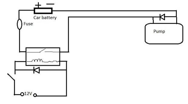
I am gonna make an easy circuit with a relay to control a pump.(see attachment)

I understand the principal, but I wonder if there is anything more I gotto think of, like resistors or something?


It is not to be used in a car.


I am thinking of using an car relay: 12V, Max 30 amp.

The pump use 12V and 4 amp.

The fuse need to be 4 amp?


Can the switch for example be wired directly to pluss and minus on the car battery or do I need a  resistor there?

Thanks!

Attachments:
image
  • Sign in to reply
  • Cancel
  • dougw
    0 dougw over 11 years ago

    The circuit is good the way it is.

    The fuse could be a little higher current - 5 to 10 amps, as long as the wiring and connectors can survive whatever current the fuse allows.

    The switch/relay power could be connected at the output of the fuse to protect the relay and switch as well.

    You could use (large) snubber diodes across the relay coil and pump to minimize arcing on the switch and relay contacts.

    • Cancel
    • Vote Up 0 Vote Down
    • Sign in to reply
    • Verify Answer
    • Reject Answer
    • Cancel
  • Former Member
    0 Former Member over 11 years ago in reply to dougw

    Thanks for your respond! image


    The switch will not be directly connected to the battery, but from another more convenient location (which allready have a fuse box).

    Could you explain this sentence:
    "You could use (large) snubber diodes across the relay coil and pump to minimize arcing on the switch and relay contacts."

    1. What is "snubber diodes"?

    2. What is "arcing"?

    • Cancel
    • Vote Up 0 Vote Down
    • Sign in to reply
    • Verify Answer
    • Cancel
  • D_Hersey
    0 D_Hersey over 11 years ago

    These are backward diodes that are typically in shunt across the load.  They should have a current rating similar to the current you are using.  Best to use about 25V Shottkys (or greater) here.  Your relay coil is another inductive load.

    • Cancel
    • Vote Up 0 Vote Down
    • Sign in to reply
    • Verify Answer
    • Cancel
  • D_Hersey
    0 D_Hersey over 11 years ago

    Some loads have a significant inductive component.  Motors in particular, other stuff.  A passive, linear load can be modeled upon a complex number.  The first term is resistance.  The second is reactance, which if it is positive in signum represents an inductance, negative signum indicates capacitance.  Your load is a relatively small resistance (high conductance) + fairly great inductance.


    Inductances source and sink potentials to oppose changes in the current through them, by establishing or diminishing magnetic fields in their surround.  When you first turn on your pump, a magnetic field is established by taking energy from your battery.  When you try to turn it off, the field collapses, inducing energy back into your wire.  The saw is that it (our inductor of interest) sources potential in an attempt to maintain the current going through whatever tried to break the circuit.  Initially, the potential will rise to whatever it takes to maintain the current, which is a function of the new (high) resistance of your switch.  The snubber diode is to protect the switch.  The 'area under the curve' of  the spike is going to be a the product of load inductance and load current /2.


    If this doesn't make sense, blame me, just woke up.

    • Cancel
    • Vote Up 0 Vote Down
    • Sign in to reply
    • Verify Answer
    • Cancel
  • Former Member
    0 Former Member over 11 years ago

    I didn't really understand that either(English is not my native language).

    Could you make a new drawing with those diodes included where they should be?

    • Cancel
    • Vote Up 0 Vote Down
    • Sign in to reply
    • Verify Answer
    • Cancel
  • D_Hersey
    0 D_Hersey over 11 years ago

    Alas, I am at home in the city and my shop is in the 'burbs, drawing program is out there.  Shunt means 'in parallel' or across.  Backward means that the diode is supposed to be in blocking mode during the normal operation of your circuit.  The diode across the load only 'comes on' after your relay turns off.  The little implicit arrow of the diode should be opposed to the current flow when your load is energized.


    Actually, 'snubbing' more properly refers to reactors used for this function, although the term 'snubber diode' is in common parlance.  It is probably just as well to call this diode a clamp.  What throws so many beginners is that their first encounter with this problem is in the context of unipolar stepper motors, where the diode in one transistor, due to the way the motor is wound, snubbs (see, I do it too) the load of its neighbor.  This throws them on the voltage signum.  Just remember that a coil or inductor opposes changes in current through it by sourcing/sinking potentials which appear on the switch attempting to do the changing.


    As for your fuse, go with around six Ampere.  You need some operational headroom.  The fuse protects against gross flaw.


    Ever seen a 'Jacob's ladder?'  That's arcing.  The potential from the spike is so high it breaks down the air and causes a spark.  A circuit that intentionally relies on the magnetic decay of an energized coil is called a 'flyback.'


    I think you should be fine hooking up directly to the battery.  I use sealed AGM (adsorbed glass mat) batteries for this purpose.

    • Cancel
    • Vote Up 0 Vote Down
    • Sign in to reply
    • Verify Answer
    • Cancel
  • dougw
    0 dougw over 11 years ago in reply to Former Member

    When the contacts in the switch or relay open, the inductance in the pump and relay coil will cause high voltage spikes which cause sparks between the contacts. With enough on/off cycles these sparks will eventually erode or burn the contacts.

    Snubber diodes short out the energy stored in the inductance when power is removed and eliminate the voltage spike. This is very important in circuits where a high voltage spike would damage the circuitry - in your circuit it is not essential but will reduce electrical noise and make the switching devices last longer.

    image

    • Cancel
    • Vote Up 0 Vote Down
    • Sign in to reply
    • Verify Answer
    • Cancel
  • D_Hersey
    0 D_Hersey over 11 years ago

    Actually, if your relay capacity is marginal, welded contacts, which implies device destruction, is on the table.  In some instances, such as very large solenoid-operated valves, or stepper motors with mechanically reactive loads, we actually have to explore the dynamics of the anti-spike apparat.


    In your case, as in most, an anti-parallel diode across the load, rated for the operating current, is all you need or need to think about.

    • Cancel
    • Vote Up 0 Vote Down
    • Sign in to reply
    • Verify Answer
    • Cancel
  • Former Member
    0 Former Member over 11 years ago in reply to dougw

    Thanks again!

    Which kind of diode should I use? could you recommend some?

    I do understand enough to use it now, but I do wonder:

    When you turn off the pump, it will "produce" som ind. current, which will go to the relay or back into the pump?

    • Cancel
    • Vote Up 0 Vote Down
    • Sign in to reply
    • Verify Answer
    • Cancel
  • D_Hersey
    0 D_Hersey over 11 years ago in reply to Former Member

    You paid for the electricity when you turned the pump on.  Have you ever plugged in a fan and seen a spark?  More likely when you unplugged it.  When you plug in an old stereo, the spark comes initially, 'cause it's a capacitive load.  There are two forms that analogize to mechanical inertia in electronics, magnetic and charge.


    Vishay VS-6TQ035 might be a good choice for your pump.

    1n914 would work to clamp the coil if it uses less than an ampere.

    • Cancel
    • Vote Up 0 Vote Down
    • Sign in to reply
    • Verify Answer
    • Cancel
>
element14 Community

element14 is the first online community specifically for engineers. Connect with your peers and get expert answers to your questions.

  • Members
  • Learn
  • Technologies
  • Challenges & Projects
  • Products
  • Store
  • About Us
  • Feedback & Support
  • FAQs
  • Terms of Use
  • Privacy Policy
  • Legal and Copyright Notices
  • Sitemap
  • Cookies

An Avnet Company © 2025 Premier Farnell Limited. All Rights Reserved.

Premier Farnell Ltd, registered in England and Wales (no 00876412), registered office: Farnell House, Forge Lane, Leeds LS12 2NE.

ICP 备案号 10220084.

Follow element14

  • X
  • Facebook
  • linkedin
  • YouTube