In this little series, I'll automate this exercise: Measure the Analogue Front-end of Data Acquisition Board for Pi Pico .
In the second post: make the function generator generate DC test signals
|
summary:
|
LabVIEW flow to control function generator DC output
I've developed a driver for the function generator earlier: MULTICOMP PRO MP750065 Function Generator - Programming Pt6: LabVIEW Driver Lib: High Level Functional blocks .
In this flow, I'll use those blocks to set the instrument to DC mode, switch on the output, and let it hop between -4 and +4V. The hop will be controlled by an incrementor block that I made as a LabVIEW exercise: LabVIEW: Module to Generate Step Increments .

Set up the function generator
The generator is set to DC, offset 0V, and output switched on.

I've moved this to its own VI. That leaves more real estate for the main flow.
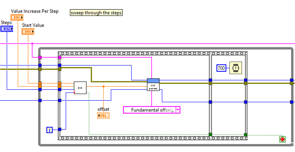
Sweep through offsets
The generator starts at a value, then increments that value for a number of times. This is parameterised.

If you set the start value to -4; increment to 0.5 and steps to 16, it 'll bop from -4 to +4V in 0.5V increments.
If you start at 4, set increment to -0.5V and steps to 16, it 'll hop between +4 and -4 in 0.5V decrements.
The waiting time is long enough to deal with settle time, and the time needed when crossing 0V. The generator switches polarity with a relay and needs time to do that. Later, the measurement block will fit after that wait section.
Wrap up after testing
The offset is set to 0V, and output switched off.

This is also placed in a submodule to save space on the main flow canvas.

