Introduction
This is the final posting in the series to wrap up the challenge although I will continue to add features. I will summarise the work so far, demonstrate the framework and explain how it all hangs together. One of the challenge requirements is for the final blog to be standalone so unfortunately this is a long posting because there's so much material to cover to properly explain it all.
Note there is a lot of new material in this post, not covered by the other six.
I've structured the posting in a way that I think makes most sense. I scratched my head a bit on where best to place the description of the project and the demonstration of the project. You may just want to get into it, and then read how it works; but equally you may want to approach the demonstrations having some idea of what is going on under the covers. The demos do describe this of course but either way, review the Project Description and Demonstrating the Framework section in the order you think it will help you better understand it.
EDIT: 27th October. I've added YouTube links to the videos as it appears they aren't being served very well and they need to be viewed in HD. These are exactly the same videos, and will open in a new window.
Table of Contents
Links to Supporting Blogs
The links are to posts where I cover in more detail some of the material in this blog and do form part of my submission to the Challenge. However, the final submission is meant to be standalone so the parts that are specifically relevant to this submission I do cover again - it's not necessary to read these additional posts. In addition, the Framework has evolved since this were created so some aspects are different. For example, I no longer treat the Framework as being for "Test Applications" as it is generic enough to be used for any purpose that involves interacting with Instruments, so I now refer to "Interacting Applications" and changed some code accordingly. Test Automation is one use case in what can be achieved with the framework.
Learning LabVIEW: 1 - Developing a Hardware Abstraction Framework - Introduction and Getting Started
Learning LabVIEW: 2 - Designing the Hardware Abstraction Framework
Learning LabVIEW: 3 - Project Organisation with Libraries and Folders
Learning LabVIEW: 4 - Anatomy of a Class
Learning LabVIEW: 5 - Setting up the Raspberry Pi PICO and Accessing Instruments
Learning LabVIEW: 6 - Anatomy of a VI
Project Description
The Hardware Abstraction Framework (HAF) is an extensible LabVIEW library designed to abstract the complexity of interacting with multiple test instruments and coordinating interactions across them. This interaction could take the form of a set of Tests, e.g. of a new product under development, or connection to devices, instruments, machines to obtain operational data. Anything that uses a protocol understood by LabVIEW and that can be automated with commands. SCPI is one well known example and an interaction easily accessible to engineers with typical bench top instruments as it is a widely used standard.
This section of the Blog is intended to describe how the Framework works and how it is use and this makes for a quite detailed description of the project. As part of doing that, it pretty much covers the design as well - although some further design detail is given in a following section.
It's worth mentioning at this stage that the Framework was developed using LabVIEW Classes and an Object Oriented methodology. What follows often refers to named classes in the Framework.
Downloading the Hardware Abstraction Framework
To follow along, it might be beneficial to download the project assuming that you have LabVIEW 2023 installed. The Framework is available to download as a Project Template from my GitHub repository: https://github.com/ad-johnson/LabVIEW_Project_Templates/tree/main (new window)
It should be cloned to the LabVIEW Data\ProjectTemplates directory as pointed at by the Default Data Directory (you may have to create \ProjectTemplates as a subdirectory - note, no space between Project and Template!):
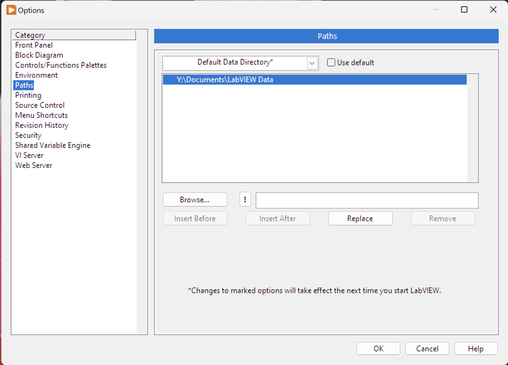
Select Options from the LabVIEW menu. Restart LabVIEW if you make any changes to the directory used. Once it is cloned, you should be able to create a new Project and select the Hardware Abstraction Framework template; LabVIEW will copy the framework into your actual project directory.
Overview
The basic approach to instrument interaction is to send one or more commands to one or more instruments and process the results. Some interactions will be simple, one-off commands; others will be more complex involving multiple commands over multiple instruments, over an extended period of time.
This framework attempts to meet these needs and has some basic concepts which a user of it should be aware of:
- Interacting Application: this is not a framework class or construct; instead it is a term used for the application that uses the Framework to interact with instruments. It is the application you will write.
- Command: a Command is an instruction sent to an instrument that it can understand, run and, if necessary, provide a result. The framework separates out instrument specific commands from instrument independent commands which means that you can build interactions up without a detailed understanding of instrument-specific syntax. For example, you could use a command such as Identity rather than *IDN?. The framework calls these commands and there are two types: a WriteCommand - sends a command only - and ReadCommand - sends a command and then reads a result.
- Instrument: a representation of an actual physical device to be used. This can be anything that can be driven by LabVIEW and the framework doesn't require instrument-specific drivers. Instruments are abstracted so that you can use them 'generically' leaving the framework to do any necessary translation into 'specifics'. Obviously, to use your own instruments you will need to provide some of this translation but the benefit will be that your overarching interactions can be generic and reusable across different instruments, e.g. substitution of one manufacturer's DMM with another manufacturer's DMM without change, or only minimal change, to the interacting application. The framework calls these instrument abstractions Drivers (in line with LabVIEW terminology) and the specific instance of a Driver, Instrument. Drivers provide the interface between the framework and an instrument.
- Interaction Processor and Directors: these actually control the running of Commands against a Driver in a controlled manner. Essentially, they control the overall execution flow and can utilise pre-defined events and messages to callback to the Interacting Application itself. Complex processing can be controlled by using specific types of Directors: CommandDirector (single-shot); RepeatingDirector (numbered iterations); ContinuousDirector (infinite iterations until stopped); and TimedDirector (timed duration). The InteractionProcessor is the master controller and interacting launch point.
The basic approach to running an interaction is to follow these steps:
- Instantiate a Command that represents the command you wish to use.
- Associate an Instrument - a concrete instance of a Driver to that Command which will represent the instrument to send the command to.
- Repeat this for each Command you want to run in your interaction.
- Associate these Commands to one or more CommandDirector instances, selected on the basis of how you wish the commands to run. For example, you may select a CommandDirector to run once an Identity Command and a RepeatingDirector to run a Measure Command 10 times.
- Associate these CommandDirectors to an InteractionProcessor and run the interaction. The Processor will process each CommandDirector until they have finished, results are sent back to the Interacting Application as either a Results Message or a Results Notification (your choice) and the Processor will listen for events such as Pause, Resume, Stop and modify the processing accordingly.
- Your application can listen out for a Done event to know when processing has finished; it can also look for Result messages or Result Notifier notifications to handle and display produced results. How complex you make these is up to you but check out the examples for ideas.
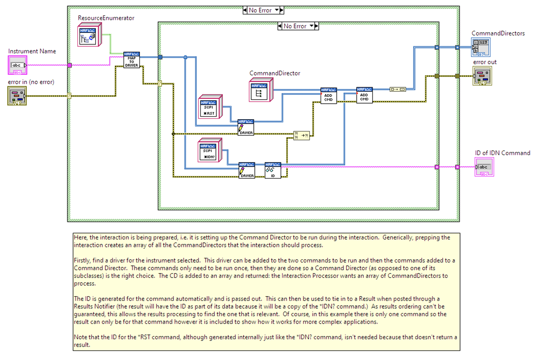
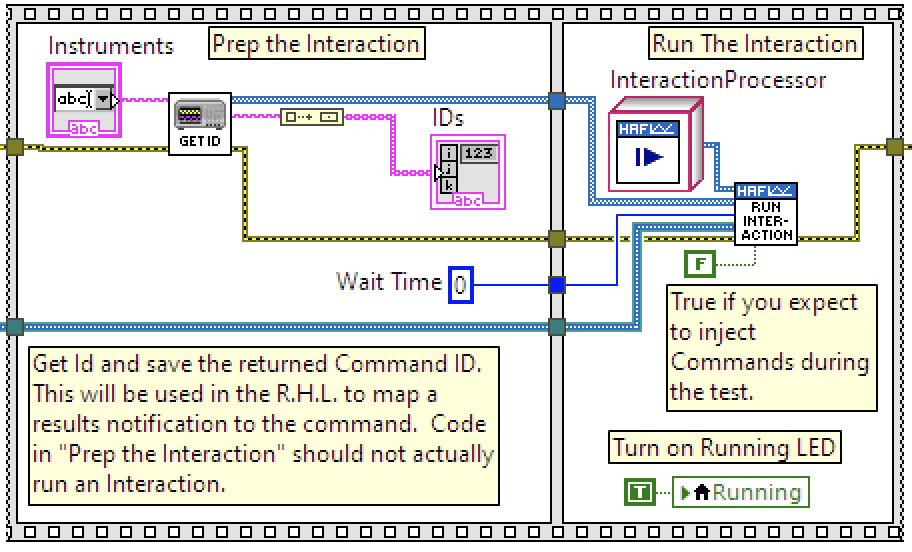
Here's how one of the examples, Instrument Identification, does this. First image, is steps 1 to 4 and second image is step 5. Note that these are just snapshots of the framework and not a complete picture.
| {gallery}Basic Approach to Running an Interaction |
|---|
|
Image 1: Instantiating two existing Commands, adding the Driver (instrument) and then adding the Command to a Command Director. Notice that the Command Director can manage more than one Command. |
|
Image 2: "Get ID" is image 1 and its output is a CommandDirector which is added into an array and passed to an InteractionProcessor to run. The greenish wire under "Wait Time" is carrying a Results Notifier. This is step 5. Don't worry about the other constructs you see: this is a snapshot of a larger application which will get covered in more detail in the Examples section later in the post. |
Many Commands in the Framework can be used as-is in applications but there may be Commands that are missing for your purpose. You can create your own by following the pattern established for the existing ones.
Similarly the CommandDirectors are likely to be sufficient for most applications but again, you can create your own by following the pattern established for the existing ones.
Unless you use the same instruments that are provided by the Framework (as implementation examples), it is most likely that you will have to create your own for your instruments. Once again, you can follow the pattern established for the existing ones; you may want to consider uploading these to the repository for inclusion in a future release.
The rest of this section describes the Framework in more detail: how it has been designed and how it is used.
Interacting with the Framework
Your application will engage with the Framework through other means that just asking it to process Commands. The Framework is set up to respond to Events your application can raise:
- Pause: Processing will be paused at the end of the current processing of CommandDirectors - remember these could be long-running. It does need to finish any currently running processing cycle (covered shortly) so as to ensure instruments are not left in an unknown state. The Pause will timeout after 60-seconds and all processing will finish with an error being returned indicating the timeout occurred.
- Resume: Processing will be resumed if paused.
- Stop: Processing will stop immediately after the current processing cycle of CommandDirectors - again, so that instruments are not left in an unknown state.
- Inject: CommandDirectors (with Commands) can be injected into a running interaction for execution. They will be added to the end of the current set of CommandDirectors that the InteractionProcessor is processing. The InteractionProcessor needs to be primed to Handle Injections when it is launched otherwise it may finish before CommandDirectors can be injected.
The Framework will interact with your application through events as well:
- Done: Raised by the Framework when all processing has completed. you could, perhaps, on hearing this event, unblock the UI, display any messages, quit the application, write results to a database and so on.
It also engages with your application via messages on a Notification Queue or via a Notifier:
- Result: When a ReadCommand runs and receives a result, it stores that and posts itself on to the Notification Queue as message data for the Result message. Your application should be waiting to receive these messages so you can do something with the result. The Command knows how to process a raw result (from the instrument) into something useable and of a specific data type; any results for parameters can also be processed into useable information. Each Command has a unique ID and you can tie a result on the Notification Queue to a specific Command instance so your application knows how to handle the result.
- Result Notifier: Create a Notifier and pass it into the Framework. Each result received will be posted through this notifier to the Interacting Application. As for Result, the data passed is the ReadCommand itself which is holding onto the result.
Which to use? The Framework may block the Interacting Application when it is called, until all processing is finished. Whilst the results will be posted as messages on the Notification Queue, your application won't get a chance to process them until the Framework is Done. This is fine for simple applications but no use for long-running ones. In the latter case you will want a parallel thread waiting on a Notifier to appear containing the result. These can be processed as they are generated by the Framework, irrespective of whether the rest of the application is blocked.
Events, Messages and Notification Queues are all established by the Framework and are available for your application to use. You must create your own Notifier to pass into the Framework if you take this approach for result processing, shown in the image below (so simple enough.)

Examine the example applications to see how to use Events and Notifications. These example applications form part of the Project Template and can be used as a base for building your own applications.
Framework Structure
The Framework has been mostly written using LabVIEW's object oriented features so the majority of engagement between your application and the Framework will involve the use of classes; extensions to the Framework will likewise be done through extending existing classes and overriding methods.
As the source is provided unlocked, you are encouraged to use one of the examples and single-step through it observing how the framework is called and how interactions play back and forth.
In terms of processing, the Framework follows a Queued Message Handler pattern which is described within one of LabVIEW's examples. The examples, although simple in themselves, also use this approach to provide a basic pattern for your to follow in your own applications.
Core Classes
Note that the following images are intended to show main classes and methods and are not a complete picture of the Framework.
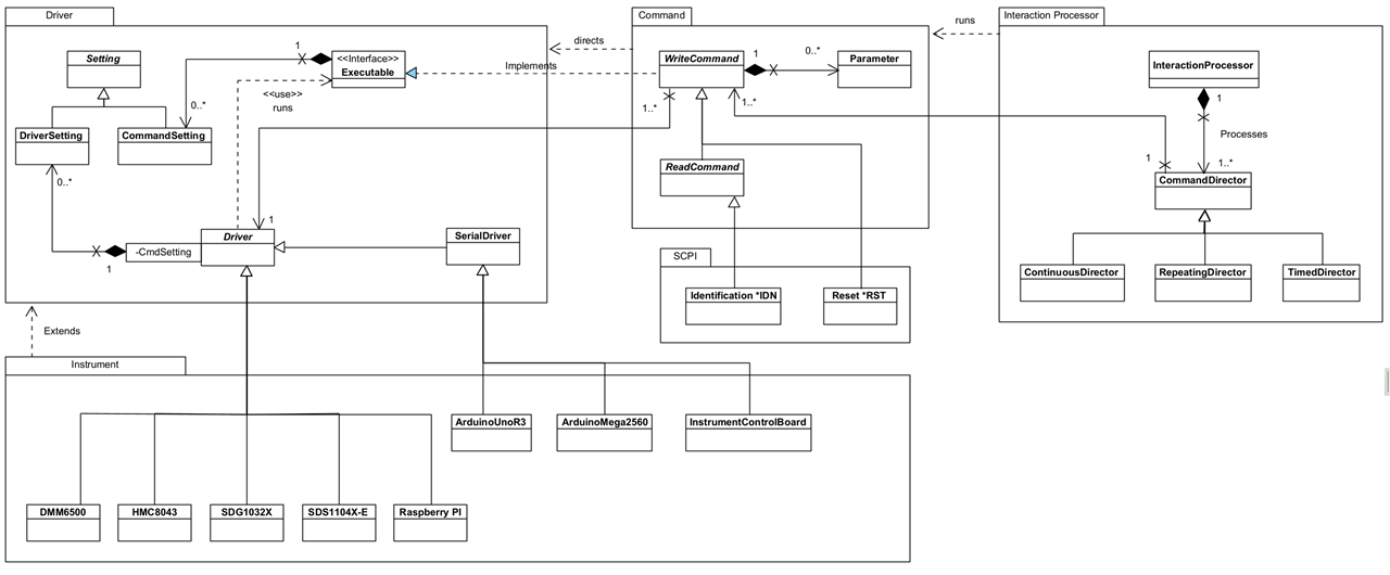
The Class Diagram above shows the classes and relationships that form the core element of the Framework. It's broken down in the following sections.
Command
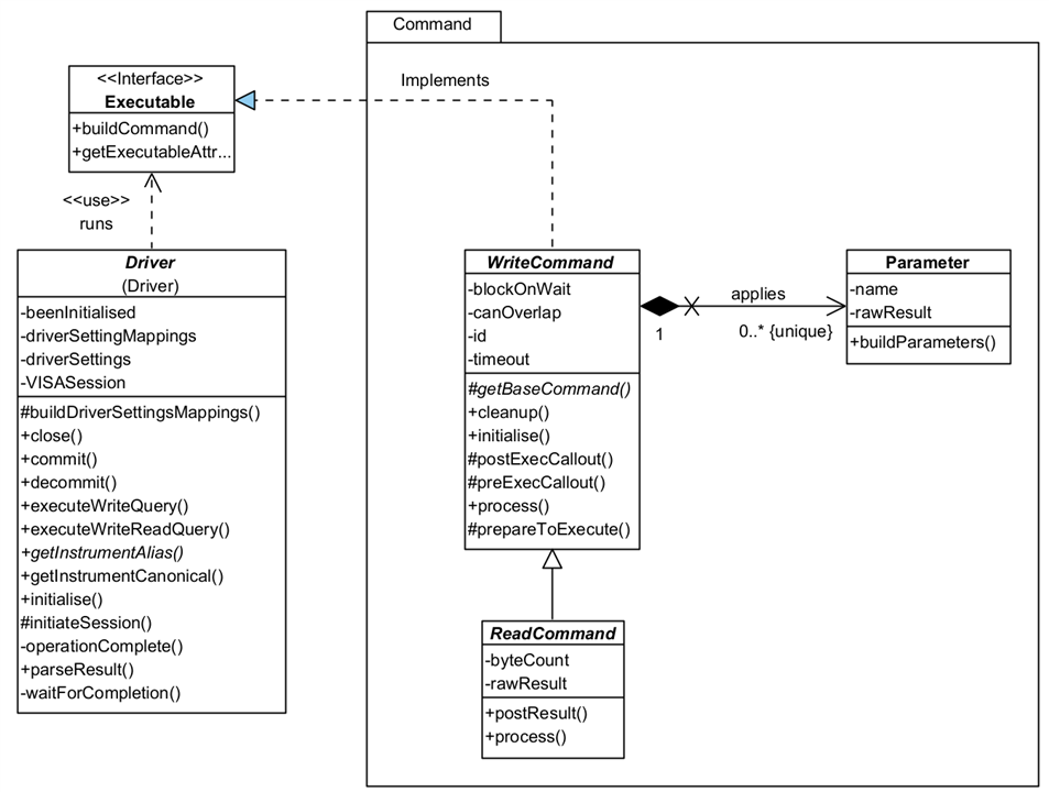
A Command represents an instruction that can be sent to a Driver for running on an Instrument. As the Framework evolves over time, these will become much more than just commands for Drivers, and will represent other execution constructions such as optional pathways, or directives to help with processing.
There are two types of Command:
- WriteCommand: represents a command that can be sent to an instrument but which requires no response.
- ReadCommand: represents a command that can be sent to an instrument and for which a response or result will be returned. You will note it inherits some of its functionality from WriteCommand: you don't need to run a WriteCommand and a ReadCommand as the latter incorporates the functionality for you.
A Command is associated with a Driver whose responsibility it is to undertake any instrument specific translation of a command. The Framework will arrange for the Driver to run the Command at the appropriate moment. Note that a Driver knows a Command by its interface, Executable.
There are two ways a Driver can run a Command:
- immediately: as it says, the Driver sends the command straight to the instrument.
- when able: in this case, the Driver will wait for the instrument to finish processing any existing commands before sending this one.
A Command controls this with its canOverlap property: if true, the Command will run immediately; if false, when able.
A ReadCommand will hold a result returned from the instrument. It does so in a raw form, rawResult, and provides no interpretation of that result until asked to do so by the application calling buildResult. The application will be notified of an available result via a Result messaged raised on the Notification Queue or a raised Notifier. The result data is the same in both cases: the Command itself is passed back to the app and can be used to obtain the result as a raw value (String) or a typed value.
Some Commands can take parameters to send along with the base command. These are represented by the Parameter class. The Framework will automatically add any requested parameters to the command before it is sent to the instrument: you just need to add the ones you want to the Command when you create an instance of it. A Parameter will hold a result if available, and is capable of parsing that into a typed value for the application.
CommandSettings (available via the Executable interface implemented by WriteCommand as shown on the main Class Diagram) are a way of provisioning configuration settings for Drivers, independently of how they may be applied to an instrument. For example, you might use a CommandSetting called 'Settling Time'; on one DMM it might equate to 'Settle Time' whilst on another it might be 'Settling Duration'. You won't care - the Driver will map these to instrument specific configurations, once that mapping has been set up (one time only.)
You'll see from the Class Diagram that CommandSettings provides no specific behaviour so is really just a placeholder for now. There is more information in the Settings section below, but the functionality for settings hasn't needed any specific behaviour for Commands in the current version.
So what do you need to do to use the Framework? Basically, just use one of the existing Commands and add it to a CommandDirector. If none of the existing Commands are of any use, then create your own by following the pattern established by an existing one.
Here's an overview of four Commands:
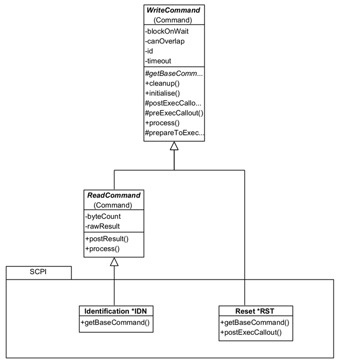
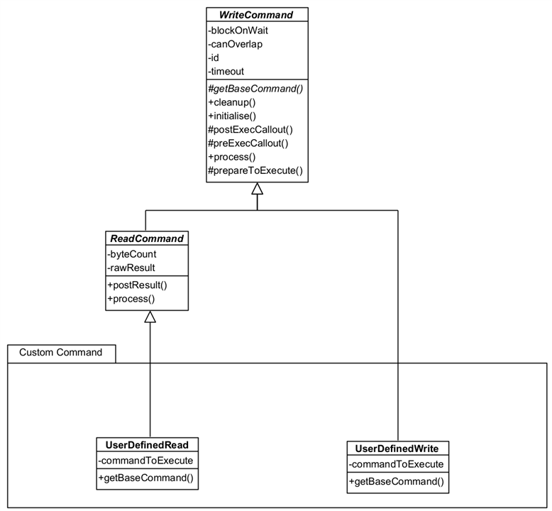
You can see that all that is needed is a concrete implementation of getBaseCommand() (the command as it appears without any parameters or end of line characters.) The Reset Command has also provided a postExecCallout() override which is called after the command processing is completed (write or write and reply) so that additional processing can be done. This is a callout and only needs an implementation when needed. ReadCommand classes can also add additional methods such as resultAsDouble() or resultAsTimestamp() etc. which parse a raw result into a useable format for the application. That isn't strictly necessary as the Framework provides helper VIs for that.
The UserDefinedRead and UserDefinedWrite are generic Commands that can be loaded with any command string you wish and can be used instead of creating specific Command classes.
These Commands aren't strictly part of the Framework because they would normally form part of an Interacting Application. They are provided with the Framework because they are (a) re-usable and likely to be so in any application; and (b) form a good example to build upon.
Driver
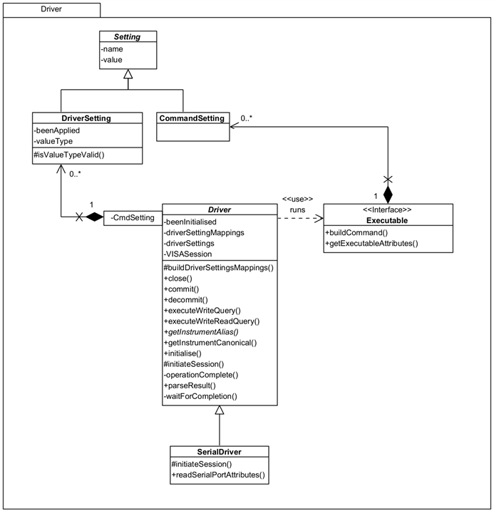
Driver is responsible for interfacing with actual instruments providing the necessary mappings between a generic language and instrument-specific language. By doing this, a user of the Framework can standardise on names for things like commands, parameter names, setting names and so on and leave the Driver to translate on an instrument by instrument basis.
SerialDriver should be used for instruments that will use a Serial communication method, e.g. Arduino Uno. This operates the same way as the standard driver but expects a device to be available on a mapped COM port rather than on, say, a USB port.
It is envisaged that future versions of the Framework will be able to load mappings between the generic and specific from an external source to allow applications to be more configurable.
A Driver will execute a query for an Executable when directed by the Framework, obtaining a response as necessary. Executable is an interface to be implemented by a class that can provide a command to run on an instrument - implemented by WriteCommand in the Framework. It provides a 'separation of concerns' between Commands and Drivers and prevents a cyclic dependency between the two parts of the Framework.
DriverSetting are configurable settings for an instrument and are mapped between a generic CommandSetting and the instrument setting. More information is available when I describe Settings below.
So what do you need to do? When you instantiate a Command you need to give it a Driver, as implemented by an Instrument as a concrete subclass to be used to process it. These can be selected by name, say on a UI or as some created constant, and the Framework will use that to identify a specific Driver for you - it only requires that the Driver implements getInstrumentAlias() to return the known alias name that the instrument identifies with in NI-Max. If you prefer to work with canonical names then you need to implement getCanonicalName() as well. It's likely you will need to create your own Driver instances, unless you use the same instruments as me, but you can use the existing ones as examples to draw from:
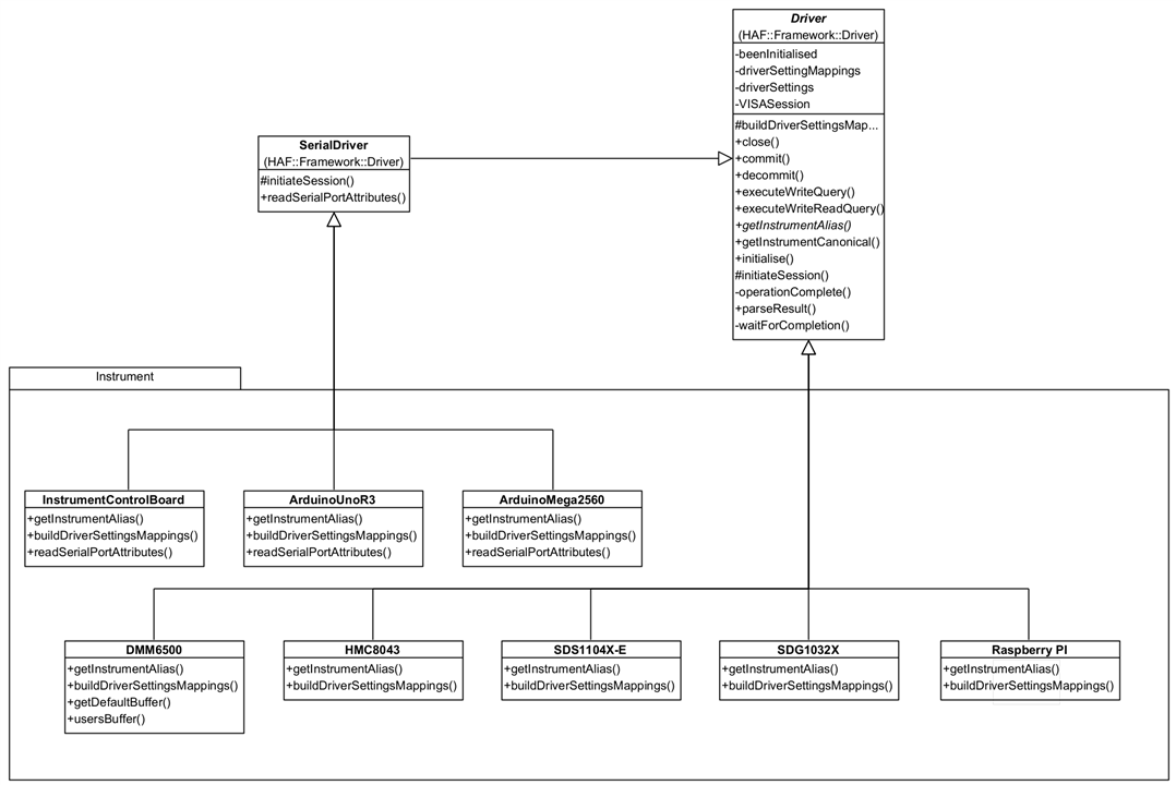
You can see here that all you need to provide is a concrete implementation for buildDriverSettingsMappings() and getInstrumentAlias(), and override readSerialPortAttributes() if the device needs to use values different to the Framework defaults. The Framework handles everything else.
The Arduino Drivers (and Instrument Control Board which uses an Arduino) provides an overridden readSerialPortAttributes() because I want to communicate with it at 115200 baud, rather than the default 9600 baud, and it needs the initialisation to wait 2000ms after opening a port to ensure the Arduino will be available to process commands.
These concrete implementations are available in virtual folder Implementation. Strictly, this isn't part of the Framework as it is not abstract, but part of the implementation of an Interacting Application. However it is provided along with the Framework because they are (a) re-usable; and (b) a good example to build on.
Setting
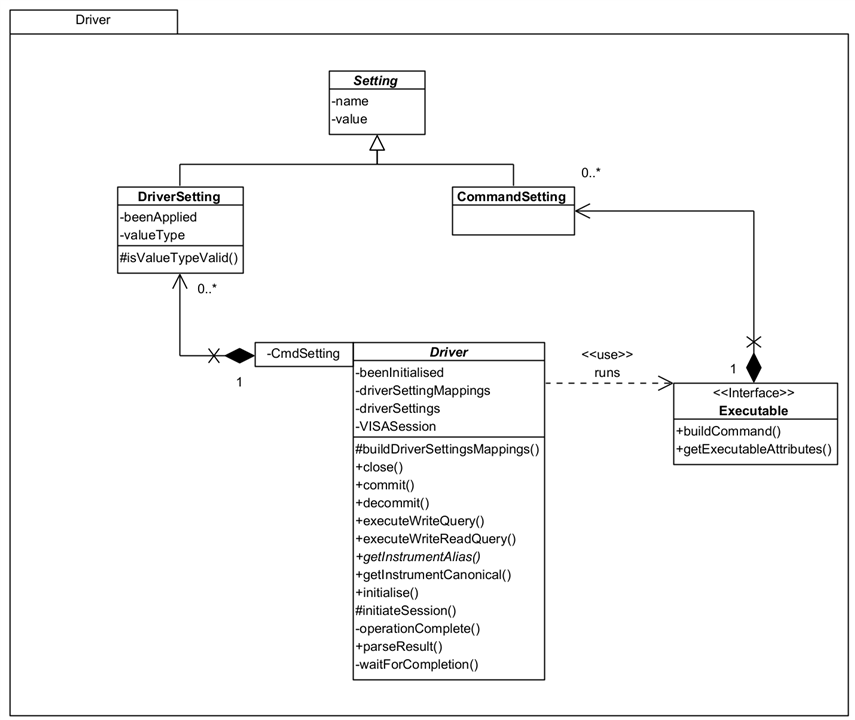
Setting is meant to represent a specific configuration setting that can be sent to the instrument by the Driver. You can see it has a name and value.
There are two types of Setting:
- DriverSetting: This represents setting as know to the instrument. The type is so that the Framework can properly parse the value; beenApplied is set by the Framework once the setting has been made so that it doesn't constantly send it on every command (see the section on the Process flow) - this could be reset so it is re-applied. In fact, if you use a Reset Command, it ensures that the settings will be re-applied.
- CommandSetting: This represents a generic, non-instrument specific setting, i.e. a setting you can refer to for all instruments. The Driver maps this setting to a DriverSetting which then removes any concern of naming differences. E.g. you could refer to a setting 'Settle Time' and on one DMM is might actually be 'Settling Time' and on another DMM 'Time To Settle'.
You add CommandSetting to the Command as you instantiate it. If you create a Driver, you must also create a set of mappings from CommandSetting to DriverSetting; if a setting is not used by a particular Driver, use Ignore as the mapped name and that's what the Framework will do.
Processing
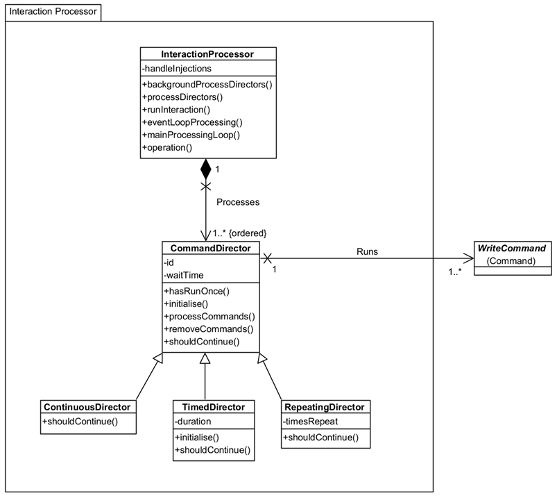
- CommandDirector: The Director controls the processing of one or more Commands. Each Command is processed at least once and depending upon the choice of CommandDirector, multiple times.
- CommandDirector: processes each Command once only.
- RepeatingDirector: processes each Command timesRepeat times.
- ContinuousDirector: processes each Command continuously until ordered to stop. Your application can do this by raising a Stop event. You could abort the running VI but this may leave the instrument in an unknown state (recover with a Reset Command in the next application run.)
- TimedDirector: processes each Command for a minimum duration of time.
- InteractionProcessor: This is the framework's main control processor, responsible for processing all CommandDirectors. You only need one instance of this and processing starts by calling member runInteraction(). The InteractionProcessor listens for Stop, Pause, and Resume events, acting accordingly on the CommandDirectors. Although not a member property, runInteraction() takes a waitTime as a parameter which acts the same way as waitTime on the CommandDirector, except the wait is between Directors not Commands.
Processing Loop

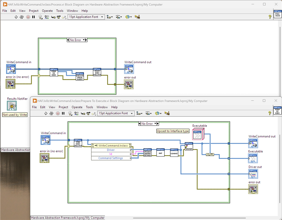
- Pre-Exec Callout: run any Command specific code before the Driver runs the command.
- Update Driver Settings: add any new CommandSettings to the Driver, which will map them to Driver Settings
- Initialise: tell the Driver to create a session to the Instrument if one doesn't already exist
- Commit: send any unprocessed Driver Settings to the Instrument
- Execute Write Query: send the command to the Instrument
- Post Exec Callout: run any Command specific code after the driver runs the command.

- Execute Write Read Query: sends the command to the Instrument and reads a result. Results are issued for the Command and the Parameters as applicable. See the Documentation tab on the member for details on how the result is parsed into constituent elements.
- Write Raw Result: saves the unformatted Instrument response for later processing
- Write Param Values: saves the unformatted Parameter responses for later processing
- Post Result: if a Results Notifier was passed with the Command, the Command adds itself to the Results Notifier and raises the Notification; otherwise, it adds a Result message on the Notification Queue with the Command set as message data. In either case, the Interaction Application should read this message and arrange for the result to be processed as required - not forgetting that results may be stored in the parameters if used. Note that that a result sent as a Notification can be processed immediately, whereas the result on the Notification Queue will be held there until the InteractionProcessor has finished all CommandDirectors and is "Done".
Examples
1 - Instrument Identification
2 - Command Injection
3 - Waveform Measurement
Finally...
Demonstrating the Framework
Detailed Walkthrough with a Simple Example - Obtaining an Instrument's Identity
I'm going to use this simple example to go through the Framework in some detail but I will break it down into shorter videos, or at least as short as I can make them. Apologies to those readers who don't like videos but I feel it would be nigh on impossible to explain this with just static images. In reality, for such a simple requirement, using the Framework is overkill but it is a good vehicle to see what is happening. Video 8 is a running walkthrough with breakpoints set and the use of probes to show values if you'd prefer to skip to that.
The demonstration uses the Pi PICO with Jan Camp's PST firmware installed.
1 - Overview of the Interaction Application, Instrument Identity, and a brief look at the block diagram.
In this video, I give a description of what the example application does and how it is intended to be used as a base for future, more complex applications. There's also a really quick walk through of its block diagram to just set the scene for future videos.
2 - The Event Processing Loop
The Interaction Application follows a LabVIEW pattern called Queued Message Handler (discussed later in this post). Basically, it consists of two parallel running loops: one is handling events, e.g. from the UI, and the other is processing messages which is driving it as a state machine. As the loops are running in parallel they are both independent but can pass interactions between themselves, notably, the Event Loop drives the Message Loop as a result of events that occur.
This video describes the Event Processing Loop used by the Instrument Identification application.
3 - The Main Processing Loop
This is the part of the Framework that actually controls the running of the interaction and execution of commands. It continuously loops waiting on a message on the Notifications Queue and processing it. These messages from the State Machine of the application, described in the section on Design further below in this blog. In this example, the actual running of commands to Get ID occurs in the "Action1" state which is linked to the Get ID button on the Front Panel.
4 - The Results Handling Loop
Results are handled two ways by the Framework. The simplest, is that it collects the results as it executes the commands and then presents them all in one go by transitioning into the "Results" state in the Main Processing Loop. The alternative, is to notify the Interacting Application as a result is generated so that the result can be processed straightaway. One way of thinking about it is if the Interacting Application is long running - e.g. stepping a voltage and measuring the effect - it doesn't have to wait until it has finished stepping through 1000mV to show you the result, but can show what happens at every voltage step.
The Instrument Identification example doesn't really warrant the use of Notifications as it is best suited to using the "Results" state but it's used because it demonstrates the more complicated (but not complex!) way of doing it.
5 - Running Commands Through the Framework - Interaction Application Preparation
I'm now coming on to a detailed walkthrough of using the Framework. In this video, I talk about preparing the Command Directors and Commands that will be run by the framework (Command Directors and Commands are part of the Framework as well of course.) This preparation is something that all Interacting Applications will have to do although will be specific to the application itself.
In this video you will see the one part of the Framework which I haven't yet automated: mapping a selected instrument name to an actual concrete Driver (Instrument subclass.) Currently, it is a hard-coded part of a User's Interaction Application but one of the improvements I want to make is to find out how I can use configuration generated by NI-MAX to do this automatically.
6 - Running Commands Through the Framework - What Happens When they Run
Here, I step into the Framework and cover off how it runs and the states that it passes through in processing the Command Directors and the Commands. To keep the videos at a reasonable length, I don't delve into the Process mechanics in this video but do cover off the other states. The next video will go through actually running Commands against the Instrument.
7 - Running Commands Through the Framework - How are Commands Processed
Here, I go through how commands are actually sent and how results are read, stored and passed back to the Interacting Application.
8 - Instrument Identification Example Step-Through
In this video, I place some breakpoints and run through the example stepping into VIs so it's possible to see visually what it happening. I use Probes to show data values on the wires. It's possible to see the parallel nature of execution as different parts of the application run in ways that aren't wholly expected.
Example of Command Injection Whilst a Test is Running
This example shows how it is possible to send additional commands to the Interaction Processor whilst it is running. This allows, for example, the changing of values on a Front End Panel to affect the running interaction. I show the example running, then show how the commands were constructed and how injection actually works. I do not go into the same level of detail as I did for the Instrument Identification example.
The demonstration uses the Pi PICO with Jan Camp's PST firmware installed.
Example of a More Complex Test - Obtaining and Charting Changing Readings
This example shows a long running interaction that is obtaining resistance results from a DMM connected to a Trimmer. It uses the SCPI command :MEASure along with a function, a buffer and parameters, so: :MEAS:RES? "mybuffer" RESULT, TSTAMP (the Framework builds this command up.) In the video I show it running, and the impact of adjusting the Trimmer so different values are obtained. It also shows the use of the Pause and Resume buttons.
Design Approach
Until this challenge started I had no experience with LabVIEW although I did have some experience with LabVIEW NXG two or three years ago. The training videos were a good, albeit simplified, introduction and are worth watching to get some idea how to actually develop in LabVIEW. The rest of what I needed to know and understand came from the NI LabVIEW forums, the online LabVIEW manuals and various YouTube videos. I spent some time immersing myself in the technology so I could get a good feel for it; I have 30+ years of experience in IT, including many years as a developer, so I usually find that I can pick up a new development language/tool relatively easily - at least, I tend to know what to look for and what to look out for! I also have some experience with visual programming through the IBM VisualAge tools that were marketed and sold during the 1990s and early 2000s, although these are somewhat different as they still required dropping down into Smalltalk or Java code.
The idea for the Hardware Abstraction Framework originally came from needing to coordinate multiple instruments to test some of my personal projects. I have some experience of developing application frameworks for a variety of problem domains and this particular "problem" seemed like a good fit for abstracting out the main elements of instrument interactions so that I could reuse that across test applications, automate the testing and collating of results.
I'm experienced in object oriented design and development and that's the approach I took with this project: LabVIEW supports object oriented development and it feels like a natural fit for a framework that is expected to be extendable. The extendability was important to me, I don't want a solution that is locked into a specific set of bench top instruments or a particular test language. Later, or rather later on in the development, it struck me that whilst I'd thought about the framework in terms of Test Automation, it was flexible and extensible enough to be useful for anything that required interaction with instruments. Obviously testing during product development is going to be a core use case but thinking a bit more widely, it could just as easily interface to instruments to obtain running data. For example, in my volunteering with The Turing-Welchmann Bombe team, it would be simple enough to hook a laptop running an application sitting on this framework to pull running data from the machine via a DMM, an oscilloscope and a signal analyser.
I may well discuss this in terms of testing in order to keep it grounded in something familiar to a reader and to hook design thinking on, but it's not stuck in that use case. The design is discussed in detail in the previous section, so here I'm only describing how I went about designing the framework.
Requirements
Thinking about interfacing LabVIEW and instruments, what am I trying to achieve? Fundamentally, when I automate an interaction I will create a command in a syntax the instrument understands, send it and, if appropriate, read a response and process it. Typically, I would likely be sending multiple commands and if I'm going to the trouble of automating this, then it's just as likely that multiple instruments are involved and sequencing and coordination between them is required. These interactions, tests, whatever you want to call them could be one-offs, repetitive, or perhaps over a long duration (soak testing); perhaps a combination of all three. Instruments these days seem to provide a SCPI interface but generally only a subset of available commands that are relevant; they may have variations in the parameters they accept on common commands. There are also instruments that may not offer a SCPI interface but perhaps a home-grown syntax, e.g. an application running on an Arduino. The Bombe is an electrical circuit tester so talks no language, but there are certainly events that occur during a decoding run that could be considered trigger points for extracting signal data.
I came up with the following high-level requirements:
- Run commands against one or more instruments connected to the PC that are discoverable by LabVIEW.
- Be capable of running multiple commands in any one interaction.
- Encapsulate the device-specific communication protocol within the framework.
- Work with commands in a form that is human identifiable rather than programmatic and that is technology/syntax independent. E.g. work with a command "Identity" rather than "*IDN" or "Ident". Leave it to the framework to handle any translations from "English" to "technical" (perhaps a future iteration could localise this.)
- Be able to create interactions that are instrument independent, e.g. be able to swap one manufacturers DMM for another's without having to rewrite them.
- Be able to write interactions that can be run once; for a specified period of time; repeatable one or more times; or run until user intervention is made.
- I wanted commands to be grouped in these interaction modes so that I could, essentially, write simple programs to drive the instruments. It was important to keep it simple, at least for now, so whilst they could be run in different ways, I wasn't going to introduce branching or conditional paths.
- Provide an application that can be reused or modified as a starting point for future applications - fits in well with using LabVIEW Project Templates.
- Provide callout mechanisms at appropriate points of the framework to allow the execution cycle to be modified for specific scenarios.
It turns out that there's a fair bit of complexity encapsulated in those statements!
Iterative Design
As I've already covered the design in some detail whilst discussing how the Framework works in the Project Description section, I'm not going to go into detail here again. I took an iterative approach to the design - which is a fancy way of saying "I thought about something, tested it with a little program in LabVIEW, then came back and updated the design". I had no intention of creating a detailed design because it would never stay up to date.
I've been used to capturing designs in UML and did so for this project, using Visual Paradigm Community Edition as a tool of choice. I thought it might be interesting to see how things changed from when I started to round about now (I intend to keep evolving the Framework.) The UML model as it stands is including in the project download in the \LabVIEW Data\ProjectTemplates\Source\HAF\documentation folder.
Package Diagram
Organising model elements within Packages gives two advantages:
- Identifies related model elements so is a way of achieving the right level of coherence between elements and which can map into namespaces in the source code, providing a direct link between design and "code".
- Mapping dependencies between Packages ensures that there are no cyclic dependencies between or relationships that map in the wrong direction. If Package B is dependent upon Package A then, irrespective of any intermediary packages, a class in Package A cannot hold a reference or dependency to a class in Package B. There's nothing actually stopping someone actually building such a relationship in the source but that is clearly against the design.
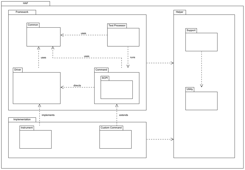
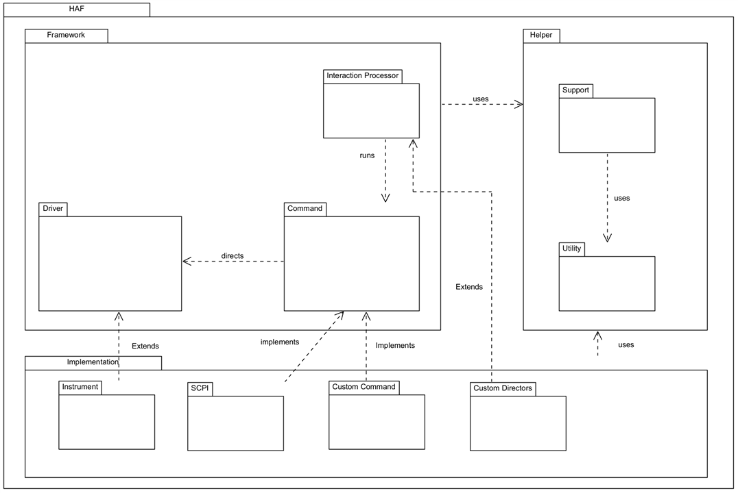
I usually find that there are helper classes that are independent of the main application but provide support for it, and classes that are purely reusable bits of utility code. These are best managed through their own packages rather than within the main application package(s.) As development progressed, I found a need to restructure the package dependencies and you can see this in the changes here:
| {gallery}Package Diagram |
|---|
|
Starting Package structure: As I originally conceived it |
|
Current Package structure: correct separation between the framework and the implementation packages |
In the framework code, the packages are represented as Project Virtual Folders: there are a lot more packages than shown above, but these are the main ones.
Class Diagram
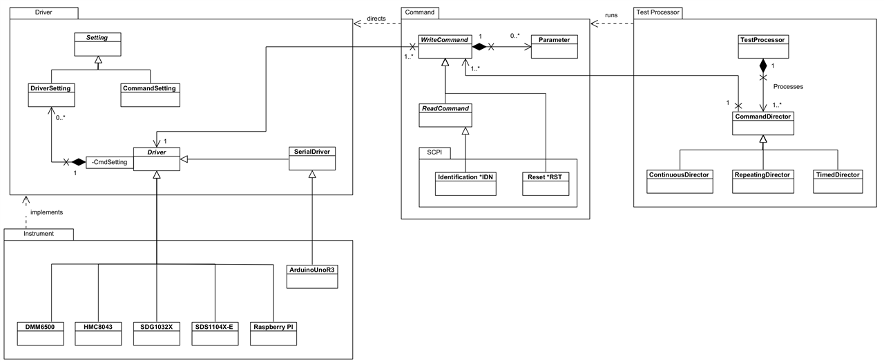
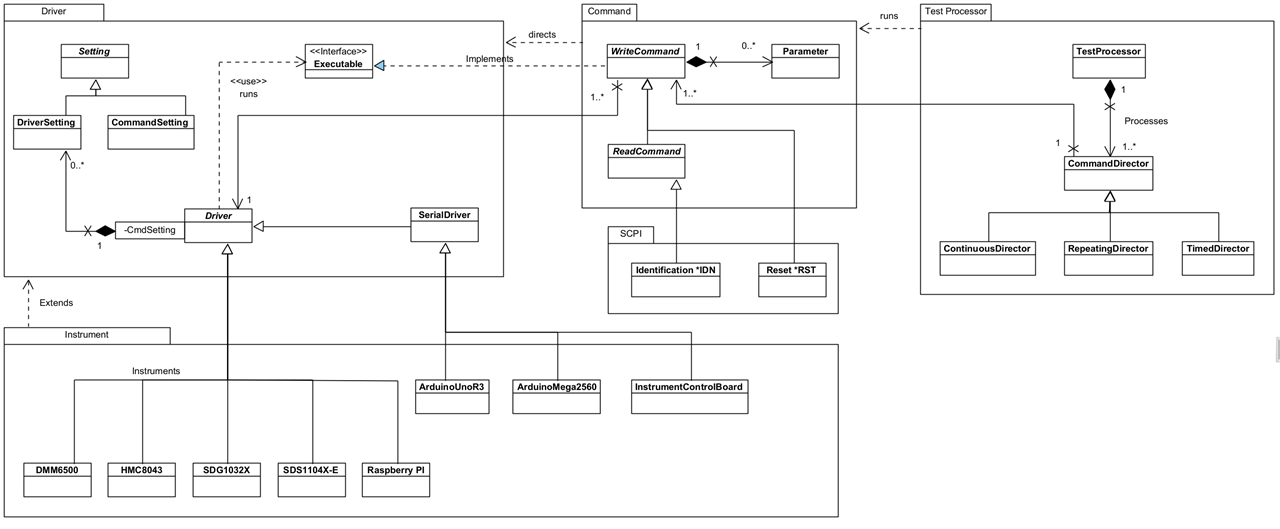
I identified a first cut of Classes from the requirements and captured those in a Class Diagram. During the development I realised that in spite of good intentions, I had introduced a cyclic dependency between Driver and Command, so I had to revisit this obviously. There ended up being more classes created, particularly in the Helper packages, but the core classes originally envisaged didn't change much. I'm hoping that what jumps out is that the framework, whilst offering a good set of features, is not particularly complex.
| {gallery}Class Diagram |
|---|
|
Starting Class Diagram: First cut of classes, not including those in the Helper packages which I hadn't really considered at this stage |
|
Current core classes: Driver now completely separated from Command via an interface, Executable. Helper classes not shown but there are a number of these. |
There's been some change here, mostly as part of the restructuring of Packages. The main change though has been in how Driver and WriteCommand interact. It became obvious that Driver would need to make callbacks on the Command in order to, for example, get the actual command string to send to an instrument. This created a circular dependency which I'm really not happy about (ever!) and the obvious fix was to use an Interface: the WriteCommand then implements (inherits in LabVIEW terms) that interface and can provide the necessary behaviour without tying Driver directly to an implementation. The dependencies remain one-way.
State Machine
Whilst developing the Framework, I realised that what I was developing was akin to a State Machine. Internally, it uses messages to signal the next step for processing which map nicely onto States:
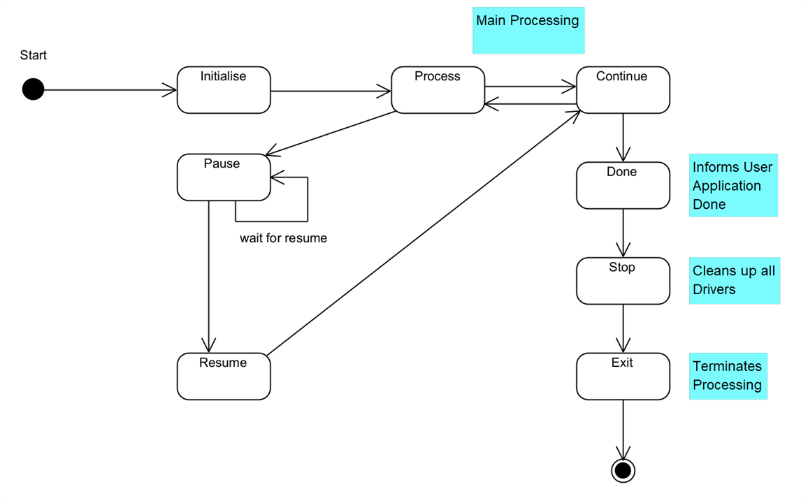
This shows the states that an interaction goes through whilst it is running. The Process State actually processes each Command Director and the Continue State determines whether the test has finished or not (as notified by the Command Directors.) The framework transitions processing between these two states until the Command Directors all report they are done. Pause and Resume are states that are initiated from a User Application.
To Sum Up
The design approach taken was model the Framework as classes in UML and iterate over that design as development progressed. I wasn't interested in trying to nail everything down from the start, not least because that never works, because a lot of decisions would come out of the development itself. I did have a good handle on what I was trying to achieve though and that worked out to be fairly stable.
Key Implementation Decisions
In this section, I want to describe some of the key LabVIEW features I used in creating the Framework. This isn't the totality of course, there are many elements of LabVIEW that have gone in to the implementation but these represent the important and interesting ones.
Object Oriented Programming in LabVIEW
Object Oriented Programming was used to develop the framework. It is worth reading this white paper to understand how LabVIEW implements this paradigm as there are differences to OO languages such as Java and C#. Given I'm new to LabVIEW some of the concepts weren't immediately obvious or understandable and required a bit of research in order to properly contextualise the information but was worth doing.
The main difference to be aware of is that natively, LabVIEW supports a by-value approach to OO and not a by-reference one, simply:
- By-value: when an object is passed to a VI, forks on a wire or tunnels into a construct, then a copy is made and any changes to attributes are on that copy only and only for as long as that copy exists.
- By-reference: when an object is passed to a VI, or a wire for the object instance is branched, then a reference to the object is passed and changes to attributes affect the originating instance and thus visible wherever it is used.
Why does that matter?
- By-value: If a copy of an instance is changed, then it may be necessary to synchronise that instance with the originating one or perhaps replace it altogether. If parallel processes are executing, both using an instance of the class which should be the same, how is that achieved - message passing, data queues…? It requires an awareness when programming of the implications of working on copies (by-value instances) and forgetting can introduce subtle bugs as I found with LabVIEW NXG (why hasn’t that data changed?) However, this is the native architecture of LabVIEW so is in coherence with the way it works and its highly parallelised execution. By-value prevents issues such as race conditions and deadlocks and means that LabVIEW can guarantee data integrity (but not data consistency without developer involvement!)
- By-reference: shared instances is the normal execution pattern used by OO languages and the pattern of thinking of programmers coming from those languages. It requires an acceptance and understanding of an application’s architecture when updating attributes of an instance in respect to the overall “where and when” that can happen in a program’s execution. Inherently, with multi-threaded, parallelised applications, issues such as race conditions and deadlocks raise their head; single threaded applications won’t suffer these issues of course. LabVIEW is highly parallelised so an acute awareness of this is required. It will imply that certain code execution paths, e.g. reading - updating - writing an attribute, needs to be atomic with respect to the whole application and thus blocking to other threads. That’s not something we really want to do lots of in LabVIEW programs. In any case, I suspect this approach will also introduce subtle bugs as anyone who has been involved in multi-threaded development can attest to.
It is possible to take a by-reference approach with LabVIEW as it provides mechanisms to do so and additionally installable packages can simplify that. The choice therefore isn’t just “by-value” because that’s what is available and clearly there are trade-offs to be made with either approach. There are numerous discussions of the pros-and-cons (hints in this thread) but I suspect that anyone who is experienced in OO will be able to make their own decision; as usual with engineers, there are supporters and detractors of both approaches.
Given this was about learning LabVIEW I stuck with its native by-value architecture.
Other differences worth being aware of:
- LabVIEW is strongly typed and does not support the concept of NULL. It's not possible to tell if an instance has been initialised with, say, a zero value for an attribute or purposefully set at zero - at least, not without additional code. The usefulness of NULL in OO crops up more often than you may think.
- There is no overloading of methods, all methods must have a unique name and any inputs and/or outputs don't form part of the method's identity. There is a mechanism called "Dynamic Despatching" which allows methods to be overridden and the correct one to be executed at runtime.
- LabVIEW definitely has some functionality supporting reflection but it doesn't appear to be extensive. I used it in a number of places in the Framework, both upcasting and down casting objects. Reflection is useful where dynamic instantiation of test devices or commands is required at runtime from, say, a configuration file (think test scripting rather than UI initiation.) Also, think Factory Pattern. I don't believe there is an equivalent of something like "isTypeOf" for determining what is being used at runtime, but a failed down- or up-cast would tell you it definitely wasn't in the class hierarchy of the class you are interrogating.
- There is no real concept of "Abstract" and any class can be instantiated. It would appear there is a view that creating a Class without any properties makes it abstract, but that seems wrong to me: an abstract class can, and often does, have properties that are inherited by subclasses. I think the argument goes that without properties, it's just a collection of VIs. It's not a massive issue of course because I just avoid instantiating anything that should be abstract.
- On the other hand, it is possible to have an abstract method. A method can be set to do nothing on a parent and a setting made for the method to force subclasses to override.
- Interfaces are available to use. A class can "inherit" (because that's how it's articulated in LabVIEW, rather than implement) multiple interfaces and then have to provide an implementation of the methods. The reason that interfaces are used with the term inherit is because they can actually carry implementation and not just define expected behaviour (they also can't carry state); this is promoted as a form of multiple inheritance which I suppose it is, but leads to some very complex inheritance graphs. The Framework uses an Interface to prevent a cyclic dependency between Driver and WriteCommand.
Messages, Notifications and Events
Communicating within the Framework and between the user Interaction Application and the Framework is accomplished through message queues and events. The Framework has its own message queue which is used to signal state transitions. The user application has a notification message queue which the framework uses to publish results whilst running. Actually there are two means of handling results: via a Results Notifier on the Notification Queue which allows for asynchronous processing, useful for long-running tests; or via a Results message on the Notification Queue which will build up and can be processed "en-masse" once the test has finished, useful for simpler short-running tests.
Whilst the application is running, Events are used from the user application to the Interaction Processor to signal directives - e.g. Pause, Resume, Stop and so on. The Interaction Processor acts on these at the end of a Processing Loop (see image in the Project Design section). The Interaction Processor can also send a Stop event to the user application when the test has finished: this allows the user application to take any appropriate action at the end of the test.
There's one more Event: Inject Command. Whilst the Interaction Processor is running it may be desirable to add additional Commands (Command Directors), e.g. with updated UI values perhaps, and this is achieved with this event. The new Command Directors are added to the end of the current set of Command Directors for processing.
It's worth mentioning the difference between Notifiers and Events as they seem similar. A producer raises a notification then carries on with what it is doing - whatever is waiting on the Notifier will do its thing as well. A producer raises an event and then carries on with what it is doing - whatever is registered to receive that event will do its thing as well. The big difference is that to act on a Notifier, a consumer has to be waiting for it (i.e. doing nothing); with an event, of course, the consumer could already be engaged with processing something, say other events. Clearly if your job is to process a result, then you need to wait for that result to come in.
Queued Message Handler Pattern
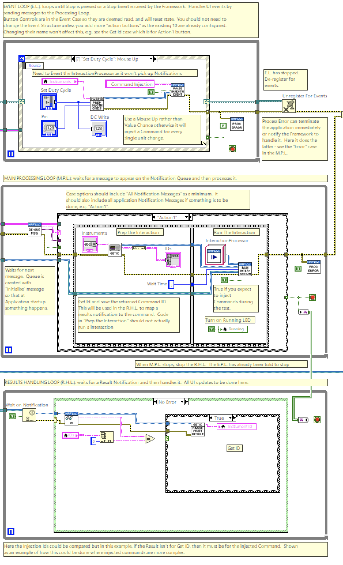
The implementation of the Framework and example Interaction Applications follow a Queued Message Handler pattern (the image is a portion of an example application.) This facilitates multiple sections of code running in parallel and sending data between them. Each section of code represents a task (e.g. acquiring data, logging data, user events) and is designed similarly to a state machine: the Framework uses an Event Handling Loop, handling Framework events, running in parallel to a Message Handling Loop, handling the state machine; the example applications use an Event Handling Loop (handling UI and Framework events), a Message Handling Loop (handling application states and messages from the Framework), and a Results Handling Loop (handling notifiers.)
More detail on the pattern can be read in the NI documentation.
Channel
LabVIEW follows a dataflow execution model which means that as soon data is available a section of code will run. It also means that at tunnels and wire forks, data values on that wire is copied. This can make it awkward to pass data around through sub-VIs and even across a block diagram in one VIs. It's part of the reason why resorting to local variables can be useful, but they have the potential to introduce their own problems (namely, race conditions if care isn't taken when updating/reading the values because of the parallel execution.)
A feature LabVIEW has is Channels which simplifies the data transfer between parallel running loops. Whilst data travels on wires in a synchronous manner (a source node produces the data when it finishes and passes it onto a sink node), data in a channel travels asynchronously and both node and sink can carry on executing, e.g. in a loop.
The example application uses a Tag Channel to pass the terminating condition of the Message Handling Loop to the terminating state of the Results Handling Loop - this can be seen in the image under Queued Message Handler. That way, when the MHL terminates, it can terminate the RHL at the same time. A Tag channel is like a variable and can carry a single value that can be written and read and is useful when you only care about the last value on the channel; there are other types of channels that suit other purposes.
More detail on Channels can be read in the NI documentation.
Global Variables in a LabVIEW-Safe Manner
As a general rule, it's not a great idea to use local or global variables in LabVIEW. The issue is that a LabVIEW application is highly parallelised and sections of code will run when they have the data available to do so. The use of dataflow helps control this by the developer ensuring that programs are written in such a way that data "arrives" at a piece of code when it should run in a sequence that makes sense for the program.
Clearly then, if code can run when it has the data available it can be tricky to ensure that values read from a variable are in a steady state, i.e. there isn't another piece of code in the application trying to update that variable. Having contention between reading and writing variables is called a race condition and is a common problem to overcome in parallelised code.
The problem comes in LabVIEW when you have values that are common across multiple VIs. To avoid the use of variables that value has to wired into, and across, all the VIs and Sub-VIs that need it (and some that don't but have to pass it on.) This is tricky and, frankly, not readily achievable. Therefore Global variables become a necessity in this situation. The Framework uses two Global Variables: one holds the Message Queues and one holds the Events that can be raised. Both these elements are used widely in the Framework and can be used by the Interacting Application if required. In order to ensure that race conditions don't occur, these variables are set by a Setup Framework VI that is the first thing to run; subsequently they are only ever read - their values never change.
There is a tip below that demonstrates the use of Global Variables.
Project Library
A Library is a useful means of organising related items, providing a namespace to qualify them in order to avoid any naming clashes with items that may be created by Interacting Applications that use the library. When a new item is created and given a name the library's name forms part of it (a qualifier) and this will distinguish it from other items in the project, but not the library, that have the same name. E.g. given a class called ResetCommand in library HAF, then the qualified name is actually HAF.ResetCommand (specifically: HAF.lvlib:ResetCommand.lvclass). This will ensure that any consuming application can contain an item that inadvertently (or otherwise) has the same name as a framework item without causing linking issues.
A library also allows me to set up access permissions for the contents of the library. For example, I can set public or private access rights to classes, or class methods, so that it is more obvious which ones should be used by an application and prevent access to those that are wholly internal to the framework. Libraries are created under the project, can be nested and a project can contain many libraries.
NI describes libraries in more detail in this article.
Development Approach
Project Folder Structure
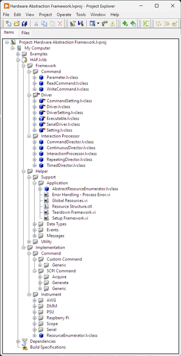
In a typical development scenario, the organisation of a project's files would occur through a number of folders on disk, e.g. \source; \bin; \libraries; \includes... With LabVIEW, there seem to be a number of possibilities and it can be confusing. Development interaction with a project is managed through the "Project Explorer" which displays the current project's organisation as either an "items" view or "Files" view:
| {gallery}LabVIEW's Project Explorer |
|---|
|
Project Explorer Items View: Shows the Project's items in a simplified structure. |
|
Project Explorer Files View: Shows the actual Project's files and folder structure. |
NI has this to say about managing applications using the Project Explorer. It discusses the use of folders for code organisation as a physical manifestation of the relationship between files and code in the application (as one typically does in other languages.) It's also very clear about managing projects and file locations through the Project Explorer so that the LabVIEW project can maintain the correct links across dependencies. In other words, don't move files manually on disk and hope that LabVIEW will recognise this when you next open the Project: it won't and you'll have to manually fix it.
From within LabVIEW, it is only possible to create a standard disk folder when saving a new item, e.g. a VI, using the OS save dialogue but there's no direct menu option. Creating it in this manner will show the new folder in the "Files" view. Any folder manually created outside Project Explorer, will not appear in the "Files" view, even if it resides inside a folder that does, until something is saved in it because, as mentioned, anything that happens outside LabVIEW isn't detected by the Project Explorer as there is no reference to it in the Project.
The document linked above discusses the use of Project Explorer for managing project organisation and with this it is possible to include an existing folder either as a "Folder (snapshot)" a.k.a. a Virtual Folder or a "Folder (Auto-Populating)":
- Virtual Folder: as the name suggests, it isn't actually a folder on disk, but a "construct" to allow items that are related to be kept together in the Items view. So it looks like a folder, but doesn't really exist on disk.
- Auto-Populating: this represents a more traditional folder on disk and LabVIEW will constantly monitor its contents and add them to the project. A Virtual Folder can be converted to an Auto-Populating folder which would then move all the items into that now existing disk folder from their current location.
More can be read about adding folders to a project in this "How-To" but I need to add some more about Virtual Folders because it can be quite confusing. It is possible with the Project Explorer to create a new Virtual Folder (for which a physical folder isn't created.) It is also possible to add a Folder (snapshot) for which a physical folder must exist for it to be added. When the "add Folder (snapshot)" option is used, a Virtual Folder is created in the project and any files within that snapshot folder also appear in the Virtual Folder as a one-time action. there is no actual link between the virtual folder and snapshotted folder: any items created within that virtual folder can be saved outside of the disk folder unless you specifically navigate to it as part of the save action. It can get quite confusing really!
Scanning the forums, more experienced LabVIEW developers seem to be mixed on the use of Auto-Populating folders. Some decry their use totally, others swear by them. However, Auto-Populating folders are not recommended when managing project libraries or classes and won't work for project templates. That makes it an easy decision to stick with Virtual Folders, for this project.
Final Virtual Folder Structure
Source Control with LabVIEW
I have used Git as the Source Control system. LabVIEW doesn’t integrate directly with Git so all source control activity needs to be managed outside of LabVIEW. It does work with source control systems that conform to Microsoft Source Control Interface, e.g. Subversion and Perforce and these tools can be integrated directly into LabVIEW. I use GitKraken as a client but it’s not important; I'm also didn't follow any fancy Git process as it's just me, so Master and Development branches. Thus, I can use LabView and Git together, just not from within the LabVIEW tool and there were some things that need to be done to facilitate that:
- Separate compiled code from other file types: for an insight, read this white paper. Essentially, VIs are a mix of text and binaries and that makes it harder for source control to work with them because unchanged parts of the application are recompiled anyway looking like a change. It's possibly more of an issue for Subversion or Perforce which requires a file to be "checked out" before it can be modified whereas Git will just create a new changed version. I'll cover this setup later.
- create and populate a suitable .gitignore file
- create and populate a suitable .gitattributes file
.gitignore
# Libraries
*.lvlibp
*.llb

# Shared objects (inc. Windows DLLs)
*.dll
*.so
*.so.*
*.dylib

# Executables
*.exe

# Metadata
*.aliases
*.lvlps
.cache/

# Not needed
*.bak*
.DS_Store
Thumbs.db
.gitattributes
Due to the way some LabVIEW files are constructed they contain both text and binary data. Additionally, Visual Paradigm files also need to be considered as binary. To ensure that Git doesn't mess this up treats these files as binary I added a .gitattributes file at the same level as .gitignore containing the following:
*.vi binary
*.vim binary
*.lvproj binary
*.lvclass binary
*.lvlps binary
*.aliases binary
*.lvlib binary
*.vit binary
*.ctl binary
*.ctt binary
*.xnode binary
*.xcontrol binary
*.rtm binary
*.vpp binary
*.afdesign
The "binary" attribute is actually a Macro Attribute: it combines together a number of single attribute settings against the file to ensure it is handled correctly.
Setting up for Reuse
I had to consider how to actually develop this framework. The intention is that it is reusable for future applications created in LabVIEW for testing my projects. I could just copy the code from a "library" directory on my hard drive/One Drive, or clone from GitHub but there's a great solution baked into LabVIEW: Project Templates. This allows a user to create a new project, based on a previously created one and which then LabVIEW sets up the new project with all the necessary elements to get started. It's possible to see this in action by creating a new project from the LabVIEW startup screen, and selecting a Template on the subsequent dialog.
The framework now works successfully as a Project Template folder and it is always available and up to date for consuming projects.
Possible Improvements
As I've developed this, I noted down things that I would look to improve as part of the next iteration. There's always the need to add in more commands but in terms of actual Framework functionality there are things I would revisit now I know a lot more about LabVIEW and its features
Driver Class
This class is overloaded in behaviour and whilst this isn't critical in terms of operation, refactoring might give some future flexibility. The image below shows the class with its properties (folders which contain Read/Write methods for the named property) and methods.
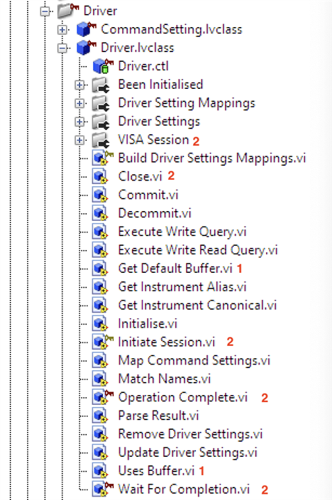
- I should create a subclass of Driver called BufferedDriver which holds functionality for instruments that can, or do, use a buffer for storing results (e.g. DMM6500.) The existing methods return default values which work for non-buffered instruments but require overriding when needed.
- The property and methods should be refactored to a DriverSession class (and probably subclasses) which deals directly with the appropriate protocol, e.g. USB, GPIB, Serial. This might also refactor out of the Framework the class SerialDriver.
Constants
Currently, the framework is holding Message Ids and Event Names as constants using a TypeDef. A typedef is similar to other languages and allows the creation of a new named type to be used in the application. This works, but isn't ideal; it was an approach I picked up before discovering/thinking about an alternate way of managing these via a Constants VI - see Tip 1 below. The problem with TypeDefs is if it changes, i.e. I add/remove a constant then whilst the structural change for the added value (e.g. a new String) is replicated across the using VIs, the actual Constant value isn't necessitating a visit to those VIs to fully update them.
In actual fact, during development, I only made one change to the constants so it wasn't an important change to make which is why it has been deferred.
Mapping Named Resources
In order to obtain a Driver instance for a named resource (attached instrument) there is an element of hard coding - taking a look at the Driver class image above, methods Get Instrument Alias and Get Instrument Canonical - needs a value returned by the method implementation on the Instrument (Driver has no hard coding.) It would be better if this could be picked up automatically from an environment configuration. Each instrument is detected by LabVIEW and there is access to attributes associated with that instrument; in fact, using NI-Max to configure instruments an alias can be given and these are stored in an XML file somewhere. I'm sure that could be read and it would obviate the need then to implement these methods every time a new instrument is added.
In reality, this is a minor point as instruments aren't something that come-and-go and apart from these two methods everything is automated. Take a look at these two VIs:
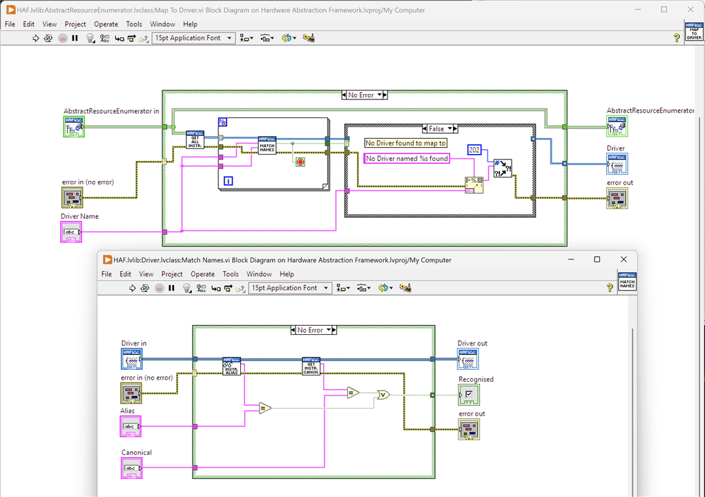
The upper VI is actually taking a selected Driver name - selected by a test user on the UI from a list automatically populated by the Framework - to an Instrument. It retrieves all Instruments attached to the system and looks to match either the alias or canonical name to the one selected by the user: if there is a match, then that is the concrete Driver instance selected for the test. It's a useful routine that avoids a user who creates a test having to code up the Driver to use because it can be identified at runtime.
I'm sure a bit more investigation will allow me to actually automate the Match Names process using the NI-Max XML file.
SCPI Commands
The framework is SCPI focussed right now because it's an easy win as it's a defined standard that all the instruments I own adhere to. I obviously haven't attempted to re-create the whole standard in code right away, I can develop commands as I need them. However, I'm starting to think over the possibility of combining WriteCommands and ReadCommands to something like a WriteReadCommand for when there is commonality in the actual SCPI command: often, a read version of a SCPI command is just the write version with a ? tagged on the end, e.g. MEAS:VOLT:DC tells the instrument to get a DC Voltage reading, and MEAS:VOLT:DC? actually retrieves the value from the instrument.
The standard can get quite complex so I need to spend some time looking more closely at the implications of this particular change. As it stands, the Framework works fine by having them separated and as the ones that currently exist are pre-defined it doesn't require a test creator to actually create them from scratch.
Background Execution of Tests
In some cases, it is possible to asynchronously call a VI to run it on a separate execution thread and not block the calling one. This would be useful for complex test applications that want to keep a main execution thread free to run, perhaps launching other tests in parallel. Unfortunately at the time of writing, LabVIEW doesn't support asynchronous calls to VIs that use Dynamic Dispatch terminals (parameters) which is something that all the methods on Classes do. It's not possible to switch to static terminals due to the way OO works in LabVIEW and the massive changes to the Framework that would have to be undertaken. This feature then will have to wait until such time as LabVIEW does support Dynamic Dispatch. See also Tip 3a below.
Results Exporter
I wanted to create a re-usable VI that allows results to be exported into a selectable format, e.g. CSV or XML. This is still on the cards as it's very useful but I just ran out of time.
Results Notifier
In the example applications, I've created a Notifier with a name and a ReadCommand as a passed parameter - it's used to send results back to the Interacting Application as they are produced.

This should be a helper VI as it's almost certainly going to be the standard way of creating this notifier
Tips
Here are some useful tips I've picked up along the way. I've also tried to summarise in a text and image form for those who don't like watching videos. I have a project in GitHub that contains all the VIs used in the tips to examine further: https://github.com/ad-johnson/LabVIEW_Tips (new window)
1. Using Constants
Constants are widely used in applications to avoid hard coding values. In a typical language, these would be added as variables at the start of the source code but in LabVIEW using local or global variables is discouraged due to the dataflow execution model and potential for race conditions. What's a good way of handling constants then?
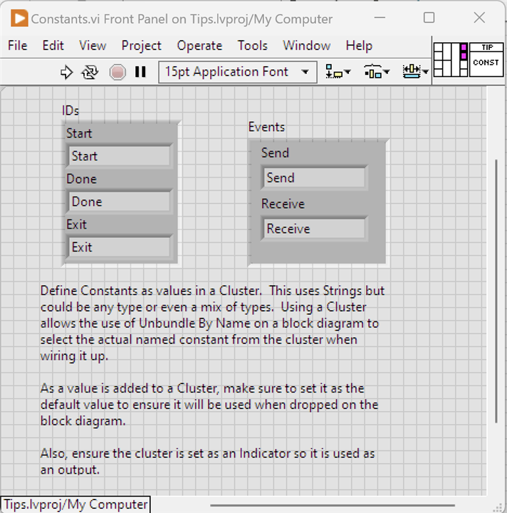
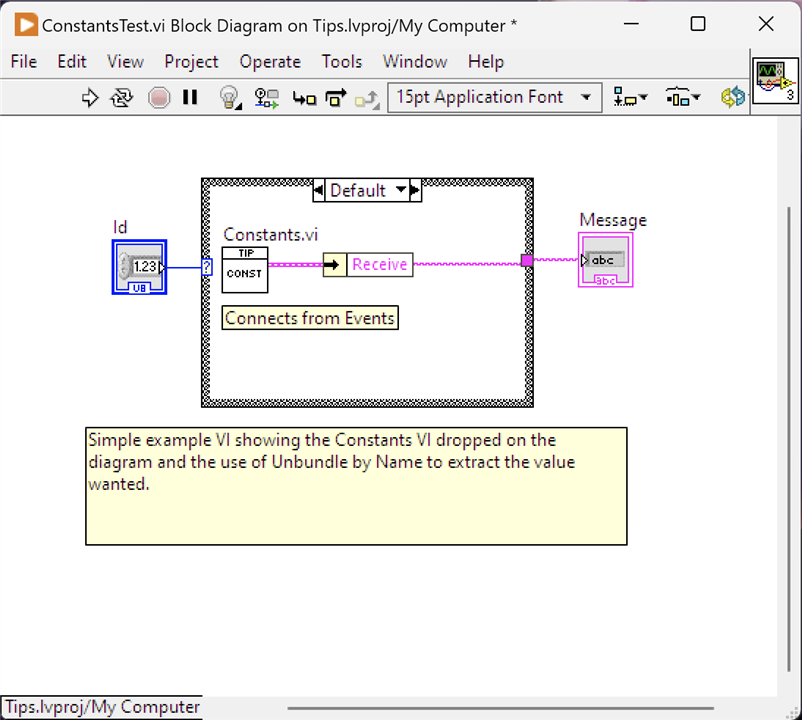
Create a VI and on the Front Panel drop a Cluster and add the constant values into it. These can be any type, I've used String for the example. Multiple Clusters can be used to represent groupings of values. In fact, multiple VIs could be created to hold different groupings if desired. Make sure these are set up as Indicators for output purposes and wire them to a Parameter Terminal; give the VI a decent icon. It's also worth ensuring that any value in the Cluster is set as the Default so that it will definitely carry the expected value when dropped on a Block Diagram. There is nothing to do on this VIs block diagram.
When the constant is to be used, second image, drop the Constant VI on to the block diagram and wire an Unbundle By Name Cluster function to the parameter terminal and select the named constant required.
Now, when a constant value needs changing it just needs updating in the Constant VI.
2. Creating a To Do List
Keeping track of code that needs revisiting, or tidying up, or even creating a list of tasks that have yet to be done often takes the form of a To Do list. Typically, inserted into comments with a common keyword to search for or used by the IDE to recognise. It's possible to achieve the same in LabVIEW.
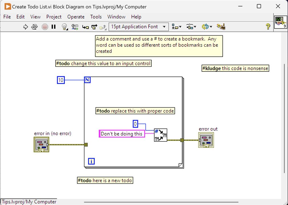
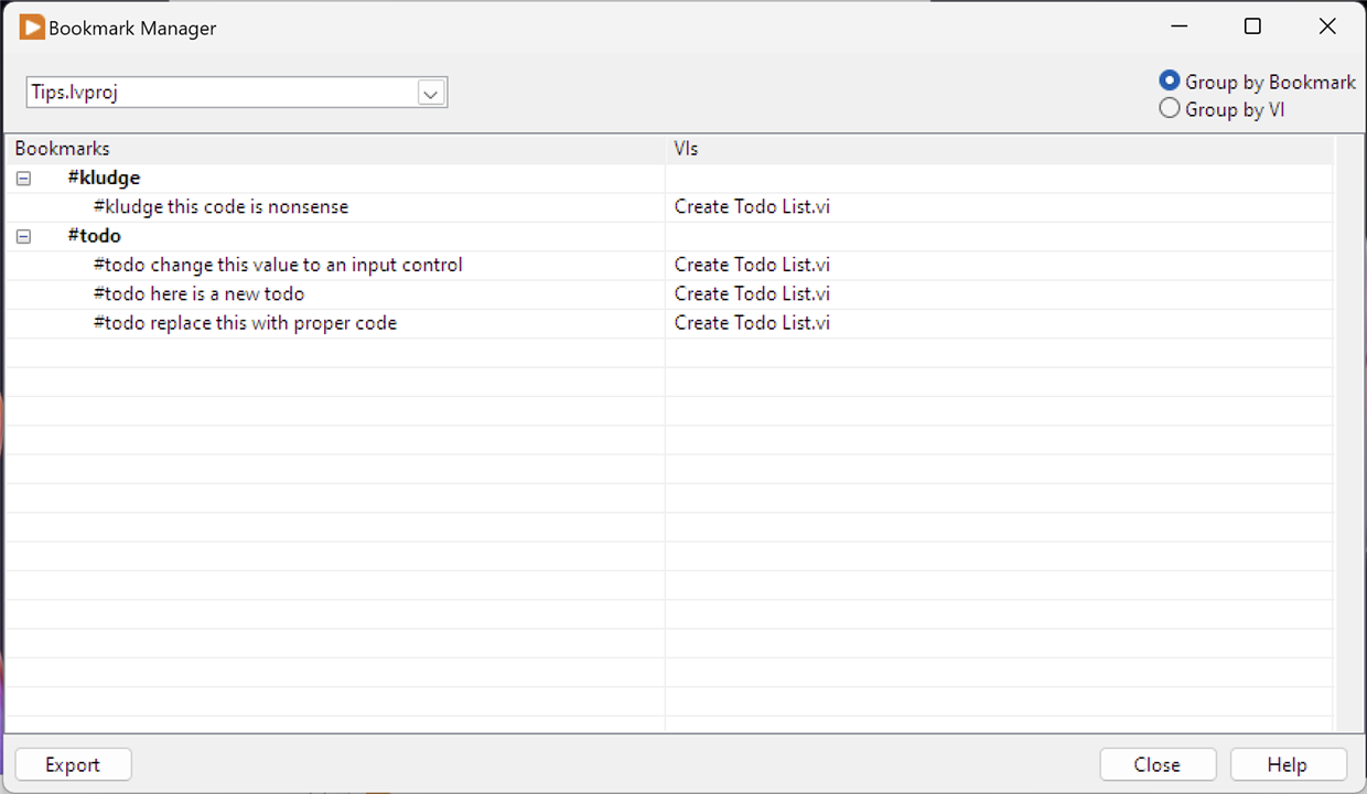
Creating a To Do list is as simple as tagging a common word in a comment. On this VI, I've used #todo. This creates a bookmark and all bookmarks can be seen by opening the Bookmark Manager from the View menu. Bookmarks are grouped together under the word chosen; to jump to the specific entry, just click on the VI name "Create Todo List.vi". You don't have to use #todo and any word can be used to create a bookmark, and I've added an extra example, #kludge.
3. Commenting Out Code - Variations
It's often necessary to quickly try out different bits of code. Typically, this is achieved by placing comments around the block of code so it isn't deleted, but it won't run either. Code commenting is (or was) often used during maintenance so that there is history of what used to be in place. LabVIEW doesn't have this sort of concept: whilst comments can be added, they are essentially just notes on the block diagram. However, there is a way.
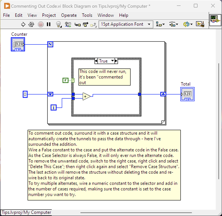
The way to stop code running and provide an alternative is to surround it with a Case Structure. LabVIEW will automatically move the code into a Case and create the necessary tunnels into and out of the Case Structure. Wire a Boolean Constant to the Case Selector and set it to False. Switching to the False case, enter the alternate code. As the Case Selector is always False, only the alternate code will run. The comment in the image explains how to remove the code you don't want as well as a means of trying multiple alternates.
3a Commenting Out Code - Disabling
As well as the approach in (3) for trying alternate code it is possible to disable code from running or, from what I can tell, being part of the compiled code base. This is achieved using a Disabled Structure around the code. Here's an example from the Framework:
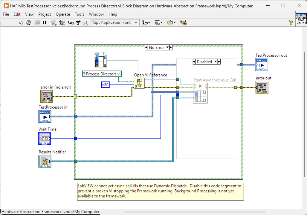
The intention of this VI was to allow a test to be run asynchronously in the background. That could provide benefits to a test application by not blocking any other execution paths whilst it is running. Unfortunately, in the current version of LabVIEW, the use of Dynamic Dispatch VIs in asynchronous code is not yet supported and as "Process Directors" and its Sub-VIs are Dynamic Dispatch VI this feature isn't available to the Framework yet. That left a broken VI, a non-running Framework and a choice: I could delete the VI and all would be well but I'd have to re-create it in future once supported; alternately, I could surround the offending code with a Disabled Structure which leaves the code in place but non-accessible. It also leaves the VI in a runnable state (i.e. non-broken) and the Framework can compile and be run.
4. Quick Delete of Node and Wiring
How annoying is it when you delete a node in LabVIEW and you're left with lots of hanging wires. Very - and a bit of a chore to delete them all. There is a better way
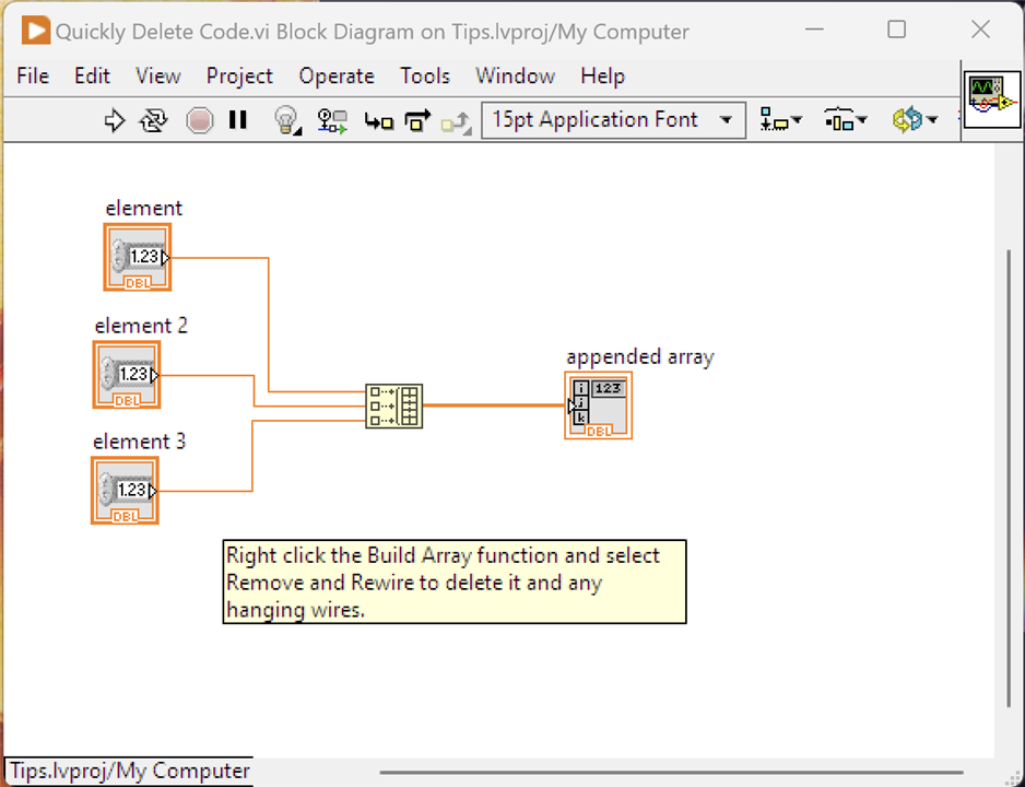
Select the Build Array function, right click and Remove and Rewire. This will delete all the wires you see as well as the Build Array Node leaving no hanging wires.
5. Using Globals
Sometimes it can’t be helped, you need to use a Global variable. In LabVIEW it is definitely frowned upon and for good reasons: it is way too easy to introduce race conditions in LabVIEW when you depart from the dataflow model and use variables, Global or Local. That doesn’t mean you can’t do it, it means you need to be very careful about updating and reading these. One good reason for the use of Global variables is where you have a situation that a particular piece of data is widely used across the application and without a Global, you would need to wire that data across multiple VIs, even those that don’t use it directly. It’s not a practical approach. The Framework does use two global variables but they are initialised when the framework starts up and from that point values are only read and never changed.
With that in mind, how do you create and use Global Variables - it’s a little different to defining Controls and Indicators and making local variables from them.
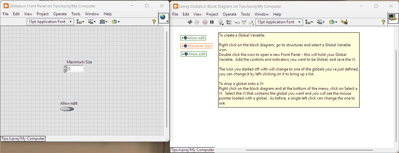
This tip doesn't really work with static images. I've tried to describe it in the comment on the Block Diagram. Note that the Front Panel IS NOT for that Block Diagram, it holds the globals which are define like any other Control or Indicator.
6. Colouring Front Panel Components
By default, the front panel looks very grey. It is possible to change the colours, but it isn't obvious.
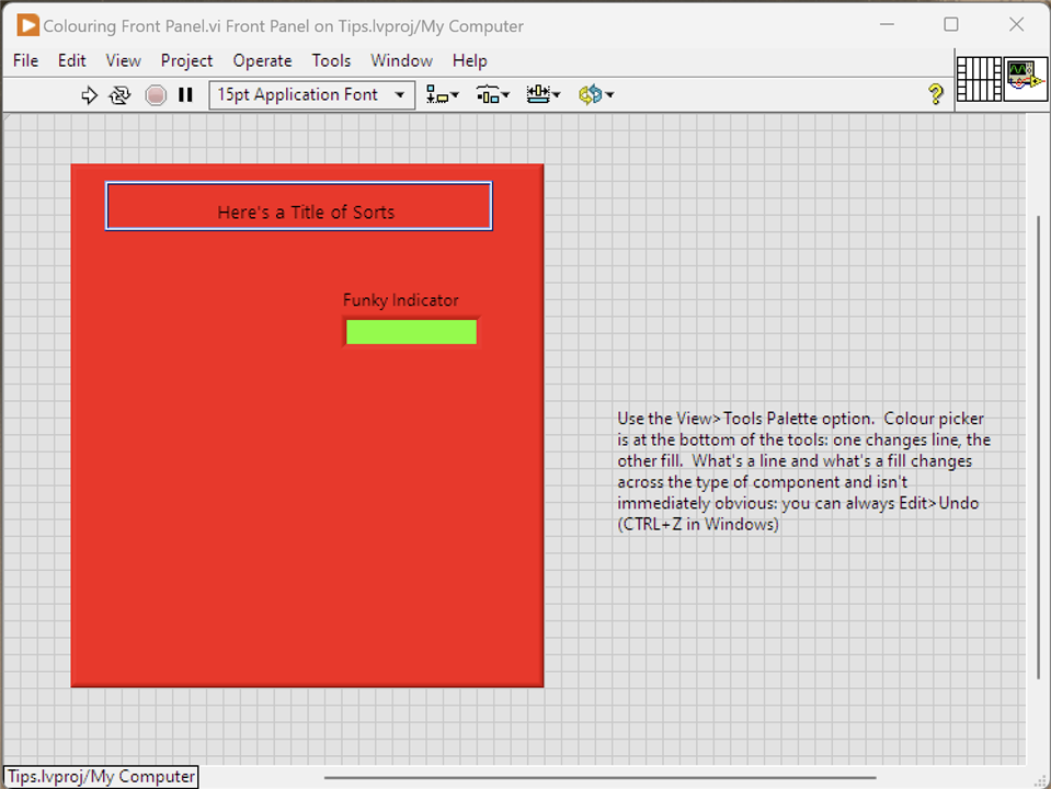
This is a lovely after image. Follow the instructions in the comment on the Front Panel to open the Tools Palette and colour away.
7. Determining What Errors LabVIEW can raise
How do you know what errors LabVIEW can raise in its function if you want to handle them in a more specific way? Simply, it isn't possible: they aren't documented anywhere and LabVIEW can probably raise thousands of different errors across its functions and VIs. Having said that, it may be possible to make a reasonable guess.

So with an Error Ring, it's possible to see the categories of errors LabVIEW can raise and within a category, the actual errors. It doesn't pin it to a specific function or VI but it may provide some pointers. Another tip is to try a test VI and force an error of the type you are interested in: place a probe on the error out wire and see what data travels it and pick up the code from there.
Summary: What I Learned
LabVIEW is an interesting language to learn and develop with. It is truly visual by which I mean at no point do you drop down into a textual code language to add functionality. Often, with visual languages, that visual element works great for the simplest of applications but as soon as anything slightly complex is required, native code has to be written. Not so with LabVIEW: it provides the necessary functionality on its visual elements such that it requires what I would call "tick box" configuration to get that element to do what is needed. The common code constructs such as looping and branching are catered for, although it can lead to some clumsy looking VIs - there's no nested-if capability or else-if capability for example. Even more complex algorithms are catered for, e.g. the use of Shift Registers for accumulating values through a loop. It would seem that over the years, the product has developed to cater for pretty much any development scenario - certainly I never found myself stuck for lack of a feature. The Framework and example applications are fairly complex but at the same time not particularly difficult to develop, although my IT experience would help a lot, and having some knowledge of LabVIEW NXG.
The way that programs are developed leads to very granular applications. VIs tend to be short bits of functionality and can then be embedded in other VIs. This makes them easy to create and debug because they are so well encapsulated and have a well defined interface, through the Controls and Indicator parameters (inputs and outputs respectively.) NI market LabVIEW as being suitable for non-programmers but I wouldn't be able to go that far - perhaps, it's suitable for engineers who can program but don't really need to. Certainly, I don't think someone who has had no contact with programming or even just superficial contact could grasp it. After all, programming isn't so much in knowing the language syntax it's about knowing how to use it and thinking logically to break down the steps.
Pretty much the hardest thing I had to grapple with was to remember the dataflow and data copy model that LabVIEW works with. Having been so used to a by-reference model, and a mostly sequential (i.e. not multi-threaded) programming approach, it was easy for me to get caught out by code not working as I expected. Nearly every debugging problem I came across ended up with an "of course, dataflow..." realisation.
It's very useful to now have this Framework in LabVIEW that I can run on my laptop on my workbench. It's easy to connect up the necessary instruments via a USB hub and I can also control serial devices assuming I have an application running on them that will understand the commands sent. I'm not even tied into a SCPI interaction.


