element14 Community
element14 Community
    Register Log In
  • Site
  • Search
  • Log In Register
  • About Us
  • Community Hub
    Community Hub
    • What's New on element14
    • Feedback and Support
    • Benefits of Membership
    • Personal Blogs
    • Members Area
    • Achievement Levels
  • Learn
    Learn
    • Ask an Expert
    • eBooks
    • element14 presents
    • Learning Center
    • Tech Spotlight
    • STEM Academy
    • Webinars, Training and Events
    • Learning Groups
  • Technologies
    Technologies
    • 3D Printing
    • FPGA
    • Industrial Automation
    • Internet of Things
    • Power & Energy
    • Sensors
    • Technology Groups
  • Challenges & Projects
    Challenges & Projects
    • Design Challenges
    • element14 presents Projects
    • Project14
    • Arduino Projects
    • Raspberry Pi Projects
    • Project Groups
  • Products
    Products
    • Arduino
    • Avnet Boards Community
    • Dev Tools
    • Manufacturers
    • Multicomp Pro
    • Product Groups
    • Raspberry Pi
    • RoadTests & Reviews
  • Store
    Store
    • Visit Your Store
    • Choose another store...
      • Europe
      •  Austria (German)
      •  Belgium (Dutch, French)
      •  Bulgaria (Bulgarian)
      •  Czech Republic (Czech)
      •  Denmark (Danish)
      •  Estonia (Estonian)
      •  Finland (Finnish)
      •  France (French)
      •  Germany (German)
      •  Hungary (Hungarian)
      •  Ireland
      •  Israel
      •  Italy (Italian)
      •  Latvia (Latvian)
      •  
      •  Lithuania (Lithuanian)
      •  Netherlands (Dutch)
      •  Norway (Norwegian)
      •  Poland (Polish)
      •  Portugal (Portuguese)
      •  Romania (Romanian)
      •  Russia (Russian)
      •  Slovakia (Slovak)
      •  Slovenia (Slovenian)
      •  Spain (Spanish)
      •  Sweden (Swedish)
      •  Switzerland(German, French)
      •  Turkey (Turkish)
      •  United Kingdom
      • Asia Pacific
      •  Australia
      •  China
      •  Hong Kong
      •  India
      •  Korea (Korean)
      •  Malaysia
      •  New Zealand
      •  Philippines
      •  Singapore
      •  Taiwan
      •  Thailand (Thai)
      • Americas
      •  Brazil (Portuguese)
      •  Canada
      •  Mexico (Spanish)
      •  United States
      Can't find the country/region you're looking for? Visit our export site or find a local distributor.
  • Translate
  • Profile
  • Settings
Single-Board Computers
  • Products
  • Dev Tools
  • Single-Board Computers
  • More
  • Cancel
Single-Board Computers
Forum 5V UARTs on SBCs?
  • Blog
  • Forum
  • Documents
  • Files
  • Members
  • Mentions
  • Sub-Groups
  • Tags
  • More
  • Cancel
  • New
Join Single-Board Computers to participate - click to join for free!
Actions
  • Share
  • More
  • Cancel
Forum Thread Details
  • Replies 28 replies
  • Subscribers 60 subscribers
  • Views 2876 views
  • Users 0 members are here
  • uart-to-usb
  • noftdi
  • uart
  • no-ftdi
  • usb-to-uart
Related

5V UARTs on SBCs?

shabaz
shabaz over 9 years ago

Hi!

I'm thinking of turning this project into a PCB:

Building a USB UART Serial Adapter


As part of that, I thought a few bits of functionality could be added at low cost:

(a) an MSP430 programmer

(b) perhaps a voltage monitoring capability since there is an ADC on the MCP2221


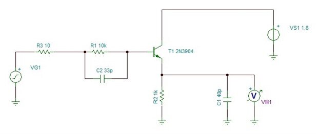
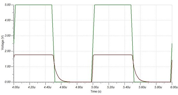
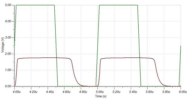
However, I wanted it to be a super-simple project. The current project uses jumpers to select 5V or 3.3V logic level UARTs. One solution could be

a switch, but it would be nice to not have a switch either.

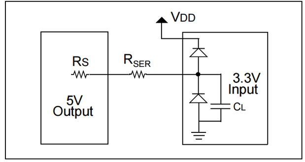
To eliminate that, I'm thinking of making the Rx pin 5V tolerant, but leave the Tx pin at 3.3V logic levels. This should therefore be compatible with any boards

that use 3.3V levels, but also the 5V Arduino Uno (it should be fine with 3.3V logic level input according to the ATmega datasheet).

(I'll also make it somewhat tolerant to accidentally swapping round of Rx and Tx).


My question is, does anyone know, are there any popular 5V boards that would not be OK with 3.3V logic level?


(I know now there are 1.8V boards too, like the Odroids, but that is a complication too far, so this board will only handle 3.3V and have the tolerance for 5V).


Thanks!

  • Sign in to reply
  • Cancel

Top Replies

  • rachaelp
    rachaelp over 9 years ago +3
    You can get bi-directional level translator IC's that will run either side from differing voltages. You could use one of these with one side powered from your circuit and the other side either powered…
  • jc2048
    jc2048 over 9 years ago in reply to shabaz +3
    It's not "totally insane", it just falls in that grey area between hacking and good design. Reverse biassed diodes are a very common way to protect the input/output from ESD [electro-static discharge]…
  • dougw
    dougw over 9 years ago in reply to shabaz +2
    Lets see - if going through hole is like going from touch screen back to pushbutton then wire-wrap must be like rotary dial. (point-to-point wiring would be like switchboard phoning?)
Parents
  • gihu
    gihu over 9 years ago

    CP2103 fits except for the encapsulated...

    Powered from USB, and taking VCC from the board (arduino, RPi, BBB...) to connect it to the VCCIO of the CP2103

    • Cancel
    • Vote Up +1 Vote Down
    • Sign in to reply
    • Cancel
  • shabaz
    shabaz over 9 years ago in reply to gihu

    Hi gihu!


    Very nice part. I should add it to the list here, it looks closely related to the CP2102 (I think the main difference is the EPROM on the 2103 vs the PROM on the 2102, but I need to read the datasheet more thoroughly).

    Unfortunately as you say, the package is the thing that doesn't fit. The through-hole requirement is quite limiting. I also want to avoid having the extra wire if possible, not too sure yet until I try it out.

    With a 3.3V logic out it is ok for 3.3V and 5V UARTS (perhaps not some older SBCs if the 5V levels are not compatible : ( but hoping to just heavily restrict current to try to make it safe for 1.8V UARTs too (no idea yet if this is practical, need to do some sums), also making it safe for both boards if RX/TX are accidentally swapped. The receive side just needs to be tolerant, which is easier to accommodate.

    It is only for development purposes, not production, so I don't overly mind if it doesn't work at high bitrates or with all historical boards. This way I can stick to through-hole parts entirely I think, and have something that doesn't need thinking before connecting. And maybe a proto area, so people can customize or add their own functionality (since there is I2C and ADC capability on the MCP2221), or the RS232 capability that Doug suggests, since that would be handy too. Example documented adaptations for RS232, MIDI etc would be cool.

    • Cancel
    • Vote Up +1 Vote Down
    • Sign in to reply
    • Cancel
  • shabaz
    shabaz over 9 years ago in reply to shabaz

    This is the kind of thing I'm envisioning (replace the text 5V with 3.3V, and the text 3.3V with 1.8V). I was just trawling the Internet to see if I could find any supporting docs to determine if it isn't totally insane.. This is from a Microchip doc (PDF).

    It might be an over-assumption that the diodes will be present. I can test it with some example 1.8V UART SBCs to see what the trend is in I/O pad design on ICs (because usually the UART will also be configurable as an I/O pin on application processors I think). If it works, then we'll have a USB-serial that needs no thought when plugging into 5V, 3.3V or 1.8V boards.

    image

    EDIT: Also considering the opto-isolation part, combined with the above. Together there would be the best of both worlds. It would be really nice to have it opto-isolated from the PC.

    • Cancel
    • Vote Up +1 Vote Down
    • Sign in to reply
    • Cancel
  • jc2048
    jc2048 over 9 years ago in reply to shabaz

    It's not "totally insane", it just falls in that grey area between hacking and good design.


    Reverse biassed diodes are a very common way to protect the input/output from ESD [electro-static discharge] but they aren't the only way so you are maybe taking a bit of a gamble (though probably not much of one). I don't know very much about IC design, but as I understand it the metal-contact diodes are essentially free because they use the metalisation layers that distribute the power and don't require extra processing steps. They're also nice because they are fast, but also have low capacitance and hardly affect the signals when they're not operating. So I think the manufacturers would need good reasons not to use them, which would only apply to more specialised chips where they might want to operate very fast, or have very low input leakage, or whatever. Or, of course, in a situation where an input is designed to tolerate more than the supply voltage.


    Manufacturers are [understandably] nervous of you operating outside the rails because the CMOS process can latch up. If you raise the input above the rail, you get what is effectively a 4-layer structure like an SCR that will latch on until the power is removed. If what's driving the input can supply enough current then it will permanently damage the chip. Again, I'm a bit hazy about this, but I think it might be a diode drop above, so the Schottky protection diode will come in before the latch-up occurs and save the day, but only if the current is modest. It's also complicated because the IC is a circuit and, as with any other circuit, there's no such thing as a perfect ground or supply rail, so with only a couple of hundred millivolts in hand it doesn't take much in the way of ground bounce or noise spikes on the supply to compromise that. 

    • Cancel
    • Vote Up +3 Vote Down
    • Sign in to reply
    • Cancel
  • jc2048
    jc2048 over 9 years ago in reply to jc2048

    If you're prepared to use the target supply and some transistors there are various ways to do the level translation (so you don't have to use one of these new-fangled IC thingummibobs). Most obvious is a pair of transistors as switches, giving a double inversion. Another possibility, which I thought I'd try simulating, is an emitter follower like this:


    image


    The schematic is drawn in TI's Spice simulator. [Just happens to be what I'm using at the moment. LT also provide a perfectly good simulation tool; I'm not making a case for one or the other, or indeed any other Spice simulation tool.] The voltage generator is a 5V square wave at 1MHz with 25nS edges. The 10 ohm resistor is my (very crude) model of the output FETs in the UART. C1 represents the parasitic capacitance of the input pin on the receiver, the PCB track and a (very minimal - couple of centimetres) piece of wire for the connection. Transient simulation looks like this:


    image


    That's equivalent to 2 MBits/s, so would be fine for 115200. I was looking at it that fast because I got sidetracked into examining the effect of the speed-up capacitor (C2) and how much value it adds [whether it might be a marginal improvement or a significant one].


    This is the simulation with C2 removed, so it does have a significant effect at higher speeds, but probably isn't necessary at 115200:


    image


    Where the circuit falls down (other than needing a supply from the target, which you were trying to avoid) is in the poor drive of the output capacitance. Even with just 40pF the output waveform is unbalanced. With 400pF [an additional couple of meters of cable] we get this, which would be useless at 2 Mbaud, though it might work for 115200.


    image

    • Cancel
    • Vote Up +2 Vote Down
    • Sign in to reply
    • Cancel
  • shabaz
    shabaz over 9 years ago in reply to jc2048

    Hi Jon,


    I think it's a good idea to use BJTs in this design, easy to find in through-hole of course, and cheap.

    Definitely the Rx side will, to implement the voltage tolerance to allow interop for 1.8V logic through to 5V logic.


    The latch-up is a concern, as you say maybe it is an over-assumption that the I/O pads will always have the diodes present.

    But I am trying to do everything possible to avoid having the extra wire, or switches.. I may give up though if it seems too risky -

    but willing to sacrifice a test Odroid if that's what it takes! : (

    I just don't have many 1.8V SBCs here to experiment with.

    I wonder if I combine the current limiting and use something similar to what you've simulated to provide a (say) 2.3V logic level, then

    I'll avoid latch-up at 1.8V for any devices which do not have the diodes in their pads, yet still be compatible with any recent 5V UARTs.


    Interesting how a on-the-surface simple thing like a USB-Serial adapter can get awkward very quick once a few restrictions

    are placed on the design. I'd initially expected to not provide 1.8V capability, but I think I cannot avoid it now since it is becoming more prevalent

    in SBCs.

    • Cancel
    • Vote Up +2 Vote Down
    • Sign in to reply
    • Cancel
  • jc2048
    jc2048 over 9 years ago in reply to shabaz

    As to the real dangers of latch-up, I think you need the advice of someone who understands chip design. My knowledge is just old bits and pieces of the sort that you accumulate over the years. It's possible that they've found ways to mitigate the problem with the lower voltage logic - nowadays it's possible to have many more processing steps than were once economic, so maybe they can create structures where the latch-up happens at a much higher voltage. I still try to avoid excessive levels of overshoot, which is one area where it was sometimes a problem, but maybe I'm living in the past.


    If you think the receiver is always going to be operating with TTL levels, then you could just limit the tx signal to about 2V. A simpler way to do that than a transistor is a diode clamp:


    image


    image

    That suffers a little from the same problem as the transistor (charge storage slowing things down), so I though I'd try out the speed-up cap again (sorry, bear with me, curiosity beckons). This time we need to 'empty' all three diodes


    image


    now it's fast [small-signal diodes can really whizz along if you give them a bit of a nudge], but getting a bit silly in your case where you don't need the speed


    image


    As with the transistor, it's not going to drive very well - for good drive you need a balanced [active] output and to start considering termination for longer cables.


    Did I mention that I'm really into simulation? I'm like a child in a sweetshop with this new-found toy.

    • Cancel
    • Vote Up +1 Vote Down
    • Sign in to reply
    • Cancel
  • shabaz
    shabaz over 9 years ago in reply to jc2048

    Hi Jon!

    We're thinking along the same lines : ) I too was experimenting with speedup using capacitors, although as you say it might be unnecessary. I think from memory the typical UART state machines use a 16x clock (I could be wrong), so there is 1/16 of 1/115200 that I can afford to have in the undefined voltage region.

    I think I'm nearing into a design now, but I will do some tests/measurements on some of the popular boards, just to feel comfortable that the final selected values are likely to work with all popular boards and will be safe to accidentally have swapped around indefinitely.

    I can't wait to try it out, hopefully over the weekend!

    • Cancel
    • Vote Up 0 Vote Down
    • Sign in to reply
    • Cancel
  • jc2048
    jc2048 over 9 years ago in reply to shabaz

    Traditional UARTs were 16x and sampled somewhere in the middle. Your critical edges are on the start bit because they are going to be the reference for the timing of the sampling. I have a vague idea people subsequently developed schemes to sample more than once and do majority voting to avoid the obvious problem of a short supply glitch changing a bit.


    The PIC UARTs allow for x4, x16 and x64 (not all devices do all of those). The x4 rate accomodates the faster baud rates where they are getting close to the system clock rate. Not sure where it samples - I'd go for the clock cycle after the centre point if it were me designing it.  Presumably the Atmel parts on Arduinos would be similar. So you have a bit of lattitude at the edge, but not too much (if you want to cater for very fast baud rates).


    Have fun with the experimenting. Alternative clamps you might try would be a 2V zener diode or a red LED.

    • Cancel
    • Vote Up +1 Vote Down
    • Sign in to reply
    • Cancel
Reply
  • jc2048
    jc2048 over 9 years ago in reply to shabaz

    Traditional UARTs were 16x and sampled somewhere in the middle. Your critical edges are on the start bit because they are going to be the reference for the timing of the sampling. I have a vague idea people subsequently developed schemes to sample more than once and do majority voting to avoid the obvious problem of a short supply glitch changing a bit.


    The PIC UARTs allow for x4, x16 and x64 (not all devices do all of those). The x4 rate accomodates the faster baud rates where they are getting close to the system clock rate. Not sure where it samples - I'd go for the clock cycle after the centre point if it were me designing it.  Presumably the Atmel parts on Arduinos would be similar. So you have a bit of lattitude at the edge, but not too much (if you want to cater for very fast baud rates).


    Have fun with the experimenting. Alternative clamps you might try would be a 2V zener diode or a red LED.

    • Cancel
    • Vote Up +1 Vote Down
    • Sign in to reply
    • Cancel
Children
No Data
element14 Community

element14 is the first online community specifically for engineers. Connect with your peers and get expert answers to your questions.

  • Members
  • Learn
  • Technologies
  • Challenges & Projects
  • Products
  • Store
  • About Us
  • Feedback & Support
  • FAQs
  • Terms of Use
  • Privacy Policy
  • Legal and Copyright Notices
  • Sitemap
  • Cookies

An Avnet Company © 2025 Premier Farnell Limited. All Rights Reserved.

Premier Farnell Ltd, registered in England and Wales (no 00876412), registered office: Farnell House, Forge Lane, Leeds LS12 2NE.

ICP 备案号 10220084.

Follow element14

  • X
  • Facebook
  • linkedin
  • YouTube