element14 Community
element14 Community
    Register Log In
  • Site
  • Search
  • Log In Register
  • Community Hub
    Community Hub
    • What's New on element14
    • Feedback and Support
    • Benefits of Membership
    • Personal Blogs
    • Members Area
    • Achievement Levels
  • Learn
    Learn
    • Ask an Expert
    • eBooks
    • element14 presents
    • Learning Center
    • Tech Spotlight
    • STEM Academy
    • Webinars, Training and Events
    • Learning Groups
  • Technologies
    Technologies
    • 3D Printing
    • FPGA
    • Industrial Automation
    • Internet of Things
    • Power & Energy
    • Sensors
    • Technology Groups
  • Challenges & Projects
    Challenges & Projects
    • Design Challenges
    • element14 presents Projects
    • Project14
    • Arduino Projects
    • Raspberry Pi Projects
    • Project Groups
  • Products
    Products
    • Arduino
    • Avnet Boards Community
    • Dev Tools
    • Manufacturers
    • Multicomp Pro
    • Product Groups
    • Raspberry Pi
    • RoadTests & Reviews
  • Store
    Store
    • Visit Your Store
    • Choose another store...
      • Europe
      •  Austria (German)
      •  Belgium (Dutch, French)
      •  Bulgaria (Bulgarian)
      •  Czech Republic (Czech)
      •  Denmark (Danish)
      •  Estonia (Estonian)
      •  Finland (Finnish)
      •  France (French)
      •  Germany (German)
      •  Hungary (Hungarian)
      •  Ireland
      •  Israel
      •  Italy (Italian)
      •  Latvia (Latvian)
      •  
      •  Lithuania (Lithuanian)
      •  Netherlands (Dutch)
      •  Norway (Norwegian)
      •  Poland (Polish)
      •  Portugal (Portuguese)
      •  Romania (Romanian)
      •  Russia (Russian)
      •  Slovakia (Slovak)
      •  Slovenia (Slovenian)
      •  Spain (Spanish)
      •  Sweden (Swedish)
      •  Switzerland(German, French)
      •  Turkey (Turkish)
      •  United Kingdom
      • Asia Pacific
      •  Australia
      •  China
      •  Hong Kong
      •  India
      •  Korea (Korean)
      •  Malaysia
      •  New Zealand
      •  Philippines
      •  Singapore
      •  Taiwan
      •  Thailand (Thai)
      • Americas
      •  Brazil (Portuguese)
      •  Canada
      •  Mexico (Spanish)
      •  United States
      Can't find the country/region you're looking for? Visit our export site or find a local distributor.
  • Translate
  • Profile
  • Settings
BeagleBoard
  • Products
  • Dev Tools
  • Single-Board Computers
  • BeagleBoard
  • More
  • Cancel
BeagleBoard
Forum PocketBeagle with Midas LCD
  • Blog
  • Forum
  • Documents
  • Quiz
  • Polls
  • Files
  • Members
  • Mentions
  • Sub-Groups
  • Tags
  • More
  • Cancel
  • New
Join BeagleBoard to participate - click to join for free!
Actions
  • Share
  • More
  • Cancel
Forum Thread Details
  • State Suggested Answer
  • Replies 7 replies
  • Answers 4 answers
  • Subscribers 98 subscribers
  • Views 1089 views
  • Users 0 members are here
  • i2c
  • bbb
  • character lcd
Related

PocketBeagle with Midas LCD

chrischristian14
chrischristian14 over 5 years ago

Hi There,

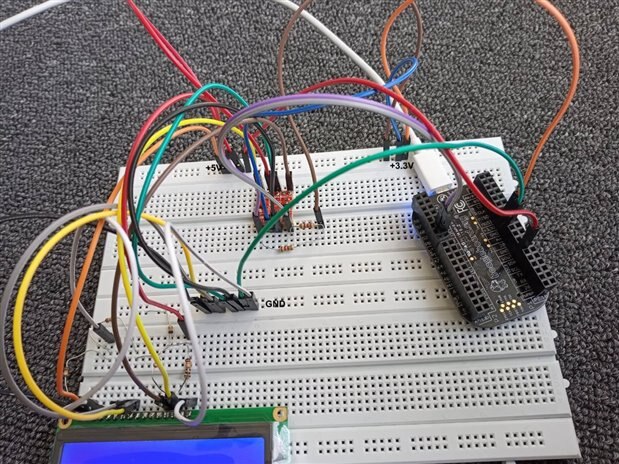
I am trying to get Midas LCD (http://www.farnell.com/datasheets/2825693.pdf?_ga=2.133739021.2051231456.1578547647-151509622.1578547647 ) working with pocket beagle.

I have tried mainly three different configuration but none of them seem to work.

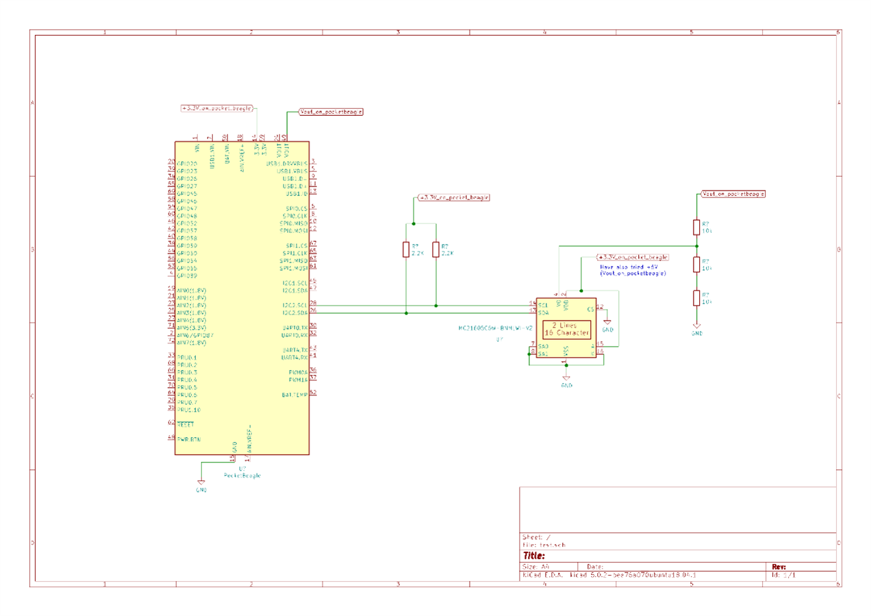
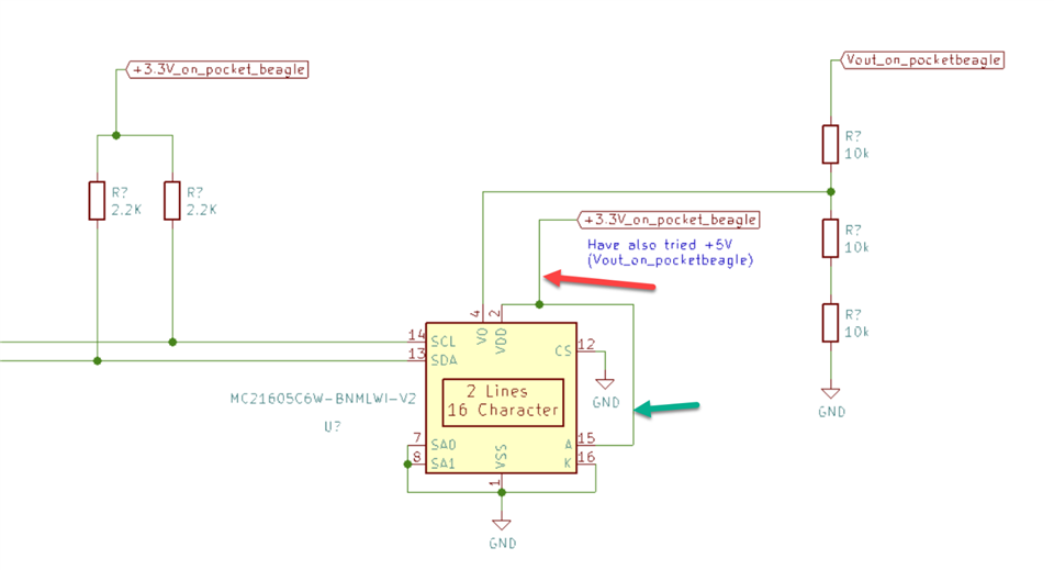
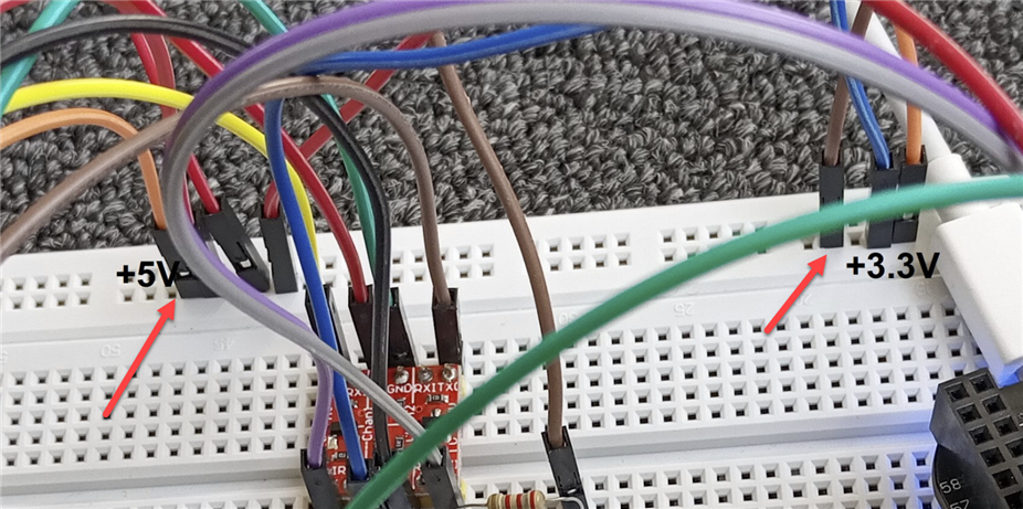
1) connected it exactly as per the datasheet, powering the VDD with +5V and connecting SDA and SCL through a 5v to 3v logic converter. VO is through a 10k-20k voltage divider.

2) connected it exactly as per the datasheet, powering the VDD with +5V and connecting SDA and SCL without the logic converter. VO is through a 10k-20k voltage divider.

3) connected it exactly as per the datasheet, powering the VDD with +3.3V and connecting SDA and SCL without logic converter. VO is through a 10k-20k voltage divider.

also Repeated 1) to 3) with VO = across 10K on voltage divider, VO = across 20K on voltage divider, VO = +3.3V and VO = +5V.


What am I missing ? I can't pickup anything on "i2cdetect - y -r 1", I have tried a +5V RTC module through logic converter on the same I2C and it works fine.

The LCD data sheet mentions pins IF0 and IF1 to set the LCD in i2c mode but there is no such pin in pin diagram ? I have contacted Midas but no reply !

has anyone ever used these LCDs ? any help will be appreciated.

Thanks,

Chris

  • Sign in to reply
  • Cancel

Top Replies

  • shabaz
    shabaz over 5 years ago in reply to chrischristian14 +1 suggested
    It's hard to follow the wiring, so I couldn't check that, but something looked odd in the areas marked with red arrows below. The left side says +5V, but the right side says +3.3V. However, most breadboards…
  • shabaz
    0 shabaz over 5 years ago

    Hi Chris,


    You have not mentioned pin 12, is that set low? Also, not shown on the datasheet, but a small capacitor near the display may be needed (e.g. 100nF).

    Pins 7 and 8 should be tied somewhere too, e.g. low.

    I've used several I2C displays in the Midas range, but unfortunately not the specific one you're using, so I'm not sure I can help much more though : (

    Usually the Midas datasheet is adequate, although there are sometimes bits of description (like the IF0 and IF1 you mention) that refer to the chip instead of the display, that's fairly expected of most of these displays though, they all have these slight issues in the documentation, but the main module pinout is reliable in the Midas datasheets from what I've seen.

    Regarding I2C, during your tests without a converter, since the PocketBeagle has 3.3V I/O, the I2C resistors you're using were pulled up to 3.3V and not 5V right?

    • Cancel
    • Vote Up 0 Vote Down
    • Sign in to reply
    • Verify Answer
    • Reject Answer
    • Cancel
  • chrischristian14
    0 chrischristian14 over 5 years ago in reply to shabaz

    Hi Shabaz,

    Yes, I have the pull ups on SDA and SCL to +3.3v on both times, when vdd=3.3v and when vdd=5v,

    CS is always pulled down. Backlight is also on, also tried with it having off.

    I'm not sure how to attach a picture to this but, there is no capacitor on the back of the LCD, all unpopulated footprints are either resistors or connectors (Rx or Jx , where x is a number)

    Thanks,

    Chris

    • Cancel
    • Vote Up 0 Vote Down
    • Sign in to reply
    • Verify Answer
    • Reject Answer
    • Cancel
  • shabaz
    0 shabaz over 5 years ago in reply to chrischristian14

    Hi Chris,


    The capacitor is something you can add externally to the board, close to it. If that still doesn't cause i2cdetect to find the board, then it sounds faulty.

    If you have a scope you could check to see that the SDA and SCL lines are being pulled low, and double-check the levels on the other wires (for example jumper wires sometimes are broken inside the shell), but apart from that I can't see what else could be causing the issue.

    You may need to attach some photos of your setup, just in case there's anything visible that looks odd.

    There's an editor tool to allow inserting photos inline into the discussion or comment, see here for details: How to Ask Questions using the Create Discussion tool

    • Cancel
    • Vote Up 0 Vote Down
    • Sign in to reply
    • Verify Answer
    • Reject Answer
    • Cancel
  • chrischristian14
    0 chrischristian14 over 5 years ago in reply to shabaz

    Please see  below, I have two of those LCDs and none of them are working, so I don't think they both are faulty out of the box. Are you suggesting putting capacitor across power lines on LCD ?

    btw: I am running the whole circuit from pocketbeagle, which runs from USB connected to PC, I have also tried using breadboard power supply but no difference.

    image

    Thanks,

    Chris C

    • Cancel
    • Vote Up 0 Vote Down
    • Sign in to reply
    • Verify Answer
    • Cancel
  • shabaz
    0 shabaz over 5 years ago in reply to chrischristian14

    Hi Chris,


    I think part of the issue is your connection to pin 15 - it needs a resistor at the green arrow location below, it is not optional. 100 ohms should be fine.

    Also, the datasheet says VDD has to be between 4.5 and 5V, so it shouldn't be connected to the 3.3V supply.

    Capacitor is needed on that rail (i.e. see red arrow below).

    If that doesn't work, you'd need to probe the I2C lines and check that the levels there look correct. Sometimes people do strange things like run extremely long cables, or have broken connections, so it needs to be probed.

    Also photos of your setup - just in case something else can be spotted.

    image

    • Cancel
    • Vote Up 0 Vote Down
    • Sign in to reply
    • Verify Answer
    • Cancel
  • chrischristian14
    0 chrischristian14 over 5 years ago in reply to shabaz

    Hi Shabaz,

    I don't have capacitor with me at home need to go back to Lab and will update you then, Midas got back to me and asked me to put the 100R on the backlight and also told me to try to increase the pull ups to 4.5K or more, I rearranged the circuit, tried with 100R and 10K pull ups but no joy, so I tried with logic level converter and 10K pull ups on the i2c lines on LCD side and 2.2K pull ups on the beagleboard side of the i2c lines, but still no joy.Please see the below image of the breadboard setup

    I will try the oscilloscope and capacitor from workshop and will update then.


    image

    Thanks,

    Chris C

    • Cancel
    • Vote Up 0 Vote Down
    • Sign in to reply
    • Verify Answer
    • Cancel
  • shabaz
    0 shabaz over 5 years ago in reply to chrischristian14

    It's hard to follow the wiring, so I couldn't check that, but something looked odd in the areas marked with red arrows below.

    The left side says +5V, but the right side says +3.3V. However, most breadboards have all of those sockets connected in one long horizontal line across the entire length of the breadboard. Is that not the case with the breadboard you're using?

    If the capacitor, and the suggestions from Midas do not help, then it is possibly a construction issue (e.g. faulty or broken wiring, or breadboard could be damaged). Needs multimeter and 'scope to test it all out.


    image

    • Cancel
    • Vote Up +1 Vote Down
    • Sign in to reply
    • Verify Answer
    • Reject Answer
    • Cancel
element14 Community

element14 is the first online community specifically for engineers. Connect with your peers and get expert answers to your questions.

  • Members
  • Learn
  • Technologies
  • Challenges & Projects
  • Products
  • Store
  • About Us
  • Feedback & Support
  • FAQs
  • Terms of Use
  • Privacy Policy
  • Legal and Copyright Notices
  • Sitemap
  • Cookies

An Avnet Company © 2025 Premier Farnell Limited. All Rights Reserved.

Premier Farnell Ltd, registered in England and Wales (no 00876412), registered office: Farnell House, Forge Lane, Leeds LS12 2NE.

ICP 备案号 10220084.

Follow element14

  • X
  • Facebook
  • linkedin
  • YouTube