element14 Community
element14 Community
    Register Log In
  • Site
  • Search
  • Log In Register
  • Community Hub
    Community Hub
    • What's New on element14
    • Feedback and Support
    • Benefits of Membership
    • Personal Blogs
    • Members Area
    • Achievement Levels
  • Learn
    Learn
    • Ask an Expert
    • eBooks
    • element14 presents
    • Learning Center
    • Tech Spotlight
    • STEM Academy
    • Webinars, Training and Events
    • Learning Groups
  • Technologies
    Technologies
    • 3D Printing
    • FPGA
    • Industrial Automation
    • Internet of Things
    • Power & Energy
    • Sensors
    • Technology Groups
  • Challenges & Projects
    Challenges & Projects
    • Design Challenges
    • element14 presents Projects
    • Project14
    • Arduino Projects
    • Raspberry Pi Projects
    • Project Groups
  • Products
    Products
    • Arduino
    • Avnet & Tria Boards Community
    • Dev Tools
    • Manufacturers
    • Multicomp Pro
    • Product Groups
    • Raspberry Pi
    • RoadTests & Reviews
  • About Us
  • Store
    Store
    • Visit Your Store
    • Choose another store...
      • Europe
      •  Austria (German)
      •  Belgium (Dutch, French)
      •  Bulgaria (Bulgarian)
      •  Czech Republic (Czech)
      •  Denmark (Danish)
      •  Estonia (Estonian)
      •  Finland (Finnish)
      •  France (French)
      •  Germany (German)
      •  Hungary (Hungarian)
      •  Ireland
      •  Israel
      •  Italy (Italian)
      •  Latvia (Latvian)
      •  
      •  Lithuania (Lithuanian)
      •  Netherlands (Dutch)
      •  Norway (Norwegian)
      •  Poland (Polish)
      •  Portugal (Portuguese)
      •  Romania (Romanian)
      •  Russia (Russian)
      •  Slovakia (Slovak)
      •  Slovenia (Slovenian)
      •  Spain (Spanish)
      •  Sweden (Swedish)
      •  Switzerland(German, French)
      •  Turkey (Turkish)
      •  United Kingdom
      • Asia Pacific
      •  Australia
      •  China
      •  Hong Kong
      •  India
      • Japan
      •  Korea (Korean)
      •  Malaysia
      •  New Zealand
      •  Philippines
      •  Singapore
      •  Taiwan
      •  Thailand (Thai)
      • Vietnam
      • Americas
      •  Brazil (Portuguese)
      •  Canada
      •  Mexico (Spanish)
      •  United States
      Can't find the country/region you're looking for? Visit our export site or find a local distributor.
  • Translate
  • Profile
  • Settings
Autodesk EAGLE
  • Products
  • More
Autodesk EAGLE
EAGLE User Support (English) AC mains on a PCB ?
  • Blog
  • Forum
  • Documents
  • Events
  • Polls
  • Files
  • Members
  • Mentions
  • Sub-Groups
  • Tags
  • More
  • Cancel
  • New
Join Autodesk EAGLE to participate - click to join for free!
Actions
  • Share
  • More
  • Cancel
Forum Thread Details
  • State Verified Answer
  • Replies 107 replies
  • Answers 10 answers
  • Subscribers 185 subscribers
  • Views 17059 views
  • Users 0 members are here
Related

AC mains on a PCB ?

anishkgt
anishkgt over 9 years ago

A total newbie to eagle design and PCB fab. So plase bear with on my silly questions, trying to learn.


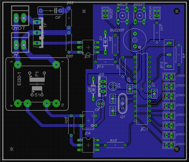
I have pcb that is schematically completed with the layout. Before i start the fabrication process i need some expert advise if the components placed and the wires routed are ok for the ac mains and the others. The load here will be a transformer. The ac mains are 240VAC and all works well as designed in the schematic on a bread broad except for the load for which MOC3023 is yet to arrive from where i've ordered.


Thanks in advance.


image


image

  • Sign in to reply
  • Cancel

Top Replies

  • rachaelp
    rachaelp over 9 years ago in reply to anishkgt +2
    Hi George, It looks like you're really learning a lot with this design and you've had lots of good advice from people on this thread already and the difference between the initial version you posted and…
  • michaelkellett
    michaelkellett over 9 years ago in reply to rachaelp +1 suggested
    For mains input spike suppression I think you are much better off with this kind of device: http://uk.farnell.com/epcos/b72214s0231k101/varistor-60-0j-230vac/dp/1004389 Farnell 1004389 This one is rated…
  • autodeskguest
    autodeskguest over 9 years ago in reply to anishkgt +1 suggested
    On 11/09/16 12:02, George Thomas wrote: Why two thrustirs to control the load and am trouble witching on yhe Triac. Triacs can suffer commutation problems with certain types of load - highly inductive…
Parents
  • anishkgt
    0 anishkgt over 9 years ago

    So i've re-arranged the Transformer and brought it back to the original and a rearranged the other components as well. To add a fuse i was thinking of a fuse rated at 2A, i was thinking replacing the fuse with a Thermistor. What would be the best rate to go with ? are thermistors chosen by current and temp or voltage or all the three ?

    image

    • Cancel
    • Vote Up 0 Vote Down
    • Sign in to reply
    • Verify Answer
    • Cancel
  • rachaelp
    0 rachaelp over 9 years ago in reply to anishkgt

    Hi George,


    Your clearances are all worse again. We're going round and round here a little now. Take a step back and read through all the suggestions again. Your current locations of C6, R20 and R22 are still not how were suggested and you are having to route a very oddly angled trace underneath C6 just because you have everything all knotted up. You need to take everything on board as a whole not just select different pieces for each iteration otherwise you'll never get this finished.


    Best Regards,


    Rachael

    • Cancel
    • Vote Up 0 Vote Down
    • Sign in to reply
    • Verify Answer
    • Cancel
  • anishkgt
    0 anishkgt over 9 years ago in reply to rachaelp

    so which one of those was correct or at least closer to it. will get it back to that and look how it goes from there. So about hassle was totally steps ahead to perfecting it.

    • Cancel
    • Vote Up 0 Vote Down
    • Sign in to reply
    • Verify Answer
    • Cancel
  • rachaelp
    0 rachaelp over 9 years ago in reply to anishkgt

    Start from the version in this post: https://www.element14.com/community/message/205178/l/re-ac-mains-on-a-pcb#205178

    • Cancel
    • Vote Up 0 Vote Down
    • Sign in to reply
    • Verify Answer
    • Cancel
Reply
  • rachaelp
    0 rachaelp over 9 years ago in reply to anishkgt

    Start from the version in this post: https://www.element14.com/community/message/205178/l/re-ac-mains-on-a-pcb#205178

    • Cancel
    • Vote Up 0 Vote Down
    • Sign in to reply
    • Verify Answer
    • Cancel
Children
  • autodeskguest
    0 autodeskguest over 9 years ago in reply to rachaelp

    Yup got it to there. How about this ? i've attached the eagle files as well.


    --

    To view any images and attachments in this post, visit:

    https://www.element14.com/community/message/205336


    • Cancel
    • Vote Up 0 Vote Down
    • Sign in to reply
    • Verify Answer
    • Cancel
  • autodeskguest
    0 autodeskguest over 9 years ago in reply to rachaelp

    Yup got it to there. How about this ? i've attached the eagle files as well.


    --

    To view any images and attachments in this post, visit:

    https://www.element14.com/community/message/205338


    • Cancel
    • Vote Up 0 Vote Down
    • Sign in to reply
    • Verify Answer
    • Cancel
  • anishkgt
    0 anishkgt over 9 years ago in reply to rachaelp

    Yup got it to there. How about this ? i've attached the eagle files as well.


    image

    Attachments:
    Spot Welder Controller ZC.zip
    • Cancel
    • Vote Up 0 Vote Down
    • Sign in to reply
    • Verify Answer
    • Cancel
  • rachaelp
    0 rachaelp over 9 years ago in reply to anishkgt

    I'll take a look at your Eagle files in the morning. That's getting closer, look to move R22, C6 and T1 to the right (don't rotate or in any other way rearrange them) to make space so the trace to pin 1 of the transformer keeps several mm of clearance from the other pad of the connector. Your connector pitch is too small still I believe so you won't be getting adequate clearance between your mains input traces anyway but you are eroding the clearance to almost nothing with the diagonal trace to the transformer.

    • Cancel
    • Vote Up 0 Vote Down
    • Sign in to reply
    • Verify Answer
    • Cancel
  • autodeskguest
    0 autodeskguest over 9 years ago in reply to rachaelp

    Am 07.09.2016 um 23:21 schrieb rachaelp:

    Start from the version in this post: https://www.element14.com/community/message/205178/l/re-ac-mains-on-a-pcb#205178 (/message/205178/l/re-ac-mains-on-a-pcb#205178)


    --

    To view any images and attachments in this post, visit:

    https://www.element14.com/community/message/205346


    Here is my answer to my earlier suggestions.

    I can not load up things to element14 because I'm not registered (and

    don't want to).

    So here is the board only because of the  upload limits at cadsoft.

    Maybe someone Rachael? can check it against the schematics and load the

    whole thing up to E14.

    BTW the polygon on board has "no name" and is a suggestion only like

    everything else image


    The whole thread could have been finished long ago if you had send the

    files earlier.

    Remember "A picture tells more than 1000 words"..... or so image


    --

    Mit freundlichen Grüßen / With best regards


    Joern Paschedag


    Attachments:
    Spot Welder JP.zip
    • Cancel
    • Vote Up 0 Vote Down
    • Sign in to reply
    • Verify Answer
    • Cancel
  • michaelkellett
    0 michaelkellett over 9 years ago in reply to anishkgt

    George, are you using the autorouter - if so turn it off and route the tracks sensibly by hand/brain - then when you get to something like the snail trail round D1 you'll notice that rotating D1 by 180 degrees will improve the routability  and allow you not to run a track past the inner edge of a pad on IC5.


    Unless you can afford >£10k for an autorouter they just are not worth using.


    MK

    • Cancel
    • Vote Up 0 Vote Down
    • Sign in to reply
    • Verify Answer
    • Cancel
  • rachaelp
    0 rachaelp over 9 years ago in reply to michaelkellett

    Michael Kellett wrote:


    George, are you using the autorouter - if so turn it off and route the tracks sensibly by hand/brain - then when you get to something like the snail trail round D1 you'll notice that rotating D1 by 180 degrees will improve the routability and allow you not to run a track past the inner edge of a pad on IC5.


    Unless you can afford >£10k for an autorouter they just are not worth using.


    MK

    I agree with your sentiments that this would be better hand routed than relying on the auto router. As an assistance tool the autorouter can help with some mundane tasks sometimes with careful setup and knowing what you are doing but in general I don't personally like using it.


    That said, I have looked at the files uploaded and whilst the input AC routing issue is relatively trivial to fix, the main reason the auto router is generally making such a HUGE mess is that the placement is not ready for routing yet, there is a lot of additional placement work to do before I would even consider putting any routing in. I also found some circuit peculiarities, e.g. why was the whole 5V rail supplied through a 1K resistor? I presume this was a mistake and that 1K was there for the power LED? Where are the bypass decoupling caps etc? Also, the pinout of the MEGA8 just leads to a total mess.


    I've spent a short while correcting errors and re-pinning parts of that and the autorouter will now route out all the LED's "nicely" (not really, it's still not tidy) without going round the houses. Also, looking at where all the +5V connections are.... well this is a net which we needs to get lots of places and these are scattered around the board.


    Finally, another reason for the very messy autorouter was the placements were not properly on grid which when you are using an autorouter that will lead to things being yukkier.


    Best Regards,


    Rachael

    • Cancel
    • Vote Up 0 Vote Down
    • Sign in to reply
    • Verify Answer
    • Cancel
  • rachaelp
    0 rachaelp over 9 years ago in reply to anishkgt

    Hi George,


    See my earlier post with some initial findings. I've been playing with your layout including re-pinning your microcontroller as it looked like that should be fine and you can just change the pin setup in the software as the functionality all seems fairly simple. Here is an image of how the layout works after I have altered everything. I could just upload the design files back but then I think maybe you should be trying this some more yourself as a learning exercise so you can work out what you need to do to achieve this for yourself image


    So this isn't perfect as I was just having a quick play around with it, if I were doing this for a real project of my own then there is probably quite a lot more I would change still, but within the confines of your existing circuit with some minor tweaks this is my first stab at a layout. You can see I have got the +5V and GND connected with polygons and all the other nets are routed much more cleanly as I tidied everything up in the placement first. There is much better isolation and clearances to the mains conductors are improved. I see your connectors are a little wider pitch than I had initially thought but personally I would probably swap those out for ones with a wider pitch still and I would add surge protection and EMI filtering.


    image


    Best Regards,


    Rachael


    UPDATE: Moved triac slightly to reduce high current trace lengths.

    • Cancel
    • Vote Up 0 Vote Down
    • Sign in to reply
    • Reject Answer
    • Cancel
  • anishkgt
    0 anishkgt over 9 years ago in reply to rachaelp

    Hey rachaelp


    Can't thank you enough for what you have done on the layout and yes i will definitely gonna try and learn to place things better and as suggested by all here i'l go with manual trace than auto routing. I did try doing it but got a little stuck here and there.


    So about the layout the AC and load connectors, aren't they not placed well, i mean when putting an actual connector would not fit a physical wire. The load connector would obstruct the AC connector when wiring. have you changed the pins i could read you have but did not notice in the schematic?

    • Cancel
    • Vote Up 0 Vote Down
    • Sign in to reply
    • Verify Answer
    • Cancel
  • anishkgt
    0 anishkgt over 9 years ago in reply to rachaelp

    was preparing a list components to buy and could not find 100nf ceramic cap here. So are anything more that i should consider buying for the optocoupler to drive the TRIAC.

    • Cancel
    • Vote Up 0 Vote Down
    • Sign in to reply
    • Verify Answer
    • Cancel
element14 Community

element14 is the first online community specifically for engineers. Connect with your peers and get expert answers to your questions.

  • Members
  • Learn
  • Technologies
  • Challenges & Projects
  • Products
  • Store
  • About Us
  • Feedback & Support
  • FAQs
  • Terms of Use
  • Privacy Policy
  • Legal and Copyright Notices
  • Sitemap
  • Cookies

An Avnet Company © 2026 Premier Farnell Limited. All Rights Reserved.

Premier Farnell Ltd, registered in England and Wales (no 00876412), registered office: Farnell House, Forge Lane, Leeds LS12 2NE.

ICP 备案号 10220084.

Follow element14

  • X
  • Facebook
  • linkedin
  • YouTube