element14 Community
element14 Community
    Register Log In
  • Site
  • Search
  • Log In Register
  • Community Hub
    Community Hub
    • What's New on element14
    • Feedback and Support
    • Benefits of Membership
    • Personal Blogs
    • Members Area
    • Achievement Levels
  • Learn
    Learn
    • Ask an Expert
    • eBooks
    • element14 presents
    • Learning Center
    • Tech Spotlight
    • STEM Academy
    • Webinars, Training and Events
    • Learning Groups
  • Technologies
    Technologies
    • 3D Printing
    • FPGA
    • Industrial Automation
    • Internet of Things
    • Power & Energy
    • Sensors
    • Technology Groups
  • Challenges & Projects
    Challenges & Projects
    • Design Challenges
    • element14 presents Projects
    • Project14
    • Arduino Projects
    • Raspberry Pi Projects
    • Project Groups
  • Products & Partners
    Products & Partners
    • Arduino
    • Avnet & Tria Boards Community
    • Dev Tools
    • Manufacturers
    • Multicomp Pro
    • Product Groups
    • Raspberry Pi
    • RoadTests & Reviews
  • About Us
    About the element14 Community
  • Store
    Store
    • Visit Your Store
    • Choose another store...
      • Europe
      •  Austria (German)
      •  Belgium (Dutch, French)
      •  Bulgaria (Bulgarian)
      •  Czech Republic (Czech)
      •  Denmark (Danish)
      •  Estonia (Estonian)
      •  Finland (Finnish)
      •  France (French)
      •  Germany (German)
      •  Hungary (Hungarian)
      •  Ireland
      •  Israel
      •  Italy (Italian)
      •  Latvia (Latvian)
      •  
      •  Lithuania (Lithuanian)
      •  Netherlands (Dutch)
      •  Norway (Norwegian)
      •  Poland (Polish)
      •  Portugal (Portuguese)
      •  Romania (Romanian)
      •  Russia (Russian)
      •  Slovakia (Slovak)
      •  Slovenia (Slovenian)
      •  Spain (Spanish)
      •  Sweden (Swedish)
      •  Switzerland(German, French)
      •  Turkey (Turkish)
      •  United Kingdom
      • Asia Pacific
      •  Australia
      •  China
      •  Hong Kong
      •  India
      •  Japan
      •  Korea (Korean)
      •  Malaysia
      •  New Zealand
      •  Philippines
      •  Singapore
      •  Taiwan
      •  Thailand (Thai)
      •  Vietnam
      • Americas
      •  Brazil (Portuguese)
      •  Canada
      •  Mexico (Spanish)
      •  United States
      Can't find the country/region you're looking for? Visit our export site or find a local distributor.
  • Translate
  • Profile
  • Settings
Autodesk EAGLE
  • Products & Partners
  • More
Autodesk EAGLE
EAGLE User Support (English) AC mains on a PCB ?
  • Blog
  • Forum
  • Documents
  • Events
  • Polls
  • Files
  • Members
  • Mentions
  • Sub-Groups
  • Tags
  • More
  • Cancel
  • New
Join Autodesk EAGLE to participate - click to join for free!
Actions
  • Share
  • More
  • Cancel
Forum Thread Details
  • State Verified Answer
  • Replies 107 replies
  • Answers 10 answers
  • Subscribers 193 subscribers
  • Views 21305 views
  • Users 0 members are here
Related

AC mains on a PCB ?

anishkgt
anishkgt over 10 years ago

A total newbie to eagle design and PCB fab. So plase bear with on my silly questions, trying to learn.


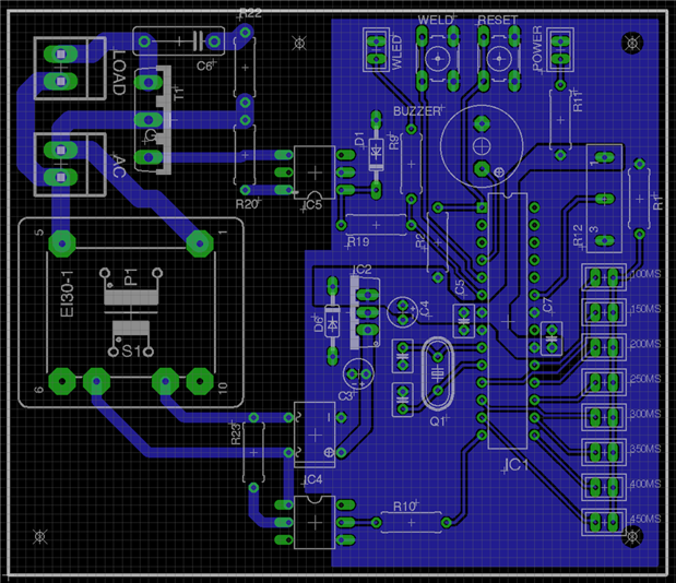
I have pcb that is schematically completed with the layout. Before i start the fabrication process i need some expert advise if the components placed and the wires routed are ok for the ac mains and the others. The load here will be a transformer. The ac mains are 240VAC and all works well as designed in the schematic on a bread broad except for the load for which MOC3023 is yet to arrive from where i've ordered.


Thanks in advance.


image


image

  • Sign in to reply
  • Cancel
  • rachaelp
    0 rachaelp over 10 years ago in reply to anishkgt

    George Thomas wrote:


    My idea for the connector was this.

    Yes that connector looks fine to me.


    George Thomas wrote:


    Not very experienced with selecting the TVS, actually heard oh them but haven't used them. Are these placed at the primary or the secondary winding of the transformer or after the 7805 ?

    The TVS goes on the primary side. It needs to be bidirectional and rated for greater than the peak voltage of the AC input so in the case of 240V mains it needs to be somewhere around 375V. In the link I provided the different types indicate what there intended usage is, there are several that say AC line.


    Best Regards,


    Rachael

    • Cancel
    • Vote Up 0 Vote Down
    • Sign in to reply
    • Verify Answer
    • Cancel
  • anishkgt
    0 anishkgt over 10 years ago in reply to rachaelp

    My idea for the connector was this. I haven't decided on the enclosure yet. Not very experienced with selecting the TVS, actually heard oh them but haven't used them. Are these placed at the primary or the secondary winding of the transformer or after the 7805 ?

    • Cancel
    • Vote Up 0 Vote Down
    • Sign in to reply
    • Verify Answer
    • Cancel
  • rachaelp
    0 rachaelp over 10 years ago in reply to anishkgt

    George Thomas wrote:


    Thanks rachaelp for the suggested layout. I think i would go with the first one. i had to catch a plane earlier hence short replies and delay.

    I actually think the latest one works better in some ways and it does give more options on connector type as it can cope with horizontal entry. You could even go for screw terminal type connectors right on the board so there weren't any removable connector plugs which for this, which I assume will be mounted inside a chassis, I think would be preferable.

    George Thomas wrote:


    So i read someone mentioning about EMI filters, how necessary would these be for my design ? limited space on the board so trying to keep the overall components less.

    Again assuming you have this in a chassis then you could have a filtered mains inlet IEC connector.


    More important than EMI filtering though is circuit protection from surges. I'd at the very least put a bi-directional TVS with a suitable standoff voltage across the AC input. Then if there is a surge on the line (surges can be many kVolts) this will clamp the voltage at a the specified clamp voltage and absorb energy until your inline fuse (in your inlet IEC connector or mains plug) blows from the increased current (which it will increase sharply once the TVS clamps).


    Take a look here for a range of possible devices: http://www.littelfuse.com/products/tvs-diodes/leaded.aspx


    Best Regards,


    Rachael

    • Cancel
    • Vote Up 0 Vote Down
    • Sign in to reply
    • Verify Answer
    • Cancel
  • anishkgt
    0 anishkgt over 10 years ago

    Thanks rachaelp for the suggested layout. I think i would go with the first one. i had to catch a plane earlier hence short replies and delay.


    Thanks guys for pointing out about R11, i've corrected it now.

    So as suggested by Rachel and the other have these in my cart now. What more would i need, i mean i have all working but the decouplers were something new.

    Ceramic Disc & Plate Capacitor, CC Series, 0.1 µF, ± 10%, Y5P, 50 V, Radial Leaded http://www.newark.com/on-semiconductor/1n5908g/tvs-diode-5w-5v-unidirectional/dp/42K2954

    TVS Diode, MOSORB Series, Unidirectional, 5 V, 8.5 V, Axial Leaded, 2 Pins http://www.newark.com/nxp/bt139-600-127/triac-sensitive-gate-16a-to-220ab/dp/70R3252

    Triac, 600 V, 70 mA, 5 W, 1.5 V, TO-220AB, 155 A

    COVER, PCB FUSE HOLDER, HTC
    FUSE HOLDER, 5X20MM, HTC, PCB


    So i read someone mentioning about EMI filters, how necessary would these be for my design ? limited space on the board so trying to keep the overall components less.

    • Cancel
    • Vote Up 0 Vote Down
    • Sign in to reply
    • Verify Answer
    • Cancel
  • rachaelp
    0 rachaelp over 10 years ago in reply to rachaelp

    Hi George,


    Here is another update which addresses your concerns about the connector orientation:

    image


    Best Regards,


    Rachael

    • Cancel
    • Vote Up 0 Vote Down
    • Sign in to reply
    • Verify Answer
    • Cancel
  • rachaelp
    0 rachaelp over 10 years ago in reply to rachaelp

    rachaelp wrote:


    I don't actually know what connectors these are specifically so haven't looked at the specs

    I've now looked at what you have planned on using and I think you really should change these to something else. Whilst they are actually rated for up to 600V and up to 12.5A, I really don't like that they are IDC connectors and your cable will have to be quite skinny to work with these.


    I'd look at something like these on the board: http://katalog.we-online.com/en/em/TBL_5_08_311_CLOSE_VERTICAL_PCB_HEADER_6913115001XX/691311500102?sid=9d4c2f552f

    For the cables maybe these as the mating half: http://katalog.we-online.com/en/em/TBL_5_08_352_HORIZONTAL_W_HOOK_ON_WIRE_SIDE_6913525100XX


    Best Regards,


    Rachael

    • Cancel
    • Vote Up 0 Vote Down
    • Sign in to reply
    • Verify Answer
    • Cancel
  • rachaelp
    0 rachaelp over 10 years ago in reply to anishkgt

    George Thomas wrote:


    was preparing a list components to buy and could not find 100nf ceramic cap here.

    100nF = 0.1uF so this would fit : http://www.newark.com/multicomp/mccc50v104ky5p/ceramic-capacitor-0-1uf-50v-y5p/dp/97M4053

    • Cancel
    • Vote Up 0 Vote Down
    • Sign in to reply
    • Verify Answer
    • Cancel
  • rachaelp
    0 rachaelp over 10 years ago in reply to anishkgt

    George Thomas wrote:


    Hey rachaelp


    Can't thank you enough for what you have done on the layout.

    You're welcome image


    George Thomas wrote:


    So about the layout the AC and load connectors, aren't they not placed well, i mean when putting an actual connector would not fit a physical wire. The load connector would obstruct the AC connector when wiring.

    I don't actually know what connectors these are specifically so haven't looked at the specs but I assumed that the mating half would fit within the bounding placement box of the connector on the board and that the wires would be coming out vertically. If this is not the case then a little more space is needed so you can get the mating connectors / wires in, but this should be achievable without too much additional change.


    Best Regards,


    Rachael

    • Cancel
    • Vote Up 0 Vote Down
    • Sign in to reply
    • Verify Answer
    • Cancel
  • anishkgt
    0 anishkgt over 10 years ago in reply to rachaelp

    was preparing a list components to buy and could not find 100nf ceramic cap here. So are anything more that i should consider buying for the optocoupler to drive the TRIAC.

    • Cancel
    • Vote Up 0 Vote Down
    • Sign in to reply
    • Verify Answer
    • Cancel
  • anishkgt
    0 anishkgt over 10 years ago in reply to rachaelp

    Hey rachaelp


    Can't thank you enough for what you have done on the layout and yes i will definitely gonna try and learn to place things better and as suggested by all here i'l go with manual trace than auto routing. I did try doing it but got a little stuck here and there.


    So about the layout the AC and load connectors, aren't they not placed well, i mean when putting an actual connector would not fit a physical wire. The load connector would obstruct the AC connector when wiring. have you changed the pins i could read you have but did not notice in the schematic?

    • Cancel
    • Vote Up 0 Vote Down
    • Sign in to reply
    • Verify Answer
    • Cancel
<>
element14 Community

element14 is the first online community specifically for engineers. Connect with your peers and get expert answers to your questions.

  • Members
  • Learn
  • Technologies
  • Challenges & Projects
  • Products
  • Store
  • About Us
  • Feedback & Support
  • FAQs
  • Terms of Use
  • Privacy Policy
  • Legal and Copyright Notices
  • Sitemap
  • Cookies

An Avnet Company © 2026 Premier Farnell Limited. All Rights Reserved.

Premier Farnell Ltd, registered in England and Wales (no 00876412), registered office: Farnell House, Forge Lane, Leeds LS12 2NE.

Follow element14

  • X
  • Facebook
  • linkedin
  • YouTube