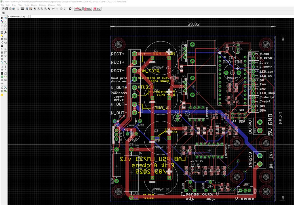
I need to get a bottom trace between two via's that currently are connected with an airwire.
However, when doing the trace at the bottom, the polygon does not cede to make way for that trace.
Using Eagle v7.6.0
How to solve?

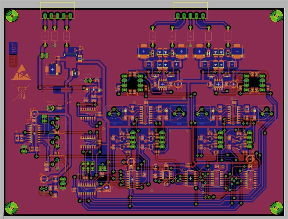
I need to get a bottom trace between two via's that currently are connected with an airwire.
However, when doing the trace at the bottom, the polygon does not cede to make way for that trace.
Using Eagle v7.6.0
How to solve?