element14 Community
element14 Community
    Register Log In
  • Site
  • Search
  • Log In Register
  • Community Hub
    Community Hub
    • What's New on element14
    • Feedback and Support
    • Benefits of Membership
    • Personal Blogs
    • Members Area
    • Achievement Levels
  • Learn
    Learn
    • Ask an Expert
    • eBooks
    • element14 presents
    • Learning Center
    • Tech Spotlight
    • STEM Academy
    • Webinars, Training and Events
    • Learning Groups
  • Technologies
    Technologies
    • 3D Printing
    • FPGA
    • Industrial Automation
    • Internet of Things
    • Power & Energy
    • Sensors
    • Technology Groups
  • Challenges & Projects
    Challenges & Projects
    • Design Challenges
    • element14 presents Projects
    • Project14
    • Arduino Projects
    • Raspberry Pi Projects
    • Project Groups
  • Products
    Products
    • Arduino
    • Avnet & Tria Boards Community
    • Dev Tools
    • Manufacturers
    • Multicomp Pro
    • Product Groups
    • Raspberry Pi
    • RoadTests & Reviews
  • About Us
  • Store
    Store
    • Visit Your Store
    • Choose another store...
      • Europe
      •  Austria (German)
      •  Belgium (Dutch, French)
      •  Bulgaria (Bulgarian)
      •  Czech Republic (Czech)
      •  Denmark (Danish)
      •  Estonia (Estonian)
      •  Finland (Finnish)
      •  France (French)
      •  Germany (German)
      •  Hungary (Hungarian)
      •  Ireland
      •  Israel
      •  Italy (Italian)
      •  Latvia (Latvian)
      •  
      •  Lithuania (Lithuanian)
      •  Netherlands (Dutch)
      •  Norway (Norwegian)
      •  Poland (Polish)
      •  Portugal (Portuguese)
      •  Romania (Romanian)
      •  Russia (Russian)
      •  Slovakia (Slovak)
      •  Slovenia (Slovenian)
      •  Spain (Spanish)
      •  Sweden (Swedish)
      •  Switzerland(German, French)
      •  Turkey (Turkish)
      •  United Kingdom
      • Asia Pacific
      •  Australia
      •  China
      •  Hong Kong
      •  India
      • Japan
      •  Korea (Korean)
      •  Malaysia
      •  New Zealand
      •  Philippines
      •  Singapore
      •  Taiwan
      •  Thailand (Thai)
      • Vietnam
      • Americas
      •  Brazil (Portuguese)
      •  Canada
      •  Mexico (Spanish)
      •  United States
      Can't find the country/region you're looking for? Visit our export site or find a local distributor.
  • Translate
  • Profile
  • Settings
Autodesk EAGLE
  • Products
  • More
Autodesk EAGLE
EAGLE User Support (English) BC184L transistor component
  • Blog
  • Forum
  • Documents
  • Events
  • Polls
  • Files
  • Members
  • Mentions
  • Sub-Groups
  • Tags
  • More
  • Cancel
  • New
Join Autodesk EAGLE to participate - click to join for free!
Actions
  • Share
  • More
  • Cancel
Forum Thread Details
  • Replies 20 replies
  • Subscribers 180 subscribers
  • Views 3956 views
  • Users 0 members are here
Related

BC184L transistor component

Andy Betts
Andy Betts over 9 years ago

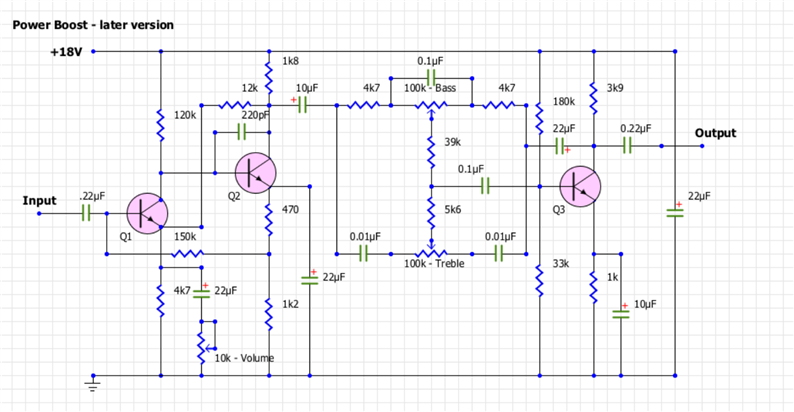
I'm taking my first baby steps into circuit design, with the intention of making guitar effect pedals that are as close to the original vintage spec as possible... Here's my issue.


I'm laying out the schematic for the circuit, and went to the library to pull out a BC184L transistor and there wasn't one. The closest to it I could find was a BC109, however I would really like the 184L as that's the correct one for the circuit. can I just create a new one in the library from an existing component that's virtually the same, or is there a resource for obtaining the correct library file, or am I missing something blatantly obvious as a newbie.


Thanks for your patience in advance...


Andy

  • Sign in to reply
  • Cancel

Top Replies

  • jc2048
    jc2048 over 9 years ago in reply to Andy Betts +1
    Overdrive? That's when the signal slams into BOTH rails, is it? Does that mean that the track title "Interstellar Overdrive" was a guitarist's joke? The values on your schematic look reasonably sensible…
  • Andy Betts
    Andy Betts over 9 years ago in reply to shabaz +1
    Thanks for your help guys... This is new territory to me, and don't want to spend too much time designing parts in Eagle, although I suspect that isn't going to happen. I'm currently copying and tweaking…
Parents
  • Andy Betts
    Andy Betts over 9 years ago

    Hi guys.


    Thank you all for your help, and comments. I've checked the schematic and that says that the 3 trannies in the circuit are BC169C, BC184C & BC109. However, I'm also working from an original photograph of the circuit and the trannies are ALL BC184L so I'll be going with that. The pin outs are the same on all those transistors I believe so i'll use the 109 from the library and rename it... Simples!! :-)


    For your interest, I'm recreating a Colorsound Power Boost version 2. The board will be the same, with board mounted pots, I just need to lay the circuit out in eagle and get the design as close to the trace as possible. I could manually trace the layout from the photo below, but it's a bit messy, and using Eagle to re-draw the circuit and create the board will ensure I don't make any ***-ups along the way as regards the circuit. I'm also sourcing (where practical) original components, so I've just received a delivery of NOS Mullard tropical fish caps the same as in the photo. all resistors are the same, I have however had to compromise with the axial electrolytic caps... I've gone with Vishay caps, a good brand and the same as what's used in the current power boost reissues.


    The photos below show a version 1 power boost, which had an extra 10k resistor which the version 2 didn't have. Apart from that they were identical.

    . imageimage


      imageimage

    • Cancel
    • Vote Up 0 Vote Down
    • Sign in to reply
    • Cancel
Reply
  • Andy Betts
    Andy Betts over 9 years ago

    Hi guys.


    Thank you all for your help, and comments. I've checked the schematic and that says that the 3 trannies in the circuit are BC169C, BC184C & BC109. However, I'm also working from an original photograph of the circuit and the trannies are ALL BC184L so I'll be going with that. The pin outs are the same on all those transistors I believe so i'll use the 109 from the library and rename it... Simples!! :-)


    For your interest, I'm recreating a Colorsound Power Boost version 2. The board will be the same, with board mounted pots, I just need to lay the circuit out in eagle and get the design as close to the trace as possible. I could manually trace the layout from the photo below, but it's a bit messy, and using Eagle to re-draw the circuit and create the board will ensure I don't make any ***-ups along the way as regards the circuit. I'm also sourcing (where practical) original components, so I've just received a delivery of NOS Mullard tropical fish caps the same as in the photo. all resistors are the same, I have however had to compromise with the axial electrolytic caps... I've gone with Vishay caps, a good brand and the same as what's used in the current power boost reissues.


    The photos below show a version 1 power boost, which had an extra 10k resistor which the version 2 didn't have. Apart from that they were identical.

    . imageimage


      imageimage

    • Cancel
    • Vote Up 0 Vote Down
    • Sign in to reply
    • Cancel
Children
  • autodeskguest
    autodeskguest over 9 years ago in reply to Andy Betts

    Andy Betts wrote:

    Thank you all for your help, and comments. I've checked the schematic

    and that says that the 3 trannies in the circuit are BC169C, BC184C &

    BC109. However, I'm also working from an original photograph of the

    circuit and the trannies are ALL BC184L so I'll be going with that.

    The pin outs are the same on all those transistors I believe so i'll

    use the 109 from the library and rename it... Simples!! image


    BC184C and L differ in pin mapping only. If you are creating a new

    layout anyway, I'd go with the version the makes for the easier

    routing.

    --

    Lorenz


    • Cancel
    • Vote Up 0 Vote Down
    • Sign in to reply
    • Cancel
  • jc2048
    jc2048 over 9 years ago in reply to Andy Betts

    Groovy! Boost that power, man!


    Made in London, too.


    What does it do to the sound? It looks like it's a just preamp and a tone control. Do the bass and treble cut as well, or is it just boost? Nice colour and love the graphics.

    [In the time I took to write this you've added the schematic and answered my question.]


    The BC184L has the base at one end, the BC109 in the middle. I vaguely seem to remember that there was a non-L version with a different pinout (it's the kind of thing that causes no end of confusion because it's inevitable that eventually somebody doing the buying will get offered a great deal on the wrong part).


    Also, the pins of the BC184 are in-line, whereas those of the BC109 were in a triangular shape. It was quite normal to bend the centre pin out to form the triangle shape when you had an in-line part. We were producing industrial equipment, so we used small plastic formers that the parts sat on and that guided and supported the legs, but this is the cheap and cheerful end of the market and you can see they've just stuffed the transistors in any old how.


    Do the BC184s have a letter at the end? Either BC184LB or BC184LC? The manufacturers grade transistors and offer them in a narrower range of gains than you'd get if you just had them from the end of the production line. If it has C parts, you probably want to match it - that was the higher gain bucket and they wouldn't have paid the extra if they didn't need them for the circuit operation.

    • Cancel
    • Vote Up 0 Vote Down
    • Sign in to reply
    • Cancel
  • Andy Betts
    Andy Betts over 9 years ago in reply to jc2048

    The guy that owns that particular power boost has told me that ALL the transistors are BC184L's.


    Also the axial caps are 22uf (The big ones), however the actual powerboost has different smaller axial caps than the schematic... the owner has listed the caps as follows:


    "the small blue caps are 6.4µF, the small green one is probably a 4.7µF and the large green one is a 22µF." However the schematic lists them as 220pf & 10uf......


    As regards the sound. it is a pre-amp, with a treble and bass boost... It's only when you get to about 3/4 on the volume knob does it start to break up into an overdrive. Used extensively by David Gilmour throughout the 70's with a fuzz box, he used the power boost and a big muff fuzz for the classic comfortably numb solo. he also used it on the Animals album and on the solos in Shine on.


    Any help with identifying caps and stuff would be greatly appreciated.


    here's more pics


    imageimage


    image

    • Cancel
    • Vote Up 0 Vote Down
    • Sign in to reply
    • Cancel
  • Andy Betts
    Andy Betts over 9 years ago in reply to Andy Betts

    Ok, so after a bit of digging I've found that Eagle has a package that is virtually identical to my BC184L that I want to use. However the pin outs are different so I thought probably the best thing to do would be to create my own library, and copy it into my library and edit it. I'll also learn more about using eagle at the same time :-)


    So the package I've copied over is a BC338, however it needs editing as I said because of the pin order. That is where I get lost, and I have a few questions:


    • How do I rename everything in that package from BC338 to BC184L?
    • there is a small window with "technologies" and "attributes" what is it, and how do I change it?


    Cheers in advance


    Andy

    • Cancel
    • Vote Up 0 Vote Down
    • Sign in to reply
    • Cancel
  • autodeskguest
    autodeskguest over 9 years ago in reply to Andy Betts

    Andy Betts wrote on Thu, 28 July 2016 13:20

    Ok, so after a bit of digging I've found that Eagle has a package that

    is virtually identical to my BC184L that I want to use. However the pin

    outs are different so I thought probably the best thing to do would be to

    create my own library, and copy it into my library and edit it. I'll also

    learn more about using eagle at the same time image


    Wow, you'll spare no expense to save a penny!


    If you had simply sat down and made the device when you first needed it,

    you'd have been done a long long time ago.  Then you would also:

    Have learned how to make symbols, packages, and devices in a library.

    You'll be surprised to find that this won't be the last time you can't find

    a device someone else has already made for you.


    Not have to vet something you "found on the internet somewhere".  Properly

    vetting a device can be more trouble than just making it the way you want

    in the first place.


    Have it adhere to whatever you standards and conventions are.  You can up

    front make sure the minimum silkscreen line width is adhered to, NAME and

    possibly VALUE appear in the silkscreen in the size text all your other

    parts use, the right data ends up the dDocu and related layers for the

    assembly drawing, etc.  Again, it's easier to just do these things right up

    front than to take something that might be right and check everything.


    --

    Web access to CadSoft support forums at www.eaglecentral.ca.  Where the CadSoft EAGLE community meets.


    • Cancel
    • Vote Up 0 Vote Down
    • Sign in to reply
    • Cancel
  • Andy Betts
    Andy Betts over 9 years ago in reply to autodeskguest

    Thanks for your words of wisdom... I've sorted it now. And to be honest it's probably quicker to copy an existing component and alter it, and rename it than it is to create my own.


    I've not built the project yet as I'm still waiting for components to arrive, I'm also having trouble tracking down some of the components for this build as they're now obsolete.


    I want to get the board etched in the next few days, hence why I want to get the schematic drawn and the board designed in Eagle

    • Cancel
    • Vote Up 0 Vote Down
    • Sign in to reply
    • Cancel
  • autodeskguest
    autodeskguest over 9 years ago in reply to Andy Betts

    Andy Betts wrote on Fri, 29 July 2016 03:50

    it's probably quicker to copy an existing component and alter it, and

    rename it than it is to create my own.


    Only as long as you keep dumpster-diving for library components instead of

    (gasp!) actually learning something.  A little work up front will save a

    lot of work and frustration in the future.  Once you do that, you'll also

    see how silly you've been.

    --

    Web access to CadSoft support forums at www.eaglecentral.ca.  Where the CadSoft EAGLE community meets.


    • Cancel
    • Vote Up 0 Vote Down
    • Sign in to reply
    • Cancel
  • Andy Betts
    Andy Betts over 9 years ago in reply to autodeskguest

    Do I detect an essence of sarcasm?? ;-)


    I'm qualified in using AutoCAD, have been using it for years... And I have to say that designing in Eagle is "clunky" to say the least and not at all intuitive. I will design my own devices if I have to.. but if there's something already there that just needs a tweak I'll do that. why try and reinvent the wheel when somebody has already done it. As a CAD program eagle is not a good program, and designing simple things takes thought... I'm used to using absolute coordinates.. Eagle doesn't appear to use that.

    • Cancel
    • Vote Up 0 Vote Down
    • Sign in to reply
    • Cancel
  • jc2048
    jc2048 over 9 years ago in reply to Andy Betts

    Overdrive? That's when the signal slams into BOTH rails, is it? Does that mean that the track title "Interstellar Overdrive" was a guitarist's joke?


    The values on your schematic look reasonably sensible to me. It's a high impedance input, so the small capacitor there is alright (in a hi-fi preamp, with a 10k input, you'd expect to see something more like 10uF or 22uF to get the response down to 20Hz). The low frequency roll-off at the input is from a filter formed by the cap and the input impedance - as the impedance goes up , the cap can come down in value for the same cut-off frequency. The 220p from the collector to the base of Q2 rolls off the high response (above 20kHz, so beyond hearing). It might be necessary for stability - to stop the preamp oscillating - or might be there to try and stop it receiving mediumwave radio stations. It looks like a very small value but it gets magnified by the transistor's gain. Couldn't say whether the tone control capacitors look right.


    The Mullard caps have the value as a 3-band (digit, digit, multiplier) colour code running down from the top. Here are photographs of 10nF, 100nF, and 220nF. You'll see the 220nF (red[2],red[2],yellow[4 zeroes]) has the two red bands running together and forming one fat band.


    image


    image


    image

    I seem to remember that the other bands are voltage and tolerance. Can't remember how they go, though.


    The 220pf capacitor is the brown disc between the potentiometer in the centre and one of the transistors. It's called a disc ceramic. Might just have 220 written on it, or something like that. They come with different dielectrics [the ceramic insulator that goes between the plates]. They have different properties, temperature stability etc, but I wouldn't have thought any of that matters to you for this.


    For the electrolytics, make sure that the working voltage is high enough. Designers vary in how much of an overhead they give themselves. It's probably good to have at least 1.5x, and 2x if you can. The one across the supply will need to be 25V or 35V. The others could be less, depending on what they are doing in the circuit.


    How are the potentiometers labelled? There are two main track types linear and logarithmic. [The log track is tapered.] Log types are often used as volume controls because of the way the response then is similar to how we hear different sound intensities. I should think the bass and treble controls are linear. The 'volume' might be either [because it's a guitar effect and not an amplifier as such]. Sorry to be a bit vague, here - I'm not an audio designer. Here are pictures of old log and lin pots to give you an idea.


    image


    image


    Sorry if you know all that and I'm lecturing you.

    • Cancel
    • Vote Up +1 Vote Down
    • Sign in to reply
    • Cancel
element14 Community

element14 is the first online community specifically for engineers. Connect with your peers and get expert answers to your questions.

  • Members
  • Learn
  • Technologies
  • Challenges & Projects
  • Products
  • Store
  • About Us
  • Feedback & Support
  • FAQs
  • Terms of Use
  • Privacy Policy
  • Legal and Copyright Notices
  • Sitemap
  • Cookies

An Avnet Company © 2025 Premier Farnell Limited. All Rights Reserved.

Premier Farnell Ltd, registered in England and Wales (no 00876412), registered office: Farnell House, Forge Lane, Leeds LS12 2NE.

ICP 备案号 10220084.

Follow element14

  • X
  • Facebook
  • linkedin
  • YouTube