element14 Community
element14 Community
    Register Log In
  • Site
  • Search
  • Log In Register
  • About Us
  • Community Hub
    Community Hub
    • What's New on element14
    • Feedback and Support
    • Benefits of Membership
    • Personal Blogs
    • Members Area
    • Achievement Levels
  • Learn
    Learn
    • Ask an Expert
    • eBooks
    • element14 presents
    • Learning Center
    • Tech Spotlight
    • STEM Academy
    • Webinars, Training and Events
    • Learning Groups
  • Technologies
    Technologies
    • 3D Printing
    • FPGA
    • Industrial Automation
    • Internet of Things
    • Power & Energy
    • Sensors
    • Technology Groups
  • Challenges & Projects
    Challenges & Projects
    • Design Challenges
    • element14 presents Projects
    • Project14
    • Arduino Projects
    • Raspberry Pi Projects
    • Project Groups
  • Products
    Products
    • Arduino
    • Avnet Boards Community
    • Dev Tools
    • Manufacturers
    • Multicomp Pro
    • Product Groups
    • Raspberry Pi
    • RoadTests & Reviews
  • Store
    Store
    • Visit Your Store
    • Choose another store...
      • Europe
      •  Austria (German)
      •  Belgium (Dutch, French)
      •  Bulgaria (Bulgarian)
      •  Czech Republic (Czech)
      •  Denmark (Danish)
      •  Estonia (Estonian)
      •  Finland (Finnish)
      •  France (French)
      •  Germany (German)
      •  Hungary (Hungarian)
      •  Ireland
      •  Israel
      •  Italy (Italian)
      •  Latvia (Latvian)
      •  
      •  Lithuania (Lithuanian)
      •  Netherlands (Dutch)
      •  Norway (Norwegian)
      •  Poland (Polish)
      •  Portugal (Portuguese)
      •  Romania (Romanian)
      •  Russia (Russian)
      •  Slovakia (Slovak)
      •  Slovenia (Slovenian)
      •  Spain (Spanish)
      •  Sweden (Swedish)
      •  Switzerland(German, French)
      •  Turkey (Turkish)
      •  United Kingdom
      • Asia Pacific
      •  Australia
      •  China
      •  Hong Kong
      •  India
      •  Korea (Korean)
      •  Malaysia
      •  New Zealand
      •  Philippines
      •  Singapore
      •  Taiwan
      •  Thailand (Thai)
      • Americas
      •  Brazil (Portuguese)
      •  Canada
      •  Mexico (Spanish)
      •  United States
      Can't find the country/region you're looking for? Visit our export site or find a local distributor.
  • Translate
  • Profile
  • Settings
3M
  • Products
  • Manufacturers
  • 3M
  • More
  • Cancel
3M
Forum Signal Tracer (Old school)
  • Blog
  • Forum
  • Documents
  • Events
  • Polls
  • Files
  • Members
  • Mentions
  • Sub-Groups
  • Tags
  • More
  • Cancel
  • New
Join 3M to participate - click to join for free!
Actions
  • Share
  • More
  • Cancel
Forum Thread Details
  • Replies 12 replies
  • Subscribers 10 subscribers
  • Views 9548 views
  • Users 0 members are here
  • idea
Related

Signal Tracer (Old school)

supper_slash
supper_slash over 9 years ago

One of my projects for this year is to create a "new age" signal tracer like I used when i was a kid.

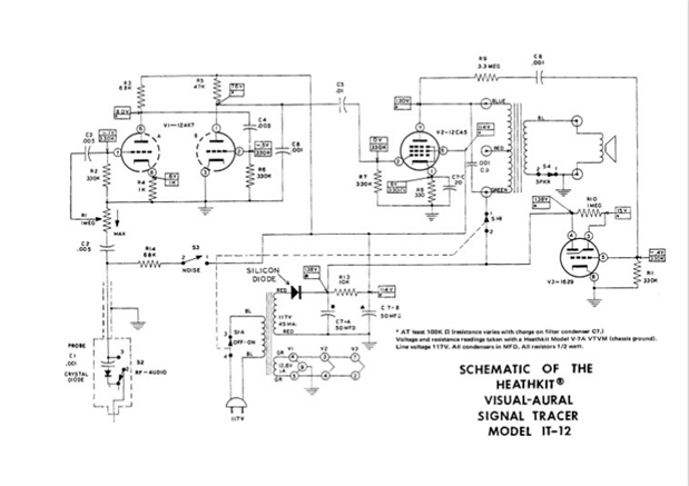
What I had was an old heathkit IT-12 pictured below.

image


The thing is i have no clue how this worked. I loved using it, and well just playing with it. It was sencitive efuff to hear audio runing through circuts without contacting the circuts, just getting the tip close to a trace.


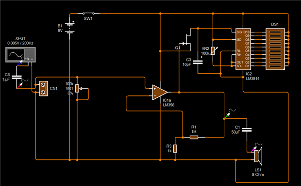
So to start things off I created a audio amplifyer circut that I think is how this unit worked.

image

There are 2 things that I am compleetly lost about though.


  1. How to make, or what to use for the probe.
  2. How to make the visual circut.

1~I was thinking of taking a nail, and wraping copper wire around the nail to create a pickup coil, but i have no idea if this would work or if there is something better to try.

I am open to any ideas.


2~I was thinking of a 10 segment led bargraph desplay. But where would I need to conect the driver up to in the circut in the diagram? Would it be the the + side of C5?

I ordered some LM358N LM358 358 Low Power Dual Op-Amp IC's for this project that should be here on the 10th.

So I am planning on bread boarding this after that.


Also, I was thinking about starting to documenting some of my projects by video maby. So this might be one of the first ones I may try to document.

I have been feeling inspired by @Peter Oakes.

  • Sign in to reply
  • Cancel

Top Replies

  • shabaz
    shabaz over 9 years ago +2
    Great topic! Funnily enough, this is something I've been working on just a couple of days ago : ) The circuit I went for (not yet complete, but initial tests are ok-ish, I want to improve it) uses just…
  • shabaz
    shabaz over 9 years ago in reply to jc2048 +2
    Hi Jon, Exactly as you say, it would be good to build that into a small screened handheld enclosure (the FET part, if not the entire circuit), with a cable down to the battery box/speaker/LM386. Basically…
  • jw0752
    jw0752 over 9 years ago +1
    Hi Lupe, This sounds like a good project if you do any audio equipment servicing. I used to use a cheap imitation of the HeathKit in the old days. In your final design you are going to want a higher impedance…
  • jw0752
    jw0752 over 9 years ago

    Hi Lupe,

         This sounds like a good project if you do any audio equipment servicing. I used to use a cheap imitation of the HeathKit in the old days. In your final design you are going to want a higher impedance input. The schematic you display has the resistance of the volume control as a load on your input. I think you will want a small capacitor in series with the input. If I was going to make a probe for one of these I think I would use a regular meter test probe and put a coax cable on it. At the probe I would expand the shielding over the handle of the probe and then cover it with heat shrink. This would keep interference down and give a good point with which to touch the circuit traces. With a capacitor in series you will not have to worry about touching a voltage rail. I have seen small bar displays that give a basic voltage level reading. You can drive the output of your amplifier into a voltage integrator and use the bar graph to read the voltage. You should be able to find some circuit suggestion if you google VU meter circuits. I look forward to seeing what you come up with.


         I use to see those indicator tubes, like the one on the Heath Kit, on some of the old radios that I used to play with. As the signal got stronger the green light of the display would close down. It was very cool.


    John

    • Cancel
    • Vote Up +1 Vote Down
    • Sign in to reply
    • Cancel
  • jw0752
    jw0752 over 9 years ago

    Hi Lupe,

    Here is a schematic of the original unit.


    image


    This is basically a high gain audio amplifier. The probe has a switch that drops a .001 uF cap and a diode into the circuit for the RF and bypasses the cap and diode for audio signals. There is still a cap C2 .005 uF in series with the input potentiometer. There is quite a bit of information on the web about this little tracer and they are selling on e-bay for over $100.00. Not bad considering they originally sold for $20.00.

    John

    • Cancel
    • Vote Up +1 Vote Down
    • Sign in to reply
    • Cancel
  • shabaz
    shabaz over 9 years ago

    Great topic! Funnily enough, this is something I've been working on just a couple of days ago : )

    The circuit I went for (not yet complete, but initial tests are ok-ish, I want to improve it) uses just a single FET, the output is sufficient to drive headphones (or could append an audio amp to it, like LM386).


    As jw0752 says, you need a high input impedance, also the '358 circuit doesn't necessarily need the push/pull stage, it could probably drive a 64-ohm speaker with reasonable level of volume (64-ohm speakers are available from Farnell/Newark) or

    headphones with a lot of loudness. The push/pull stage as shown will have a lot of distortion but that's not an issue for such a test tool as you probably envisage the use of it (my circuit intentionally has excessive distortion for other reasons, depending

    on experiments I still want to do).

    Or use a LM386 for more output. An old Radio Shack test amplifier used the LM386 from memory too. The bar graph idea is very cool.


    For a TO-92 type device the  2N38192N3819 is an extremely popular JFET there are some example amplifier circuits here, about half-way down the page - I've not tried these though.


    As John says, the shielding will be super important otherwise there is a lot of hum.


    For the probe, a very expensive (but nice) option is a Pomona case - they have one which is aluminium and a useful size for a probe. I can try to dig out a part number if you require it. However I probably will go for a sweets/candy enclosure,

    something like a very small tin of mints for the high impedance input amplifier, and a cable to the rest of it (speaker/battery).

    For the pointy tip, filed steel could be used, but (again) Pomona sell a nice probe accessories kit that contains about five sharp tips, so good enough for 5 projects. It needs shielding though. So the coax idea from John is very good.

    • Cancel
    • Vote Up +2 Vote Down
    • Sign in to reply
    • Cancel
  • DAB
    DAB over 9 years ago

    Yes, I have used similar gear, though I did not do much audio work.


    The device was mostly intended for people to track the audio level through each stage of a complex amplifier system.


    You had to be careful about adjusting the gain too high and introduce distortions at the desired frequency levels.


    DAB

    • Cancel
    • Vote Up 0 Vote Down
    • Sign in to reply
    • Cancel
  • supper_slash
    supper_slash over 9 years ago

    Taking in your suggestions, here is revision 2 of the circuit.

    image


    @John Wiltrout I was thinking the highlighted cap (C1) would provide the higher impedance needed. Am I thinking wrong?

    I love the idea of the probe, that will be the way to go.  Thank you for the  schematic, I am afraid I am not fluent with the tubes, however. image

    I am focusing on solid state, for now, I would like to move into the vacuum tubes later, I love the vintage tube amplifiers.


    @shabaz  


    I pulled the transistors off of the circuit, and plan to see if that can, in fact, drive a speaker/headphones. I have a feeling I will need something to drive them, so I am thinking of adding some fets like you mentioned in place of the PNP/NPN's.

    I like the input you have on this, do you have any posts or schematics of you circuits posted? or that you can share? Maby we can work together.?  image

    Just a thought.

    By the way, the led bar is added to the circuit.image

    • Cancel
    • Vote Up 0 Vote Down
    • Sign in to reply
    • Cancel
  • jw0752
    jw0752 over 9 years ago in reply to supper_slash

    Hi Lupe,

    When one talks about input impedance one is referring to the impedance looking into the input of the circuit. If I look into the input of your circuit I see the resistance of VR1. Look at the tube schematic and you will see if we look into the input we see the impedance of C2 at the least and if the RF switch is on we have the impedance of C1 and C2 in series. At least at low frequencies the capacitors have much higher impedance than the VR1. Don't worry too much about tube technology. I strongly suspect that it isn't coming back. I have been waiting with my tube manual in hand for 50 years. Good luck on your project.

    John

    • Cancel
    • Vote Up +1 Vote Down
    • Sign in to reply
    • Cancel
  • shabaz
    shabaz over 9 years ago in reply to supper_slash

    Hi Lupe,


    My circuit uses a surface-mount-only part, and isn't ready for prime-time, but as an alternative I drew up the circuit below - uses through-hole parts.

    It would be the high impedance input stage, so you could attach the right side of it to your LM358, or a LM386 circuit.

    Any popular N-ch JFET could be tried any of these are common  2N38192N3819 2N5486 J310

    It has a very high input impedance (of the order of Mohms). It will distort and clip perhaps above a few volts input, but that's ok

    (doesn't matter for your application). It will need a screened box.

    I have not built this circuit but it should function(played around with the  2N38192N3819 a lot in the past : )


    image


    For the speaker stage, I personally really like the LM386, it is a fine audio amp for such test applications, but if you want to use the LM358, then here is a known working circuit

    that I built up a while ago as a quick test amp for some circuit (it is not hi-fi). It uses the dual op amp version of the '358 (LM2904)  for stereo but you only need one channel of

    course so could be replaced with the '358 (the pin numbers will be different).

    You don't need the input capacitor drawn below since the JFET circuit above already has that.

    This circuit was tested with headphones (and it was loud), not a speaker, but it should be ok-ish with a 64-ohm speaker - that needs testing though!

    image

    • Cancel
    • Vote Up +1 Vote Down
    • Sign in to reply
    • Cancel
  • supper_slash
    supper_slash over 9 years ago in reply to shabaz

    Very good ideas. I have incorporated it and updated the schematic.

    image


    Hoping to have something on a breadboard, and prototype by the end of the month.

    Using a 358, I have on hand to see how it goes.

    I added C6, that will be in the probe, and I may need to add a diode, but if I do it will be switchable.

    • Cancel
    • Vote Up 0 Vote Down
    • Sign in to reply
    • Cancel
  • jc2048
    jc2048 over 9 years ago in reply to shabaz

    Are you going to have the FET right next to the probe tip?


    It seems to me, the original has two main difficiencies with regard to the input.


    Firsty, the large ratio between the circuit-to-probe-tip capacitance (a few pf) and the screened cable capacitance to ground (several hundred pf) means that the signal that the amplifier input sees is so low that it needs a lot of gain to get it back to a usable level. The original designer didn't have much choice - it would have been too difficult to put a valve at the probe tip - but you have the advantage that, with small surface-mount components, you could. By driving the screened cable with the FET, that capacitance is no longer a factor, and the signal reduction at the input becomes more modest - it will still be there, because of the capacitance from the probe back to the probe case, but should be much less. [If you wanted to be really clever, you might actively drive a shield behind the probe tip and reduce the capacitance even further, though that's probably going too far (and might not even work - I'm just throwing in a random idea there).]


    Secondly, the high-pass filter formed by the few pf at the input and the input impedance at the amplifier really rolls off the signal at low frequencies. You're already dealing with that by using the FET, but you might be able to push it up further if it's close in to the tip [where you want pick-up anyway because that's the whole point].

    • Cancel
    • Vote Up +1 Vote Down
    • Sign in to reply
    • Cancel
  • jc2048
    jc2048 over 9 years ago in reply to supper_slash

    I think you've simplified your circuit too much.


    The artificial ground (potential divider and cap) and the dc blocking capacitor on the gain resistors were necessary.


    The input potentiometer doesn't do anything very useful the way you've connected it.


    Are you using a simulator that tells you that the circuit you've drawn works ok?

    • Cancel
    • Vote Up 0 Vote Down
    • Sign in to reply
    • Cancel
>
element14 Community

element14 is the first online community specifically for engineers. Connect with your peers and get expert answers to your questions.

  • Members
  • Learn
  • Technologies
  • Challenges & Projects
  • Products
  • Store
  • About Us
  • Feedback & Support
  • FAQs
  • Terms of Use
  • Privacy Policy
  • Legal and Copyright Notices
  • Sitemap
  • Cookies

An Avnet Company © 2025 Premier Farnell Limited. All Rights Reserved.

Premier Farnell Ltd, registered in England and Wales (no 00876412), registered office: Farnell House, Forge Lane, Leeds LS12 2NE.

ICP 备案号 10220084.

Follow element14

  • X
  • Facebook
  • linkedin
  • YouTube