
Welcome to the Panasonic Industry page on element14. Here you can find things such as our latest news, training videos, and product details. Additionally, you can engage with us in our forums.
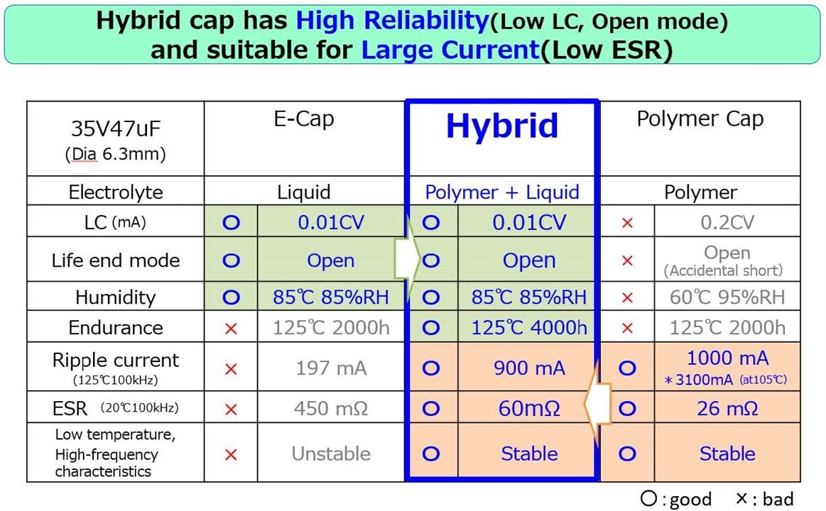
Panasonic’s hybrid capacitors are engineered to meet the rapidly intensifying demands of transportation electronics. By combining the strengths of electrolytic and polymer capacitor technologies, Panasonic delivers a balance of high ripple current, long operational life, and failsafe reliability—attributes essential in EVs, e‑bikes, AGVs, and automotive power electronics.
Hybrid capacitors have become one of the most impactful innovations in Panasonic’s passive component lineup, enabling compact, thermally robust, and electrically stable designs for high‑power mobility systems.
Designers working on EV inverters, DC‑link circuits, e‑bike motor drivers, and industrial AGVs face several recurring challenges:
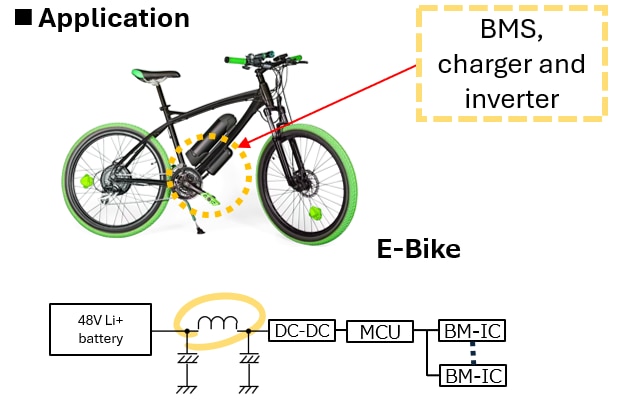
E‑bike and AGV platforms demand DC‑link capacitors capable of managing 20–60 A ripple currents—especially in systems ranging from 500 W to 6 kW.
Conventional aluminum electrolytic capacitors often require multiple parts in parallel, consuming valuable PCB area and increasing BOM cost.
Modern EVs and AGVs require product lifetimes of 10 years and operating endurance exceeding 4,000 hours at 125 °C, far surpassing the typical 2,000‑hour rating of general electrolytic capacitors.
This creates a significant reliability gap traditional technologies cannot bridge.
Polymer capacitors can offer low ESR and high current handling but risk short‑circuit failure, which is unacceptable in safety‑critical automotive and industrial systems.
Regulations require open‑circuit failsafe behavior to prevent secondary damage or thermal hazards.
Panasonic’s hybrid technology directly addresses all three challenges simultaneously.
Panasonic’s hybrid capacitors merge liquid electrolyte with conductive polymer to create a component category that excels in both performance and safety.
This allows engineers to reduce component count, shrink board size, and enhance system reliability—crucial benefits in compact traction inverters and motor‑control units.
Panasonic offers multiple hybrid capacitor families tailored for different mobility applications:
| Series | Capacitance | Ripple Current | Miniaturization |
|---|---|---|---|
| ZTU | Up to 1.7× larger than entry‑level hybrids (e.g., 330 µF → 560 µF, φ10×10.2 mm) | 1.8× improvement (2900 mA → 3500 mA) | Smaller case option: φ10×10.2 → φ8×10.2 |
| ZUU | Highest capacitance class, up to 1000 µF | Industry‑leading ripple current up to 6100 mA | Enables 1‑to‑many replacements to reduce cost/space |
| ZVU | 1.7× capacity increase compared to ZC series | Maintains high ripple current similar to ZV (up to 4.6 A in 10×10.2 mm) | Supports design consolidation & PCB reduction |
These series are widely used in EV power steering, cooling fans, OBCs, and e‑bike motor drives.
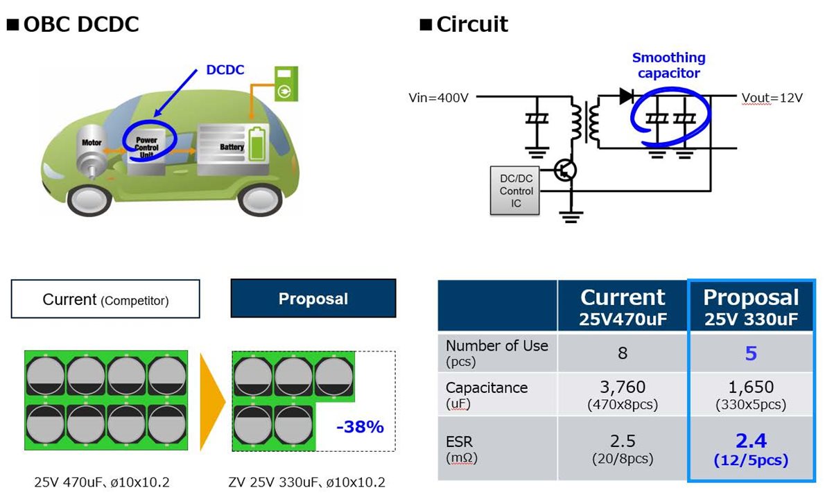
System Overview
48 V Li‑ion Battery → DC‑DC Converter → BM‑IC → Motor Drive Inverter
Conventional Design
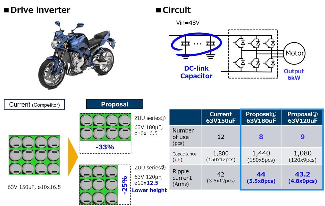
Conventional Design
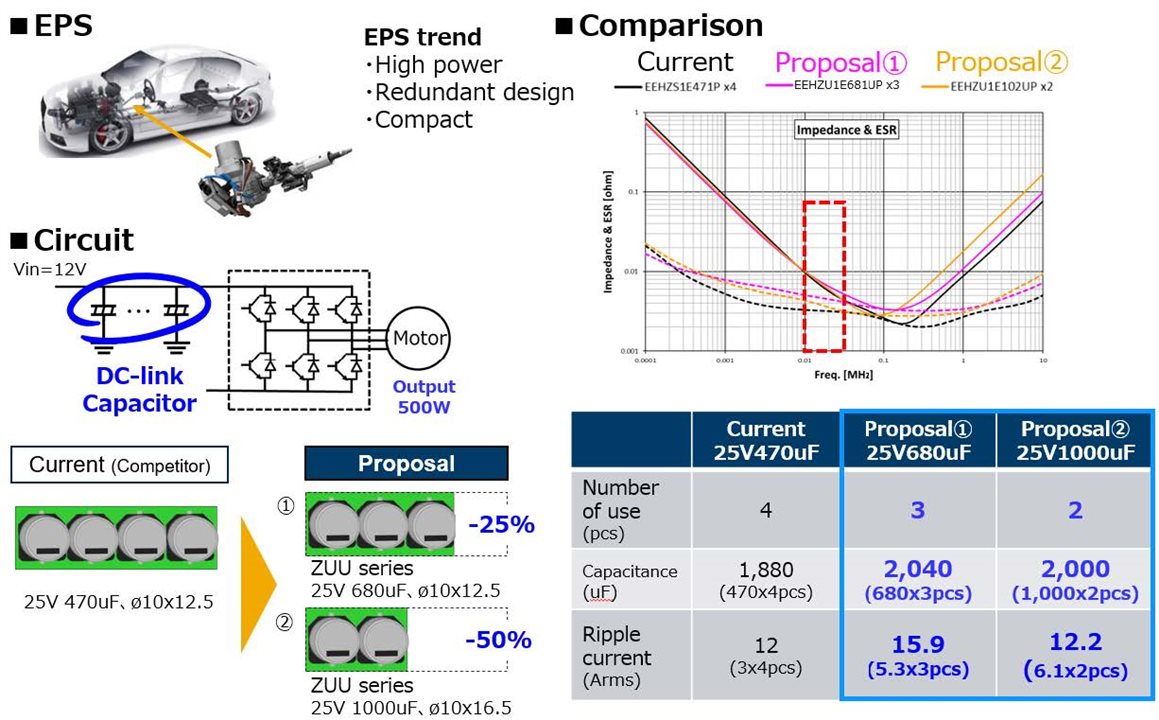
25 V, 1000 μF × 2 pcs (φ10 × 16.5 mm)
Total Capacitance: 2,000 μF (+6.4%)
Ripple Current: 12.2 Arms
Component count reduced by 50%
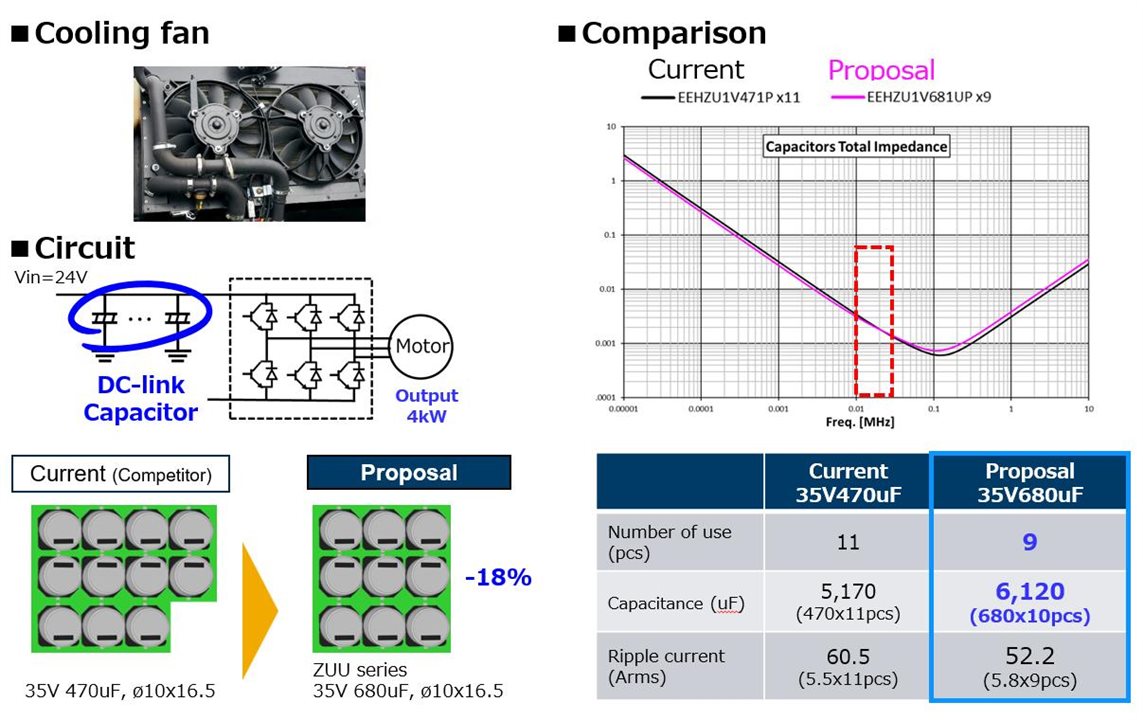
Conventional Design
35 V, 680 μF × 9 pcs
Total Capacitance: 6,120 μF (+18%)
Component reduction: –18%
Conventional Design
Power inductors are central to every high‑efficiency power conversion stage found in electric vehicles, e‑bikes, AGVs, battery management systems, and compact industrial drives. As system voltages rise and switching frequencies increase, passive magnetic components must deliver higher current, lower EMI, and greater thermal stability—all within increasingly compact mechanical footprints.
Panasonic’s proprietary Metal Composite (MC) Core inductors are engineered precisely for these next‑generation requirements. By combining advanced materials science with robust structural design, Panasonic creates inductors that offer exceptional current capability, low DC resistance, minimal magnetic flux leakage, and industry‑leading thermal performance, enabling designers to optimize power density without compromising reliability.
As mobility platforms move toward higher power and higher switching frequencies, traditional ferrite-core inductors encounter several limitations. Panasonic’s MC-core technology directly addresses these challenges.
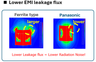
E‑bikes, AGVs, and compact EV systems employ fast-switching MOSFET/SiC power stages that generate high-frequency electromagnetic noise.
Ferrite inductors typically exhibit high leakage flux, making compliance with EMC regulations more difficult.
Panasonic MC inductors dramatically reduce radiated noise through a dense metal‑composite material structure that naturally suppresses flux leakage—greatly simplifying EMC countermeasures.
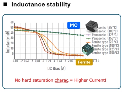
As system voltages grow to 48–60 V and beyond, inductors must handle 5 A+ continuous currents without requiring larger, bulkier components.
Ferrite cores saturate sharply, limiting their downsizing potential.
MC-core inductors allow engineers to reduce size while supporting higher currents, maintaining stable inductance even during transient loads.
In harsh automotive environments—near motors, inverters, or engine compartments—temperatures frequently exceed 100 °C.
Heat causes drift in inductance, impacts efficiency, and accelerates component aging.
Panasonic MC inductors deliver stable electrical performance from –55 °C to +170 °C, offering dependable reliability for automotive powertrains and outdoor AGVs.
Panasonic’s MC inductors integrate a metal‑composite magnetic core that offers a unique combination of high current handling, low EMI, and stable inductance, enabling superior power‑conversion performance compared to ferrite-based competitors.
A comparison of 22 μH inductors highlights how MC-core technology supports larger current ratings in significantly smaller form factors—ideal for space‑constrained BMS and drive-inverter boards.
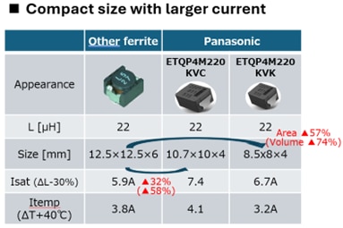
Conventional ferrite inductors experience abrupt inductance collapse under high current (hard saturation).
Panasonic MC inductors maintain stable inductance across the full operating range.
These attributes make Panasonic MC inductors ideal for EV powertrains, ADAS power modules, onboard chargers, and next‑generation mobility platforms.
Panasonic’s MC inductors deliver tangible design advantages in 48‑V Li‑ion battery ecosystems used across e‑bikes, AGVs, and compact mobility vehicles.
Significant Space Savings in BMS Boards
Simplified EMI Compliance
Thermal Robustness for Harsh Environments
High Saturation Current for Design Margin
Optimized for SMD Integration
High-Voltage, High-Current Capability
As mobility platforms continue their shift toward electrification and digitalization, resistors play an increasingly critical role in enabling safe, precise, and power‑efficient operation. From high‑voltage battery management in EVs to precision sensing in e‑bikes and rugged AGV control circuitry, the demands placed on surface‑mount resistors have intensified dramatically.
Panasonic’s resistor portfolio—including the ERJP, ERJB, ERJ*BW, ERA, and ERJU series—delivers unmatched performance across power density, precision, thermal stability, and environmental resistance.
These components are designed specifically for harsh and space‑constrained applications common in modern transportation systems, making them ideal for engineers building next‑generation mobility solutions.
Different sections of transportation electronics require resistors with highly specialized characteristics. Panasonic offers tailored resistor families that address each circuit’s unique demands.
Key Requirements:
Technical Challenge:
Accurate detection of small voltage fluctuations in EVs and BMS circuits is extremely sensitive to resistance drift, especially under harsh conditions from –40 °C to +125 °C.
Recommended Panasonic Solution:
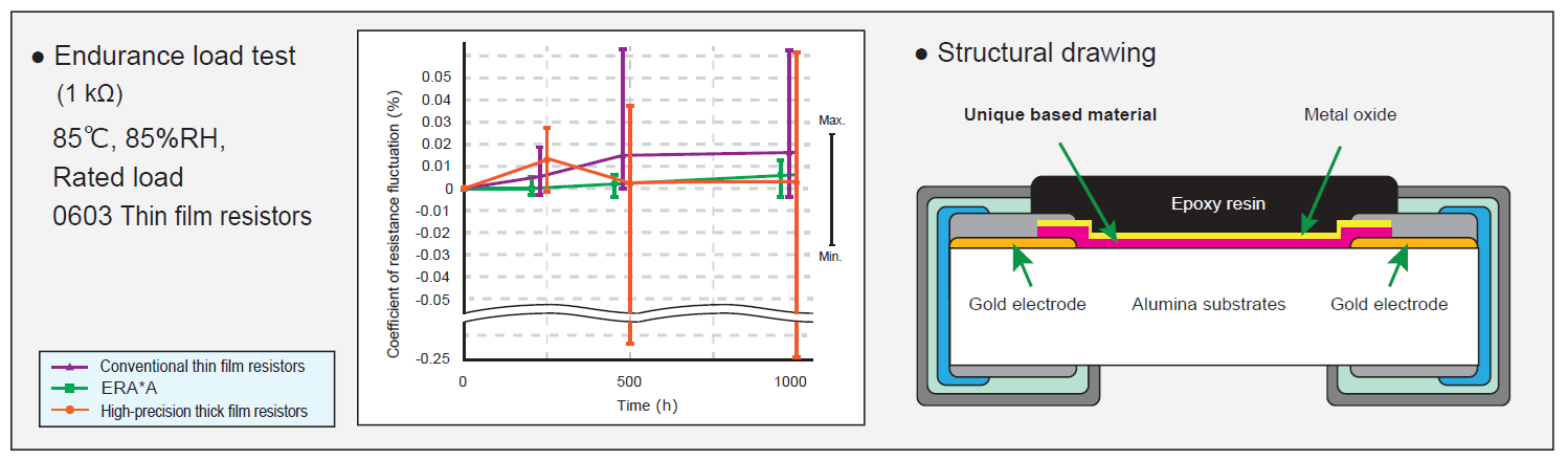
Achieves high reliability through proprietary resistive material (±0.1% tolerance after durability testing)-ERA-A series
Key Requirements:
Technical Challenge:
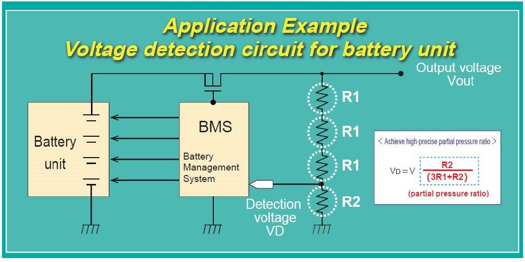
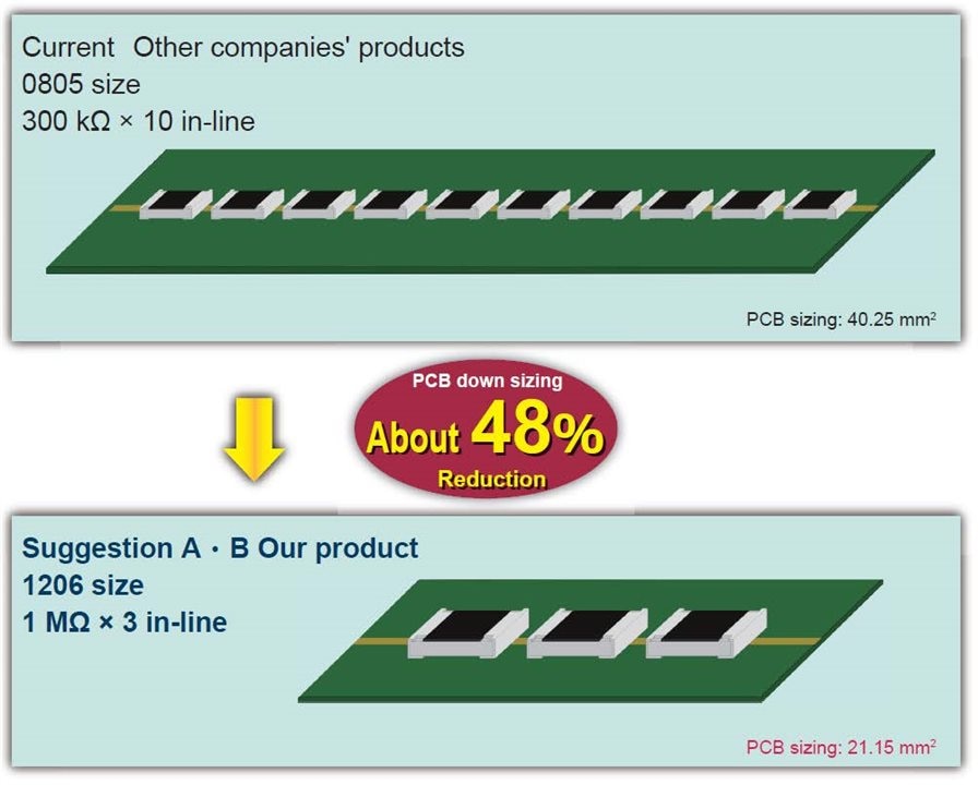
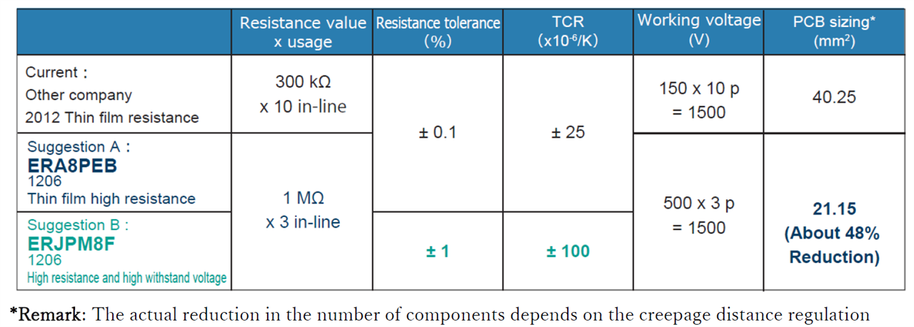
Traditional voltage dividers require multiple low‑voltage resistors in series, increasing PCB area, complicating layout, and impacting cost.
Recommended Panasonic Solutions:
*Remark: The actual reduction in the number of components depends on the creepage distance regulation
Key Requirements:
Technical Challenge:
Current sensing applications face resistive drift and thermal stress, especially in EV traction inverters.
Recommended Panasonic Solutions:
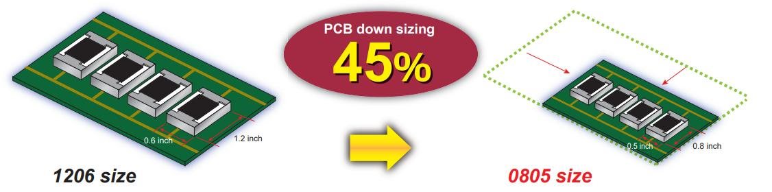
These devices improve power handling, reduce hotspot formation, and allow PCB downsizing.
Key Requirements:
Technical Challenge:
Fast‑switching IGBT and MOSFET drivers experience constant surges and thermal load, demanding robust resistor structures.
Recommended Panasonic Solutions:
Key Requirements:
Technical Challenge:
Agricultural AGVs, industrial vehicles, and railway systems frequently encounter sulfur‑rich environments that cause sulfuration failures in standard resistors.
Recommended Panasonic Solutions:
Technical Challenge:
BMS voltage accuracy can degrade due to resistance drift from temperature fluctuations and long‑term operation.
Panasonic Solution:
Image: image_c67DrOiSie00ZhSdaFzMxQ==(insert here)
Technical Challenge:
High‑voltage BMS circuits (300–500 V) traditionally require 10+ resistors in series, increasing PCB area and complicating creepage requirements.
Panasonic Solution:
Component Reduction Example:
Technical Challenge:
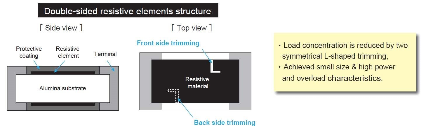
High currents generate heat and vibration stress that can cause drift and failure in standard resistors.
Panasonic Solutions:
ERJ*BW (Double‑Sided Resistive Element)
ERJB/D (Wide Terminal)
Technical Challenge:
Gate drivers in EV traction inverters require resistors with strong surge endurance and power dissipation.
Panasonic Solutions:
Technical Challenge:
Outdoor AGVs and agricultural vehicles often see sulfur‑rich gases that cause silver‑terminal sulfuration.
Panasonic Solution:
Panasonic offers a comprehensive lineup of passive components engineered to meet the stringent demands of transportation systems—ranging from high‑power e‑bike inverters to automotive BMS and harsh‑environment AGVs.
This section provides application‑specific recommendations to help design engineers quickly select the ideal Panasonic components and seamlessly transition into purchasing decisions on platforms such as element14, Mouser, Digi‑Key, and DesignSpark.
High‑power traction inverters in e‑bikes and AGVs require components that can withstand large ripple currents, deliver stable inductance, and provide accurate current sensing. Panasonic’s hybrid capacitors, metal‑composite inductors, and shunt resistors ensure safe, compact, and efficient inverter design.
DC‑Link Capacitors:
ZUU / ZVU / ZSU Series
Current‑Sensing Resistors:
ERJD Series
Power Inductors:
ETQP4M220KV* Series
High‑Precision Resistors:
ERA‑V / ERA‑K / ERA‑P Series
Battery Management Systems require high‑voltage precision resistors and long‑life capacitors capable of surviving elevated temperatures and high electrical stress. Panasonic’s products address these reliability and safety needs.
DC‑Link Capacitors:
ZUU / ZSU Series
High‑Voltage Resistors:
ERA8P / ERJPM8 Series
High‑Precision Resistors:
ERAA, ERA‑V / ERA‑K Series
Systems like Electric Power Steering, On‑Board Chargers, and inverters require components with high surge tolerance, long life, and stable performance at high temperatures.
DC‑Link Capacitors:
ZUU / ZV Series
Current‑Sensing Resistors:
ERJD / ERJ*BW Series
High‑Voltage Resistors:
ERA8P / ERJPM8 Series
AGVs used in logistics, smart agriculture, and industrial settings operate in dusty, humid, and sulfur‑contaminated environments. Panasonic’s anti‑sulfur technology provides the necessary reliability for these conditions.
Power Circuits:
ERJU / ERJS Series + ZUU / ZSU Capacitors
Control Circuits:
ERJU‑R Series (High‑Precision Anti‑Sulfur)
Current Sensing in Harsh Environments:
ERJU‑S / ERJU‑Q Series
Panasonic’s passive components play a defining role in advancing the next generation of transportation systems. As mobility continues its rapid transformation toward electrification, automation, and higher power density, engineers face a growing need for components that deliver reliability, efficiency, miniaturization, EMI stability, and long‑term durability—often under extreme environmental conditions.
Hybrid capacitors, metal‑composite inductors, and automotive‑grade chip resistors from Panasonic provide precisely these performance attributes. Each technology line has been engineered to solve real design challenges: from reducing ripple and handling high current in traction inverters, to stabilizing inductance in high‑temperature environments, to ensuring precise voltage detection in EV battery systems, and resisting sulfur contamination in outdoor AGVs.
These components are not just incremental improvements—they form the backbone of safe, efficient, high‑performance power electronics across EVs, e‑bikes, AGVs, railway applications, industrial equipment, and emerging mobility platforms.
For designers working on modern transportation architecture, Panasonic offers a comprehensive, field‑proven portfolio of passive components that accelerate development, reduce risk, and support long‑term system reliability.
Whether the goal is to reduce component count, improve thermal management, optimize EMI performance, or increase system lifetime, Panasonic provides the right solution.
As electrified mobility continues to expand, Panasonic remains committed to driving innovation and delivering high‑value passive components that keep transportation systems safer, smarter, and more connected—now and into the future.
| Level | Name | Driven by | Driving area | Remarks |
|---|---|---|---|---|
| 0 | No driving automation | Human driver | - | The human performs all driving tasks |
| 1 | Driving assistance | Human driver | Limited | Provides driving assistance in part through tasks such as monitoring the vehicle's perimeter |
| 2 | Partial driving automation | Human driver | Limited | "Hands off" - Automates driving under specific conditions |
| 3 | Conditional driving automation | Vehicle | Limited | "Eyes off" - Automates driving under specific conditions |
| 4 | Advanced driving automation | Vehicle | Limited | "Brain off" - Automates driving under specific conditions |
| 5 | Full driving automation | Vehicle | No limitations | The vehicle performs all driving tasks under all conditions |
Table 1 Definition of autonomous driving by level
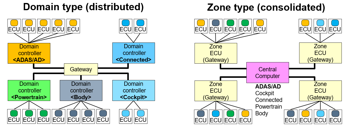
| Configuration | Connection | Network |
|---|---|---|
| Domain type | Consolidates domain-specific ECUs for each category (domain) All domains are connected via the Gateway Data processing is performed in each domain-specific ECU |
Common network standards are used for communication between sensors and domains Common network standards are used for communication between the domains and Gateway |
| Zone type | Consolidates ECUs of different categories in each zone such as the front and rear of the vehicle Consolidates data from each zone to the Central Computer Integrates and concentrates data processing in the Central Computer |
There is a mixture of different network standards for communication between sensors and zones Common network standards are used for communication between the zones and Central Computer |
 Explore products:
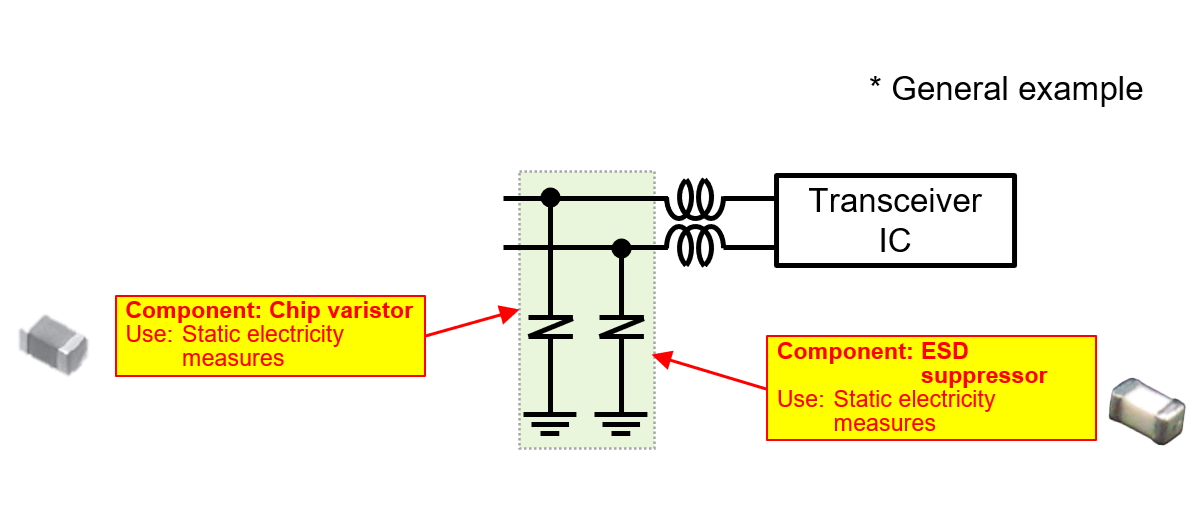
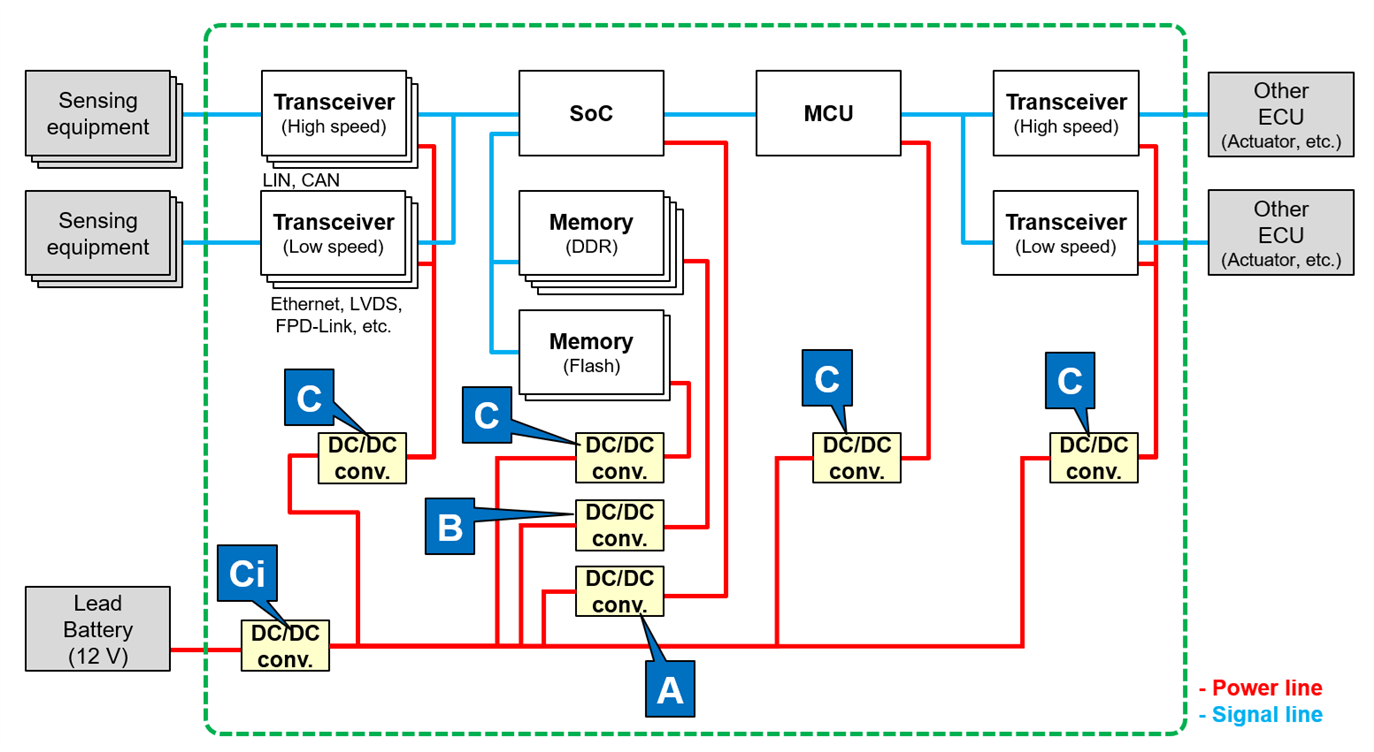
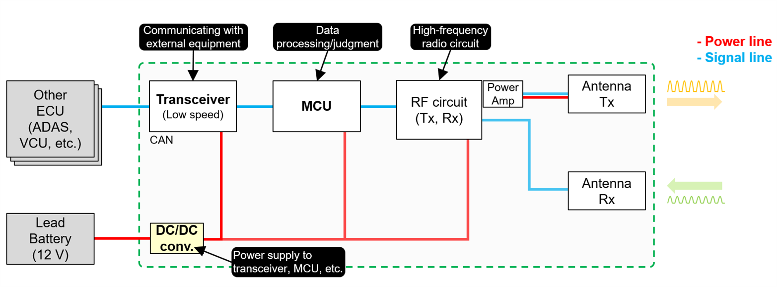
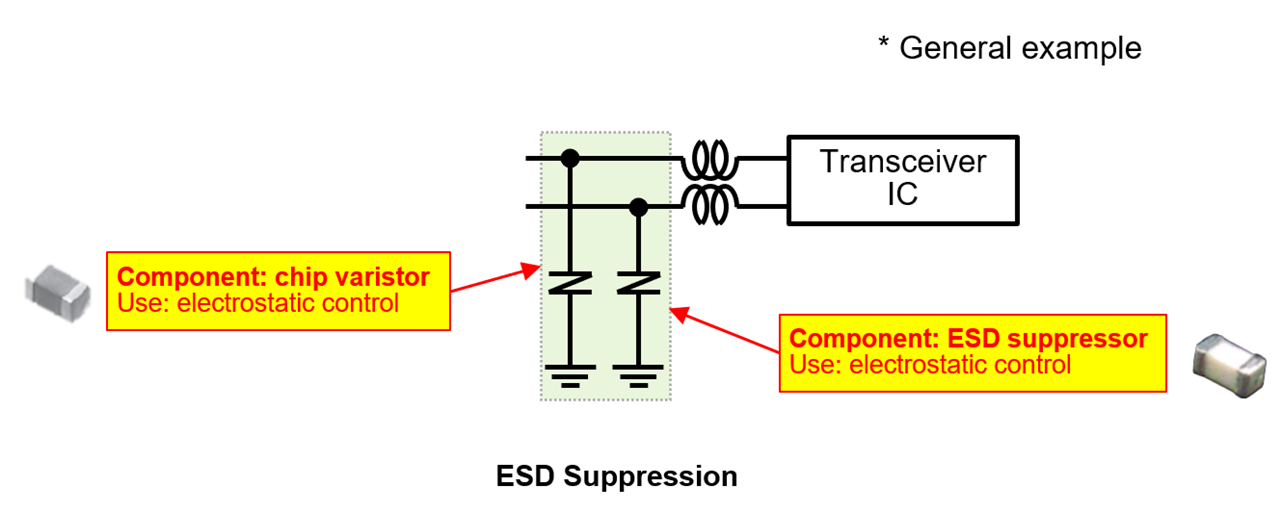
Figure 4 Components used in a transceiver IF
| Type | Typical Use | Characteristics |
|---|---|---|
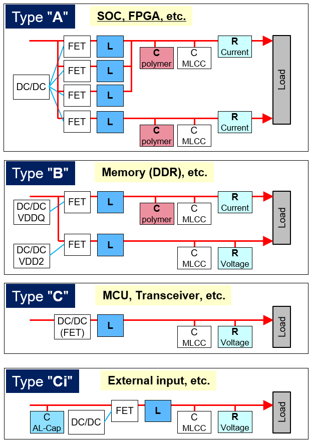
| A (Multiphase) | SoCs / FPGAs | Very high current, polymer capacitors + MLCCs |
| B | DDR memory | High ripple current, large‑capacitance smoothing |
| C | General rails | Standard DC/DC topology |
| Component Type | Key Features |
|---|---|
| Conductive Polymer Hybrid Capacitors | Low ESR, high ripple tolerance |
| Automotive Power Inductors | High current, low loss |
| High‑Precision Chip Resistors | High accuracy, high thermal reliability |
| Chip Varistors | ESD protection for various communication speeds |
| ESD Suppressors | Ultra‑low capacitance for high‑speed lines |
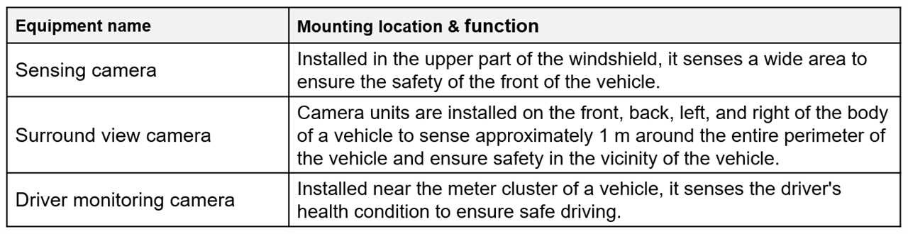
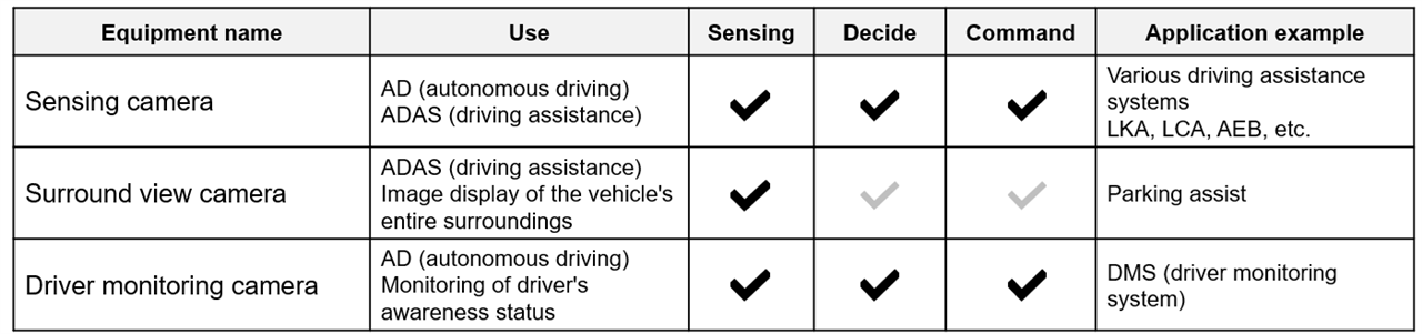
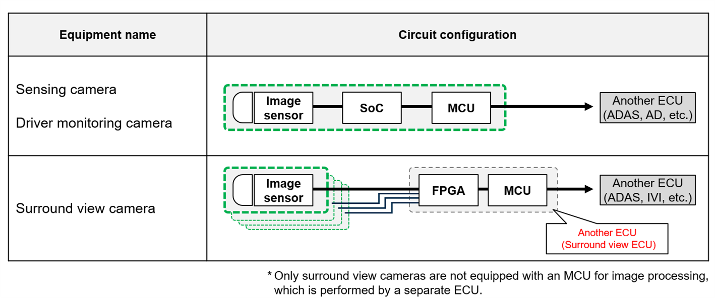
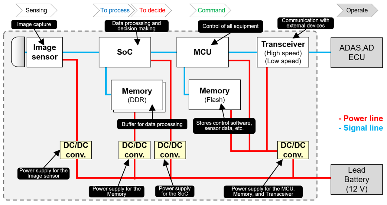
A camera ECU and surround view ECU are used to make up a surround view camera. Unlike other types of camera modules, multiple camera units are mounted on a vehicle to make up the surround view camera. Therefore, transceiver circuits must communicate larger amounts of data. An FPGA is used to integrate the acquired image data into one, where image processing is performed at high speed.
Other configurations are the same as those of sensing cameras and driver monitoring cameras.
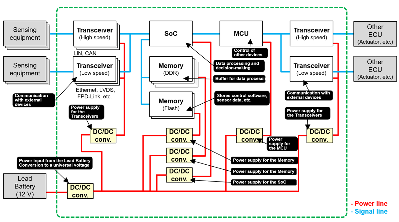
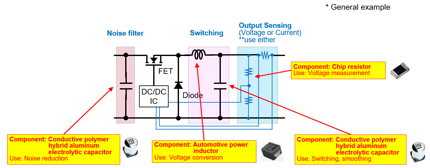
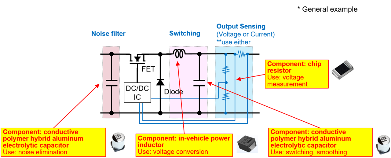
Components used in a DC/DC converter

LiDAR (Light Detection and Ranging) is a sensing technology that measures the distance to objects by emitting laser pulses and capturing the reflected light. The combination of emission direction and time‑of‑flight enables the generation of a high‑resolution 3D point cloud, which is widely used in ADAS and autonomous driving systems. As vehicle automation advances, the adoption of LiDAR is expected to grow steadily.
| Optical element | Optical axis varying method | Type | Scanning |
|---|---|---|---|
| LD, PD | Mechanical method | Rotation by a motor | A number of LDs and PDs are rotated by a motor to scan the whole area. |
| Polygon mirror | Respective optical axes of a single LD and a single PD are varied by a polygon mirror in scanning. | ||
| Non-mechanical method (solid-state) | MEMS mirror | Respective optical axes of a single LD and a single PD are varied by a MEMS mirror in scanning. | |
| Phased array | Respective optical axes of a single LD and a single PD are varied by a waveguide in scanning. | ||
| Flash | Light from a light source, such as an LED, is emitted over a wide area, and reflected light is collectively scanned by an array of PDs. |
By repeatedly scanning in multiple directions, LiDAR creates a point cloud.
This data is used to:
As autonomous driving levels increase, LiDAR systems must meet three key requirements:
| Requirement | Reason |
|---|---|
| Higher power | Higher‑resolution sensing increases CPU load and power demands. |
| Faster communication | High‑frequency and high‑speed data transfer is essential to process large point clouds. |
| Smaller size & lighter weight | Vehicles incorporate more sensors, requiring miniaturized components. |
A LiDAR unit typically consists of:
High‑performance LiDAR requires stable, low‑noise power.
| Function | Component | Key Features |
|---|---|---|
| Noise filtering & smoothing | Conductive polymer hybrid aluminum electrolytic capacitor | Low ESR, high ripple tolerance, excellent high‑frequency behavior |
| Voltage conversion | Automotive power inductor | High current capability, low loss, low ACR |
| Voltage measurement | High‑precision chip resistor | Low resistance tolerance, low TCR for accurate control |
Because communication lines are exposed to ESD, protection devices are critical.
Key points:
Reflected laser light is weak and must be amplified with high precision.
Why they matter:
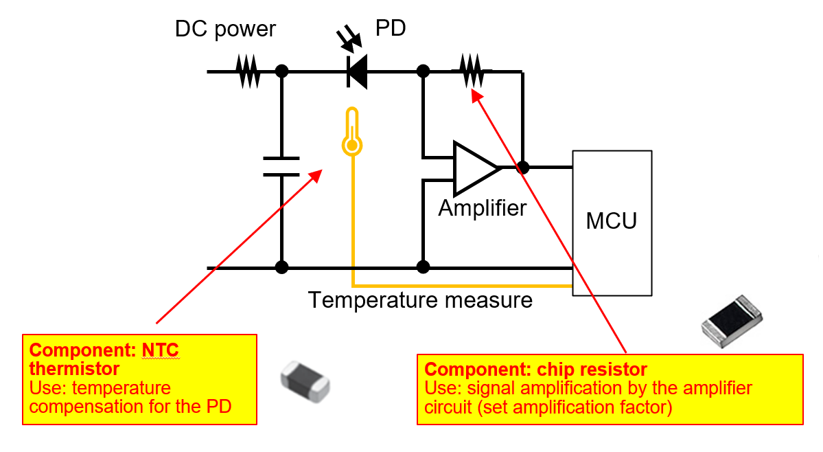
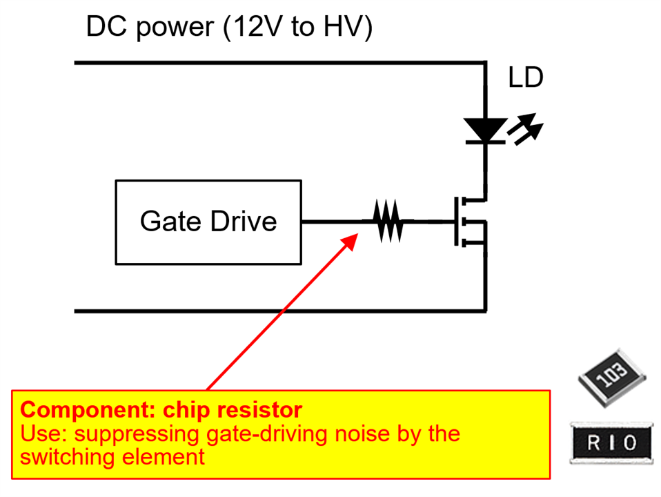
A GaN FET is typically used to deliver high‑speed, high‑power pulses.
Key advantage:
As autonomous vehicles adopt more LiDAR units, the demand for electronic components offering:
will continue to grow. Panasonic Industry offers a broad portfolio—including hybrid capacitors, automotive inductors, high‑precision resistors, varistors, ESD suppressors, and thermistors—that aligns well with these requirements.
| Component | Feature | Large current | Low loss | High frequency | Small size | High precision |
|---|---|---|---|---|---|---|
| Conductive polymer hybrid aluminum electrolytic capacitor | Low ESR High reliability |
 |
|
|
|
|
| Automotive power inductor | Large current, low loss High reliability |
|
|
|
|
|
| High precision, high resistance to heat | |
|
||||
| Chip varistor | Small and light | |
||||
| ESD suppressor | Low capacitance Ultrafast data I/F |
|
|
|||
| NTC thermistor (chip type) | Small, high resistance to heat | |
|
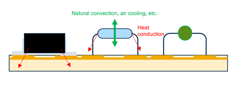
Heat effect image of resistor with leads

| Method | Advantages | Limitations |
|---|---|---|
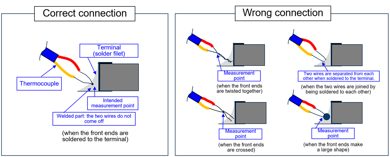
| Thermocouple | High accuracy, direct measurement | Requires physical contact; heat conduction through wires may distort readings |
| Infrared thermography | Contactless, easy to use, wide temperature range | Cannot measure through glass; requires high surface emissivity (may need black coating) |
 Browse Panasonic chip resistors on Element14
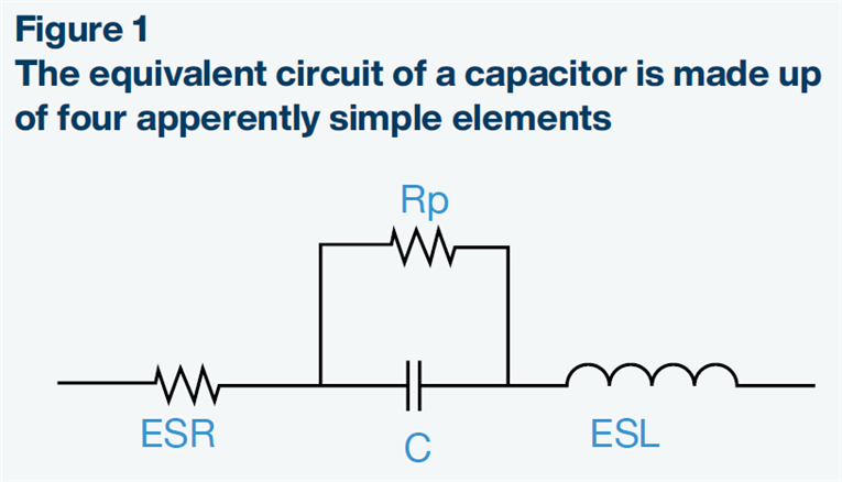
ESR represents the resistive component within a capacitor’s equivalent circuit. It influences:
Panasonic offers one of the industry’s most comprehensive portfolios of low ESR electrolytic capacitors, available in THT (Through-Hole) and SMD (Surface-Mount) configurations.
| Component | Features | Large Current | Low Loss | Compact |
Small Size |
High Precision |
|---|---|---|---|---|---|---|
| Hybrid Aluminum Electrolytic Capacitors | Low ESR, High Reliability | |
|
|
|
|
| Automotive Power Inductors | High Current, Low Loss | |
|
|
|
|
| High-Precision & High-Power Chip Resistors | High Accuracy, Heat Resistance | |
|
|||
| Chip Varistors | Compact, Lightweight | |
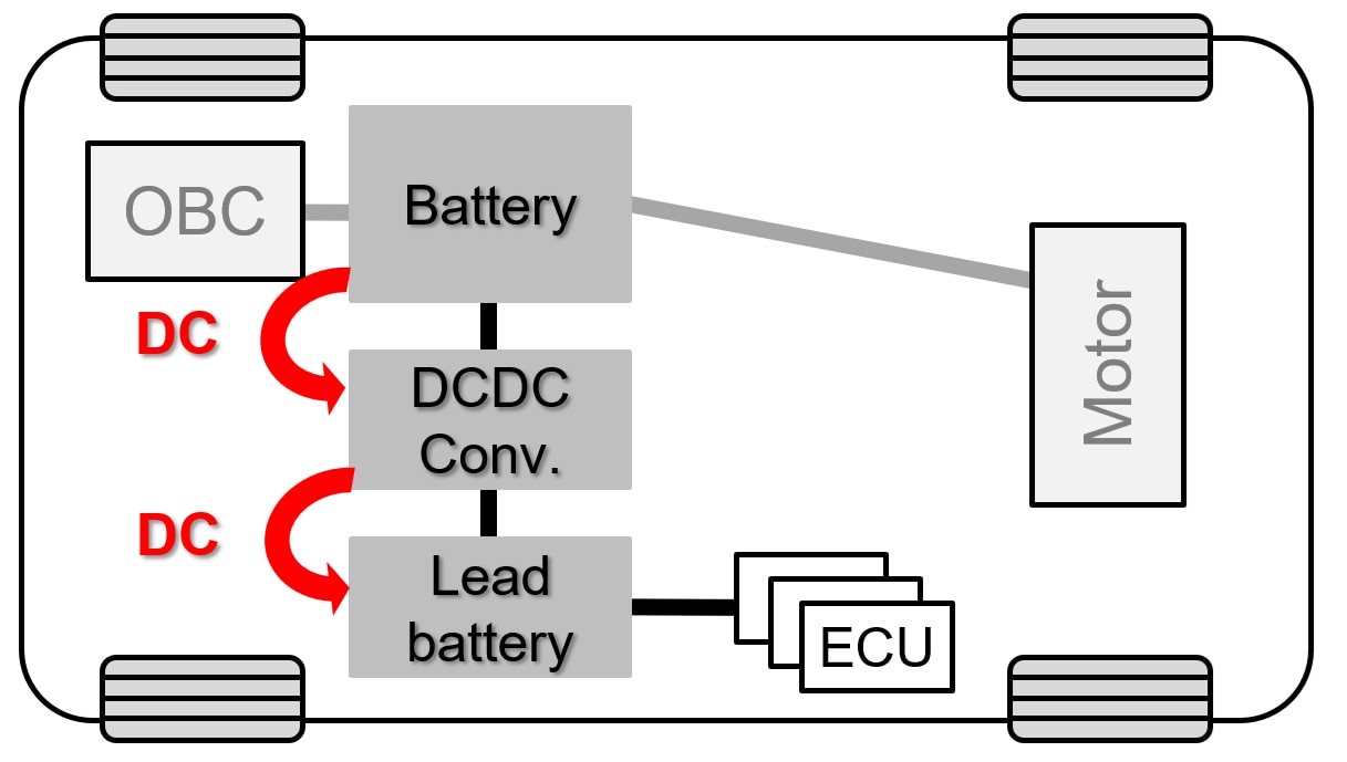
 What Does an On-Board Charger (OBC) Do?
 Types of EV Charging
・Normal charging
In normal charging, the battery is charged to full. The battery of an EV is charged with AC voltage from a private residents' charging equipment or a public charging station. Generally, charging the battery fully takes about eight hours. In the case of normal charging, the OBC incorporated in the vehicle converts AC voltage into DC voltage applicable to the vehicle battery.
・Quick charging
Quick charging is charging to refill the battery in a short time. In quick charging, the charging station supplies DC voltage corresponding to the battery voltage, charging up the vehicle battery in a short time by quickly feeding the battery with large power. Quick charging, in general, takes about 30 minutes to 1 hour to finish, depending on the battery capacity. You will find those chargers for EVs in a lot of expressway rest areas, commercial establishments, etc.
| Charging Type | Power Source | Location | OBC Usage | Charging Time | Purpose |
|---|---|---|---|---|---|
| Normal Charging | AC (200V/400V) | Home, Office | Converts AC to DC | ~8 hours | Full battery charge |
| Fast Charging | DC (direct output) | Highways, Commercial Facilities | Not used | ~30–60 minutes | Quick top-up |
 Battery Capacity & OBC Output
 Market Trends & Component Requirements
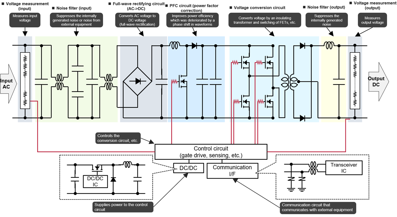
 Panasonic Components for OBC Systems
| Component | Features | High Voltage | High Current | Low Loss | Compact | Heat Resistant | High Precision |
|---|---|---|---|---|---|---|---|
| Hybrid Aluminum Electrolytic Capacitors | Low ESR, High Reliability | |
|
|
|
|
|
| Automotive Power Inductors | High Current, Low Loss | |
|
|
|
||
| High-Precision & High-Power Chip Resistors | High Accuracy, Heat Resistance | |
|
|
|
|
|
| Chip Varistors | Compact, Lightweight | |
|||||
| Automotive Film Capacitors | High Reliability | |
|
 Explore Panasonic’s OBC Solutions
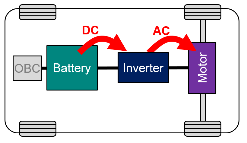
Explore Panasonic’s inverter-ready components on https://www.element14.com/ and accelerate your EV innovation today.| Component | Feature | High Voltage | Large Current | Low Loss | Miniaturization | High Heat Resistance | High Precision |
| Film Capacitors | High reliability |  |
 |
||||
| Conductive Polymer Hybrid Aluminum Electrolytic Capacitor | Low ESR High reliability |
|
|
|
|
|
|
| Power Inductor for Automotive Application | Large current, low loss High reliability |
|
|
|
|
||
| Chip Resistor | High precision, high resistance to heat | |
|
|
|
|
|
| Chip Varistor | Small and light | |
|||||
| NTC thermistor | Small, high resistance to heat | |
|
|
| Component | Feature | High voltage | Large current | Low loss | Miniaturization | High heat resistance | High precision |
| Film Capacitors (Automotive, Industrial and Infrastructure Use) | High reliability |  |
 |
||||
| Conductive Polymer Hybrid Aluminum Electrolytic Capacitors | Low ESR High reliability |
|
|
|
|
|
|
| Power Inductors for Automotive application | Large current, low loss High reliability |
|
|
|
|
||
| High Precision Chip Resistors Small & High Power Chip Resistors |
High precision, high resistance to heat | |
|
|
|
|
|
| Chip Varistor | Small and light | |


