Application Note
The SPoE Interface from an EMC Perspective
ANP141 by Adrian Stirn
1. INTRODUCTION
There are many possible applications for the 10 Mbit/s SPE interface with integrated power transmission, such as operating sensors over larger distances. This Application Note analyzes the EMC performance of the reference design RD041.
1.1 Brief description of the SPoE reference design
The reference design RD041 is an Ethernet interface that transmits data over a two-wire line while supplying power and is known as “Single Pair Ethernet (SPE)” with “Power over Data Lines (PoDL)” (see Figure 1). SPE enables Ethernet communication with just a single wire pair, making it ideal for space-saving applications in industry, the automotive industry, and in IoT devices. PoDL extends Power over Ethernet (PoE) to SPoE, enabling power and data transmission over a single twisted wire pair, simplifying installations and reducing costs.
1.2 Test setup for evaluating EMC performance
The devices additionally connected from Figure 2 serve as auxiliary equipment. The transmission path between the PD and PSE can be a shielded SPE cable or an unshielded twisted-pair cable. Laptop 1 is connected to the PD via a shielded 10 Mbit/s Ethernet interface. It obtains its IP address from the DHCP server (WiFi router) via the SPoE interface, which connects the PSE and PD. The PD is powered by the PSE board. The PSE part of the reference design has a 24 V input, which powers the SPoE reference design. In the reference design, this connection is configured as a port to a local DC power supply network. The 10 Mbit/s interface is connected to the router via a shielded Ethernet cable and then on to the laptop for evaluation. Both laptops obtain their IP addresses from the DHCP server. The reference design is therefore ready to use and can, as an adapter, extend an internet connection by plug-and-play.
For EMC testing, the reference design, consisting of two boards (Powered Device - PD and Power Sourcing Equipment - PSE), is operated with a defined transmission path as the test specimen.
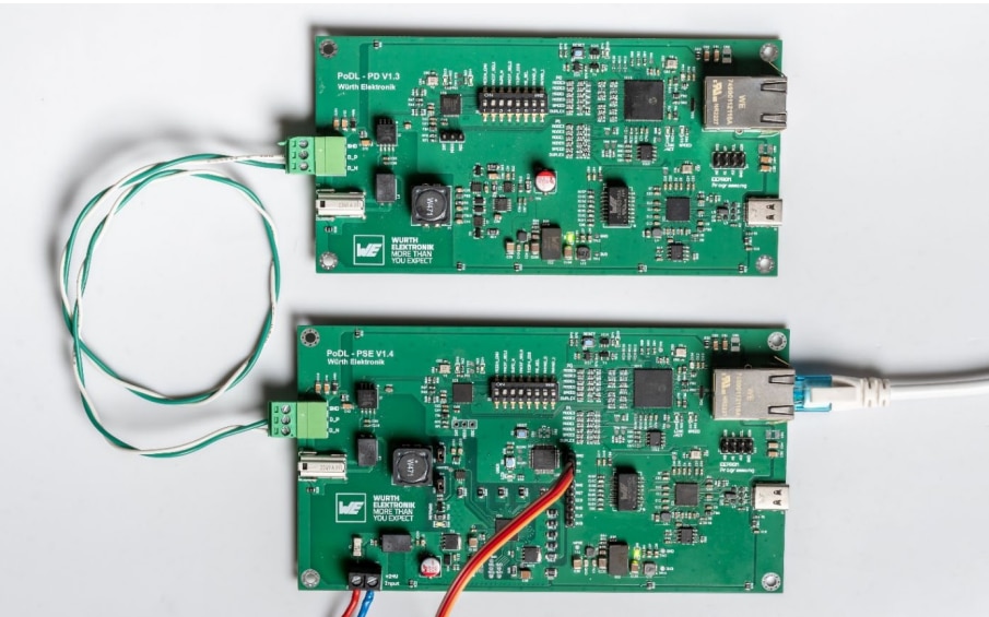
Figure 1: PSE (board in photo below) and PD (board in photo above) putting RD041 into operation
The devices additionally connected from Figure 2 serve as auxiliary equipment. The transmission path between the PD and PSE can be a shielded SPE cable or an unshielded twisted-pair cable.
Laptop 1 is connected to the PD via a shielded 10 Mbit/s Ethernet interface. It obtains its IP address from the DHCP server (WiFi router) via the SPoE interface, which connects the PSE and PD. The PD is powered by the PSE board.
The PSE part of the reference design has a 24 V input, which powers the SPoE reference design. In the reference design, this connection is configured as a port to a local DC power supply network. The 10 Mbit/s interface is connected to the router via a shielded Ethernet cable and then on to the laptop for evaluation. Both laptops obtain their IP addresses from the DHCP server. The reference design is therefore ready to use and can, as an adapter, extend an internet connection by plug-and-play.
1.3 Test software and performance criteria
Laptop 1 acts as a server which sends known test data to Laptop 2. This evaluates the transmission error rate and transmission speed using a Windows application. This monitoring application has already been used successfully in ANP116 and ANP122, the Application Notes for the GB Ethernet design.
Figure 3 shows that the transmission achieves an average payload of just under 9 Mbit/s. In the selected test case, the packages have a shorter transmission time than in the tests on the Gigabit Ethernet interface. During testing, a measurement and exposure time of one second can therefore be used.

Figure 2: Test setup for performance evaluation of the SPoE reference design
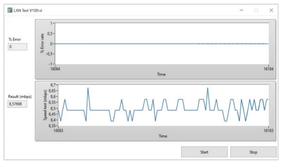
Figure 3: Monitoring the SPoE interface. PSE and PD are integrated into the network via an Ethernet interface.
During immunity testing, the performance of the reference design is evaluated using criteria from Table 1.
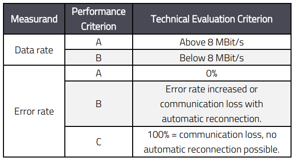
Table 1: Performance criteria of the SPoE reference design.
When evaluating the performance criteria, the auxiliary equipment also has a relevant impact on the performance of the transmission path. For example, the transmission error rate increased when a WiFi interface was used between the router and Laptop 2 instead of a shielded Ethernet cable.
1.4 Shield connection of the Ethernet interface
As shown in Application Note ANP116 , the following components are suitable for connecting the shield of the Ethernet socket to the ground plane (GND) of the board Figure 4.
- 2 x 10 nF X7R 1206 MLCC 100 V (885012208112).
- SMT varistor (82551600).
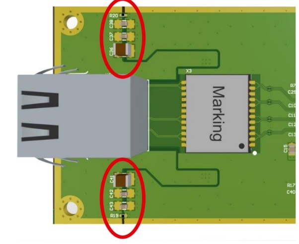
Figure 4: Shield connection of the Ethernet socket from ANP116 . An MLCC is used on each side; the varistor is not shown in the figure.
The shield connection is used for both the SPoE interface and the 10 Mbit/s Ethernet interface. The varistor is not shown in Figure 4. It can be placed parallel to the capacitor on one side. The USB interface on the boards is not used for the analyses in this Application Note.

Figure 5: Block diagram for testing radiated emissions and immunity
2. EMISSION OF THE REFERENCE DESIGN
The emissions from the reference design in the configurations described are analyzed below. In the emission measurements according to CISPR 32 (International Special Committee on Radio Interference), the USB interface is not used; communication only takes place via the Ethernet and SPoE interfaces.
2.1 Radiated emissions
To test the radiated emissions, the PD and PSE are operated and tested together. The cable length at the SPoE interface is 1 m, lying horizontally in the space between the two boards during emissions testing.
Test setup
The PSE is powered by a 24 V source and feed-through filters from a lab power supply located outside the fully anechoic chamber. The PSE and PD are located in the fully anechoic chamber, with the PSE connected to an Ethernet fiber optic converter via a shielded 10 Mbit/s Ethernet cable, which establishes a connection to the router and Laptop 2 outside the measurement chamber. The PD is connected to Laptop 1 via a shielded Ethernet cable located in a shielding box.
The setup from Figure 5 ensures that interference from the router or the laptops is not measured during emissions testing. As this setup is also used for radiated immunity testing, the laptops and the router are protected from interference through the electric field generated in immunity testing.

Figure 6: Testing the radiated emissions from the SPoE reference design in the fully anechoic chamber
The test in the left photo in Figure 6 is carried out using an unshielded twisted-pair cable and in the right photo with a shielded SPE cable. The shielded box is not shown.
Results of radiated emissions testing
The radiated emissions from the reference design are measured as shown in Figure 5. The emission spectrum from the reference design in Figure 7 is at least 9 dB below the limit for both cable types used, and the results are comparable. Thus, the radiated emissions are extremely low even when using unshielded twisted-pair cables.
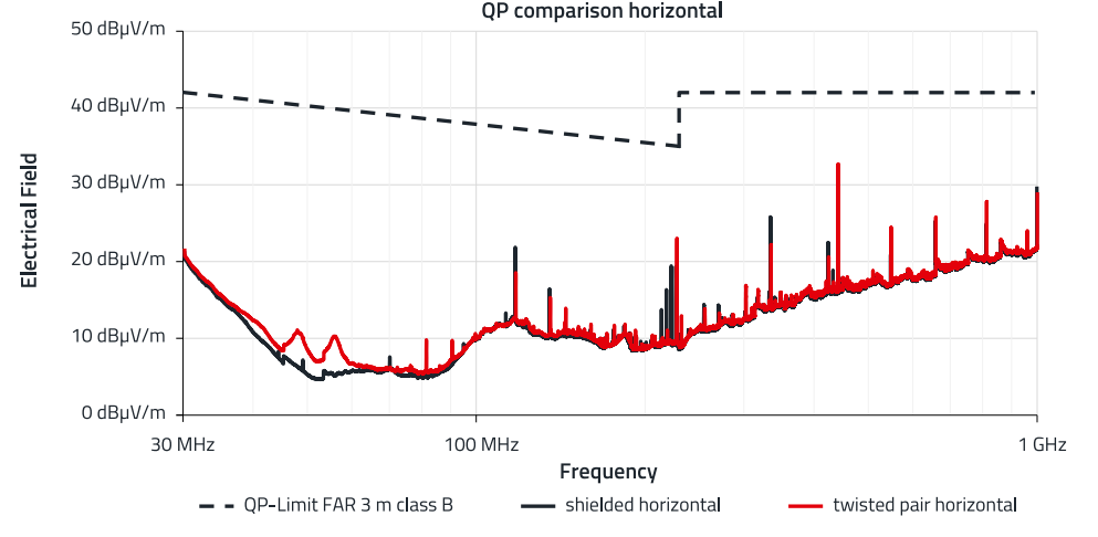
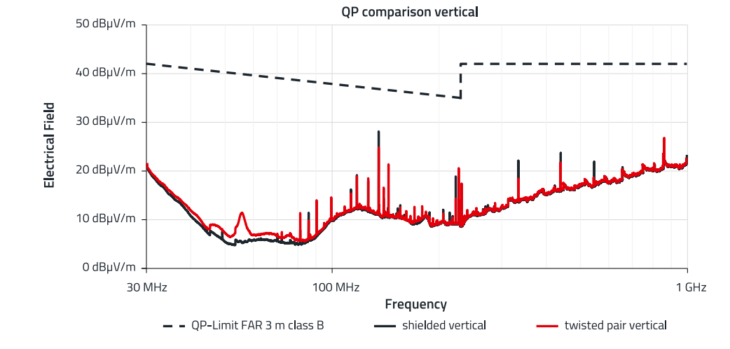
Figure 7: Comparison of the radiated emissions from the SPoE reference design when using shielded SPE cable or unshielded twisted-pair cable
2.2 Radio interference voltage
The test setup for radio interference voltage measurement is described and the results presented as follows.
Test setup
The PSE and PD may be spatially separated in the subsequent setup and are therefore tested individually. The DC input of the PSE is to be tested as a potential DC network input, and the Ethernet cables for the 10 Mbit/s Ethernet interface and SPoE interface, should be considered as a long network cable. The emissions from the DC input on the PSE is measured using a CISPR 16 type 50 µH Artificial Mains Network (AMN), while the emissions from the network ports are measured using a 150 Ω Coupling Decoupling Network (CDN), which functions as an Asymmetric Artificial Network (AAN). The test setups for measuring the radio interference voltage on the PSE and PD are shown in Figure 8 and Figure 9.
A CDN T2 is used for testing the SPoE interface with an unshielded twisted-pair cable, while measuring interference on the shielded SPoE interface involves testing using a custom-built CDN for shielded SPE cables. Interference on the shielded Ethernet cable is measured using a CDN for shielded Cat5e cables. Network simulations and CDNs must always be terminated with 50 Ω in the test setup (either through the measuring receiver or with a 50 Ω resistor).
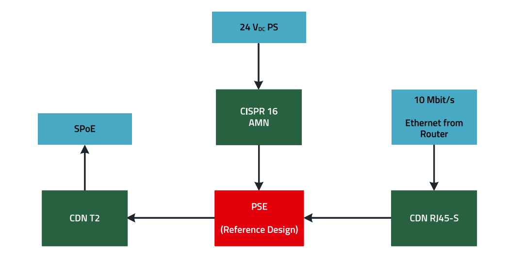
Figure 8: Test setup for measuring the conducted interference voltage on the PSE.
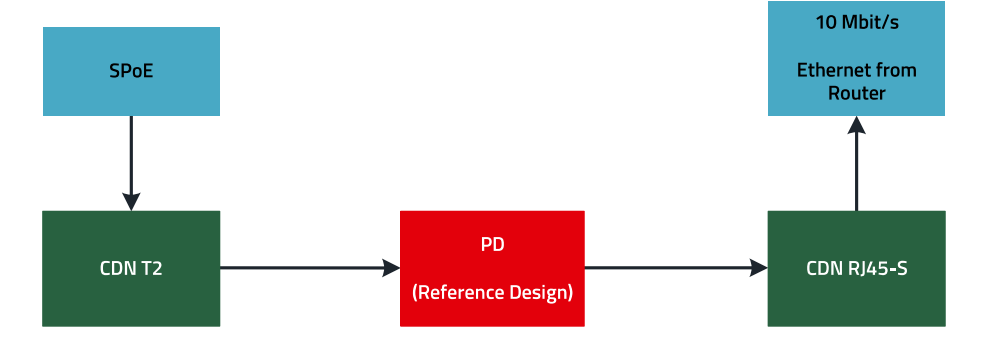
Figure 9: Test setup for measuring the conducted interference voltage on the PD
Figure 10 shows a photo of this test setup.
Results of conducted emissions testing
The results of conducted emissions testing are presented below. As the results at the DC port on the positive supply line show no relevant difference from the negative supply line, only the results of the positive supply line are shown for clarity. The results from the quasi-peak and average detector are presented separately. The graph takes the limit for low-voltage connections in residential areas for comparison. This is lower than the threshold for DC networks – if the test specimens meet the requirements for AC networks, this limit is also automatically below the limits for DC networks. All limit values shown in the emission graphs are valid for residential areas – or according to product standard class B.
Power Source Equipment
The interference voltage measurements of the PSE are carried out in the test setup from Figure 10. The following graphs compare the conducted emissions with a shielded SPE cable and an unshielded twisted-pair cable on the PSE.
The conducted interference on the DC port increases across the entire frequency range if an unshielded twisted-pair cable is used instead of a shielded SPE cable. However, the relevant peaks change slightly, and emissions remain more than 10 dB below the limits in both configurations as shown in Figure 11.
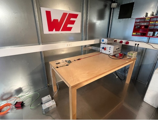
Figure 10: Measurement of conducted emissions at the PSE board of the SPoE reference design.
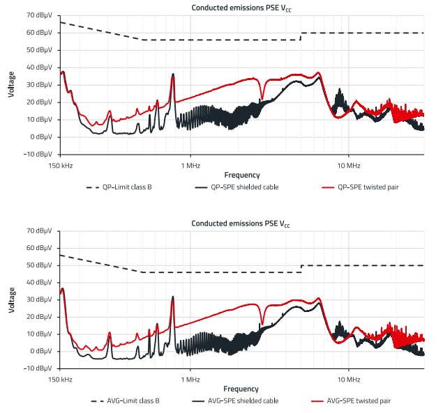
Figure 11: Results of the radio interference voltage measurement at the DC port of the PSE. The results from the quasi-peak detector are shown at the top and the results from the average detector at the bottom
A similar behavior can also be observed in Figure 12 in the measurement results for interference voltage on the SPoE interface. When using the unshielded twisted-pair cable, emissions increase across a wide frequency range. Only the conducted emission results on the shielded Ethernet cable, as shown in Figure 13, change slightly when the reference design is operated with an unshielded twisted-pair cable instead of a shielded SPE cable.
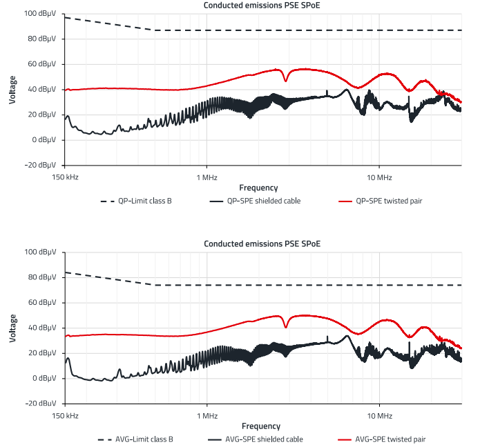
Figure 12: Results of conducted emissions on the SPoE interface of the PSE. The results from the quasi-peak detector are shown at the top and the results from the average detector at the bottom
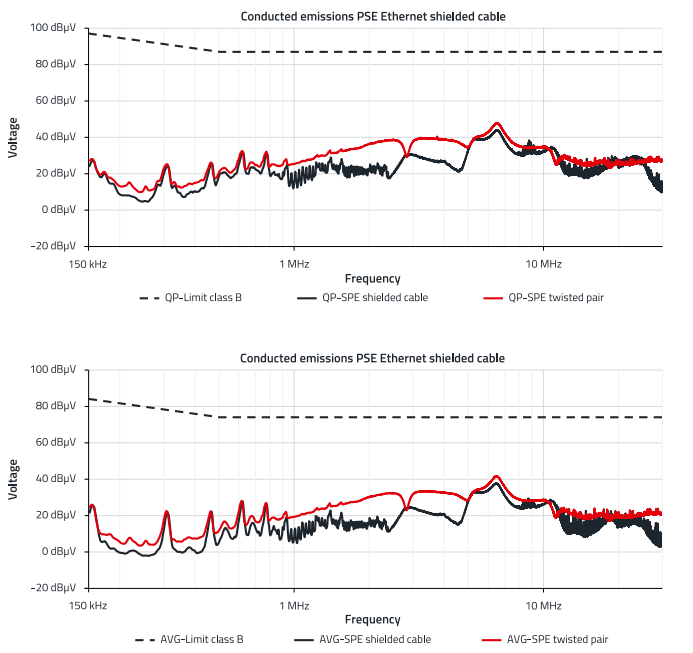
Figure 13: Results of the conducted emissions on the Ethernet interface of the PSE when using a Cat5e SF/UTP cable. The results from the quasi-peak detector are shown at the top and the results from the average detector at the bottom.
Powered Device The PD is tested in a similar way to the PSE, but the measurement of the DC port is omitted. For the PD, the measurement results for the reference design change to the same extent on the SPoE interface (Figure 14) and Ethernet interface (Figure 15) when changing from a shielded to an unshielded SPE cable. The emissions increase across the entire frequency range when using unshielded cables but remain well below the residential area limit.
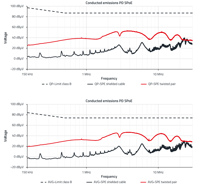
Figure 14: Results of conducted emissions on the SPoE interface of the PD. The results from the quasi-peak detector are shown at the top and the results from the average detector at the bottom
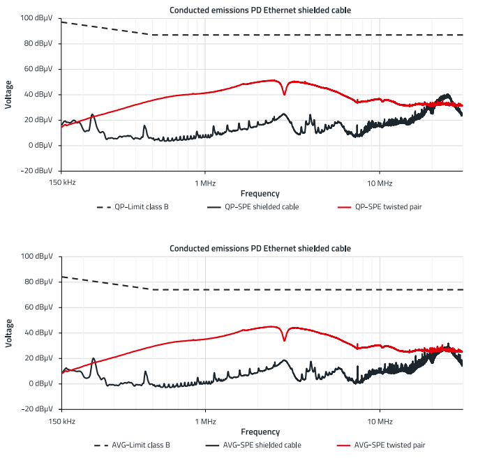
Figure 15: Results of the conducted emissions on the Ethernet interface of the PD when using a Cat5e SF/UTP cable. The results of the quasipeak detector are shown at the top and the results of the average detector at the bottom.
2.3 Summary of emissions testing
The SPoE reference design is characterized by low radiated and conducted emissions. Despite the open boards without shielding enclosures, the emissions results are significantly below the EMC limits for residential areas. Even with an unshielded twisted-pair cable, the results for the SPoE interface are significantly below the EMC limits in all measurements. From an emissions testing perspective, shielding of the SPoE interface is therefore not required.
3. IMMUNITY OF THE REFERENCE DESIGN TOWARDS CONTINUOUS INTERFERENCE
The length of the SPE cable is at least 5 m during the immunity tests. In some cases, the 5 m cable length is also routed on the AE (auxiliary equipment) side of the coupling networks. As the cables of the reference design are long, the boards are tested individually during the conducted emission tests.
3.1 Radiated immunity
For testing radiated immunity according to IEC 61000-4-3 in the frequency range from 80 MHz to 6 GHz, the setup described in Figure 5 from section 2.1 (Test setup) is used. The length of the SPE cable is 5 m and the excess cable length in the test setup lies on the floor of the anechoic chamber. The reference design is tested with both a shielded SPE cable and with an unshielded twisted-pair cable at the maximum field strength specified in Figure 16. The function of the reference design is not affected, and it passes the immunity tests at high test levels in performance criterion A.
3.2 Conducted immunity against induced RF interference
The two boards are individually tested for immunity in the frequency range from 150 kHz to 80 MHz according to IEC 61000-4-6. The Ethernet, SPE, and DC cables are to be considered long in a potential application and are therefore tested according to the setup shown below.
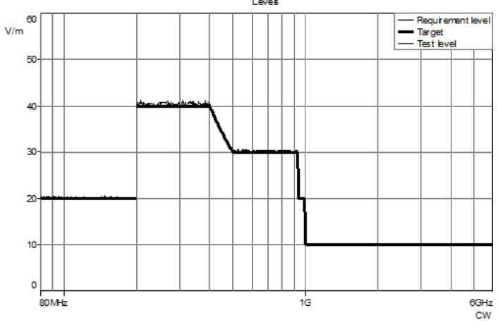
Figure 16: Maximum test level of the radiated immunity test
Test setup
Two 12 V lead-acid batteries are used to power the PSE to ensure a stable supply that is not affected by the test. Despite decoupling through CDNs, lab power supplies can be affected by interference in the shielded chamber and this can destabilize the output voltage and a fluctuation in the DC voltage can lead to errors in interpreting the immunity criteria.
The cables between the device-under-test side of the CDNs and the test specimens are less than 30 cm long, ensuring that the distance between the CDN and the device meets the normative requirements. The Ethernet interface configured at 10 Mbit/s is tested using a CDN for shielded cables. For testing the SPoE interface with unshielded cables, a CDN T2 is used, and with a shielded SPE cable, a custom-built CDN-S suited to the type of cable is used. The set-up for testing conducted immunity is shown in Figure 17 and Figure 18.
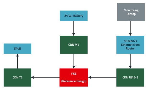
Figure 17: Test setup for conducted immunity testing on the PSE
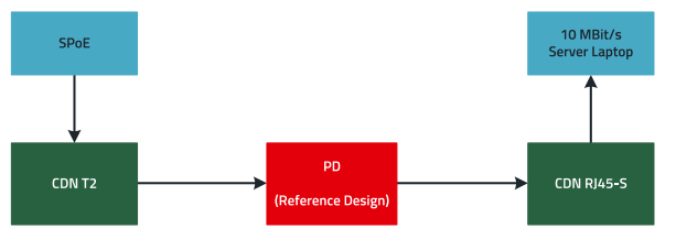
Figure 18: Test setup for conducted immunity testing on the PD
Termination of a CDN in the test setup with 50 Ω is carried out according to the specifications in the base standard IEC 61000-4-6. The setup for conducted immunity testing of the PSE board with an unshielded twisted-pair cable is shown in Figure 19. On the AE side of the CDN T2 (right CDN in Figure 19), an additional 5 m cable is connected to the PD, decoupled from the test specimen. When coupling to the power supply line, the CDN on the shielded Ethernet cable is terminated with 50 Ω.
Results of conducted immunity testing
Power Source Equipment
The PSE board is tested at a level of 20 V with both a shielded SPE cable and an unshielded twisted-pair cable as the connection between the PSE and PD. Here the interference is coupled to the power input, the Ethernet interface, and the SPE interface, respectively. With both shielded and unshielded SPE cables, the board's function remains unaffected during testing of all inputs.
Powered Device
The PD board is tested the same way as the PSE board. Testing of the power supply line is omitted here, however. The PD board is also unaffected by test levels of 20 V in the conducted immunity test.
3.3 Summary of continuous immunity tests
The function of the SPoE reference design (both boards) is unaffected by continuous interference during the immunity tests, and the reference design passes the immunity tests at high test levels in performance criterion A. The requirements for immunity to continuous disturbances for industrial products are thus fulfilled, and even over-testing at twice the test level shows no performance losses. From the perspective of these immunity tests, a shielded cable is not needed for the SPoE interface.
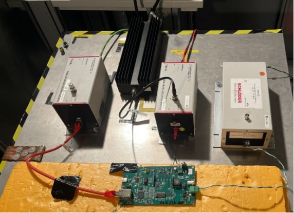
Figure 19: Conducted immunity testing of the PSE board
4. IMMUNITY OF THE REFERENCE DESIGN TO TRANSIENT INTERFERENCE
While the SPoE reference design passes emission and immunity tests against continuous interference without restrictions and with very good performance, protecting the board against transient interference is more challenging in its implementation.
4.1 Transient immunity, burst
Immunity testing is carried out separately for the PD and PSE, as outlined in the previous section. Coupling is applied to all interfaces due to potential cable length, except for the USB interface, which is defined for cable lengths under 3 m.
Test setup
The burst is coupled to the DC line of the PSE board using a CDN, simulating the connection to a DC power supply network. If an isolated supply is assumed, the burst test is carried out on the supply lines using a capacitive coupling clamp. The data lines are coupled using the capacitive coupling clamp. The PSE and PD are tested one after the other. During testing, the shielded 100 Mbit/s Ethernet cable on the auxiliary equipment side is decoupled either using a fiber optic converter or a CMAD. The DC interface is decoupled from the power supply using the burst CDN or is operated with lead-acid batteries. The laptop from Figure 21 is battery operated and disconnected from the mains for better decoupling. The laptop from Figure 20 is decoupled using a fiber optic transformer.
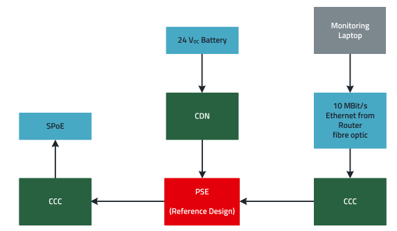
Figure 20: Test setup for immunity testing against bursts on the PSE.
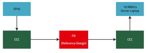
Figure 21: Test setup for immunity testing against bursts on the PD
The board’s overvoltage protection devices can only work satisfactorily with a proper reference ground. For transient testing, the ground shielding ring of the board is therefore connected to the system's reference ground – simulated by a wire strand connection between the board’s shield ground and the reference ground (see Figure 22). This simulates a connection with an earthed chassis ground in a possible application. The interference comes from the interfaces and is then passed to the shielding ring of the board, and from there to the chassis. From here, the interference is passed to the reference ground in the test setup, either capacitively or via an earth connection.
However, the SPoE standard specifies a decoupled supply for the interface. For this reason, the test setup can also be isolated from the surroundings according to the Figure 23 as follows. All connected interfaces are operated in isolation for this reason. This is achieved by powering with batteries; the laptops are also only used in battery mode, the Ethernet interfaces are optically decoupled, and the shielding ring of the boards is not earthed. In this case, burst coupling takes place solely using a capacitive coupling clamp, also on the supply line of the PSE.
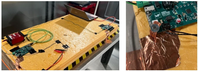
Figure 22: The left photo shows the test setup of the SPoE reference design for testing against fast transient interference, and the right photo shows the ground connection
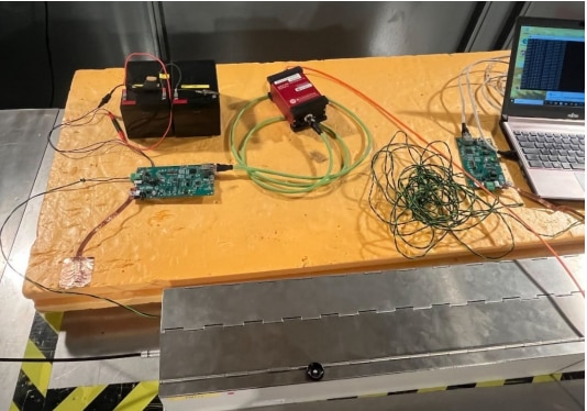
Figure 23: Burst testing with the isolated SPoE interface
Special case: Results of burst testing for non-isolated boards
The overvoltage protection devices are connected via the ground shielding.
Power Source Equipment
When bursts are coupled to the 24 VDC supply line via a CDN, the PSE behaves identically with both shielded and unshielded SPoE cables. At a test level of 500 V, the operation of the SPoE reference design is not disturbed. At test levels of 1 kV and 2 kV, the error rate increases from 0% to 10%, and the transmission speed decreases, as shown in Figure 24.
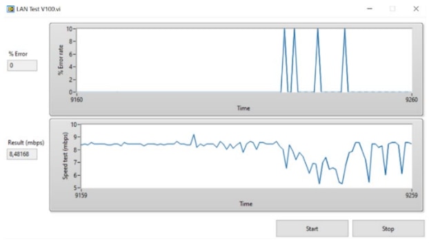
Figure 24: Performance criterion B during burst testing.
This corresponds to performance criterion B. Assuming the SPoE link is operated as a standalone product, this is considered sufficiently good performance from an EMC standardization perspective. Transient pulses do not occur continuously, which is why certain performance losses are acceptable, provided the test specimen returns to its pre-test operating state without user intervention. However, if the reference design is considered as part of an application, such as integrated into an industrial control system, it has to be ensured that the overall application meets performance criterion B. When integrating the reference design into an application, an increase in error rate and a reduction in transmission speed should therefore be acceptable. In an industrial system, for example, a reduced transmission speed in the control system could trigger an emergency stop, requiring authorization from the operator to resume, which would correspond to performance criterion C. At the same time, the interface, as a standalone application, still meets performance criterion B. It is assumed that the SPoE reference design will be integrated into a complete application, so direct coupling to the supply is not expected. Moreover, the complete system must be considered, including the interface with relevant components and the upstream supply.
When coupling bursts to the SPoE interface and the Ethernet interface using a capacitive coupling clamp, performance criterion A is achieved at test levels up to 5 kV if a shielded SPE cable is used. If an unshielded twisted-pair cable is used, the immunity is significantly reduced. Figure 25 shows the active gas discharge tube (GDT) on the underside of the board during coupling using a capacitive coupling clamp on the unshielded twisted-pair cable at a test level of 1 kV, if the shielding ring is connected to the reference ground.
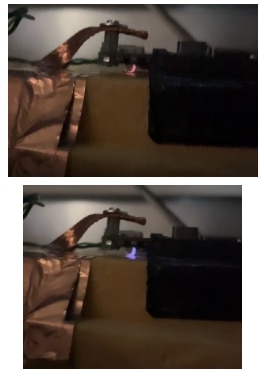
Figure 25: The gas discharge tube (GDT) passes a burst coupled with a capacitive coupling clamp to the SPoE interface which is operated with an unshielded twisted-pair cable.
When an unshielded twisted-pair cable is used, the burst test on the Ethernet line is passed at 1 kV using the capacitive coupling clamp, achieving performance criterion A. At test levels over 1 kV up to 4 kV, performance criterion B is achieved as shown in Figure 24. At a test level of 5 kV, a temporary connection reset occurs. However, the connection is automatically re-established after each burst packages, and the data packages continue to be transmitted.
When bursts are coupled to the unshielded twisted-pair cable using a capacitive coupling clamp, the system operates at 500 V at performance criterion B and occasionally has connection resets at a test level of 1 kV and above. At a test level of 1 kV, this disconnection is not permanent, and data transmission resumes at the end of the burst package. At a test level of 200 V, performance criterion A is achieved.
Powered Device
The behavior of the PD during burst testing is comparable to that of the PSE. The difference between using a shielded and an unshielded cable on the SPoE interface leads to significant performance variations during burst testing.
When a shielded SPE cable is used, the test passes performance criterion A at test levels up to 4 kV and performance criterion B at a test level of 5 kV. It makes no difference whether testing is carried out on the SPoE interface or the Ethernet interface with the capacitive coupling clamp. If an unshielded twisted-pair cable is used instead of a shielded SPE cable, the performance decreases significantly. At test levels of 500 V, performance criterion B is achieved. At a test level of 1 kV, brief interruptions occur in the SPoE connection, but data transmission resumes automatically at the end of the burst package without user intervention.
Results of the burst test for isolated operation
The boards are operated with an isolated supply voltage, as specified by the standard. This isolation must be provided separately in the design of the SPoE interface in the application. The tests in the isolated setup are particularly relevant for transient immunity using unshielded twisted-pair cables.
In the isolated setup, the Ethernet interface and SPoE interface behave the same when unshielded twisted-pair cables are used. For testing the Ethernet interface, performance criterion A is achieved at test levels up to 1 kV, and performance criterion B is achieved at 2 kV. The PSE also achieves this performance when the burst is coupled to the DC input using a coupling clamp. The SPoE interface achieves performance criterion A at a test level of 500 V and performance criterion B at a test level of 1 kV when using an unshielded twisted-pair cable.
4.2 Transient immunity, surge
As the data interfaces of the reference design, apart from the USB interface, may have cable lengths exceeding 30 m, sufficient immunity against transient surge pulses must be provided. Only limited transient protection is provided on the DC input of the PSE, as it is assumed that a power supply will be connected upstream in the later application. If the PSE of reference design RD041 is to be connected directly to a DC supply network, additional protective measures against transient pulses are required.
Test setup
During the surge test, the PSE is operated using either lead-acid batteries or a CDN decoupled supply voltage. Coupling to the shielded Ethernet cables is achieved through direct coupling. The auxiliary equipment and the test specimen must be galvanically isolated from ground for this purpose. This can be achieved by decoupling with fiber optic cables or by operating the laptops in battery mode without a power supply. The surge pulse is coupled to the balanced unshielded SPoE data line using CDN coupling with 42 Ω unbalanced coupling. As the data cable is twisted and balanced, it is assumed that surge pulse coupling is only unbalanced against ground in the application. The surge test with the unshielded twisted-pair cable is carried out in the isolated setup (Figure 26).
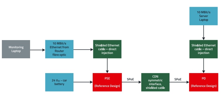
Figure 26: Test setup for immunity testing against surge pulses. The Ethernet interface is galvanically isolated
As an alternative to the test setup using an unshielded twisted-pair cable for the SPoE interface, testing can also be carried out with a shielded SPE cable (see Figure 27) using direct coupling. As is usual with direct surge coupling to the cable shield, all the laptops connected must also be decoupled in this case.
Results of surge testing in the non-isolated setup
If no importance is placed on isolation from the surroundings when setting up the surge test, and coupling is permitted, the performance for shielded SPE cables is described below. When using unshielded twisted-pair cables, a manual reset of the LTC 4926.1 is necessary in this operating mode.
Power Source Equipment
Surge testing using a shielded SPE cable can meet the requirements for industrial immunity. As previously mentioned, the supply voltage of the PSE is not tested. For testing the shielded Ethernet cable, performance criterion A is achieved at a test level of 1 kV. Surge coupling to the shielded SPE cable achieves performance criterion A at a test level of 500 V, and performance criterion B at a test level of 1 kV. The weak point in the application during surge testing is due to the LTC4296-1 multichannel SPoE PSE controller. For tests with levels above 1 kV, the voltage on the SPoE interface is briefly interrupted, or the IC requires an external reset.
Powered Device
The test results with a shielded SPE cable correspond to those of the PSE. The reason is that the surge from Figure 27 is fed from a ground bolt on the PSE to another on the PD. When testing the SPoE interface with shielded cable, both the PD and PSE are tested at the same time. The shielded Ethernet interface is tested at performance criterion A with a test level of 1 kV.
Results of the surge test in the non-isolated setup
If strict attention is paid to galvanic isolation and avoidance of coupling with the surroundings in the surge test setup, the performance improves noticeably. The tests are passed for both the PSE and PD at performance criterion A with test levels up to 1 kV, for both shielded SPE cables and unshielded twisted-pair cables. If decoupling from ground cannot be avoided in an application, software monitoring at the PSE can be used to restart power transmission after an interruption, thereby enhancing the performance of the interface when transient pulse is applied.

Figure 27: Surge coupling to the shielded SPoE interface. The PSE is galvanically isolated from ground via a surge CDN at the supply input (alternatively, battery operation).
4.3 Transient immunity, ESD
During ESD testing of a reference design, not the entire product is tested, but rather the focus is primarily on parts of the application that will be accessible later on. If the SPoE reference design is integrated into an application, the components on the board can no longer be touched, so ESD testing is carried out on the interfaces of the reference design.
Test setup
The PSE and PD are set up on a Teflon insulating mat on the horizontal coupling plane (HCP) of the ESD test bench. Both boards of the SPoE reference design are tested at the same time. The Ethernet interfaces are isolated during operation, either through a battery-powered laptop or an optical fiber link. The PSE is powered by lead-acid batteries.
Indirect discharge is carried out on the HCP and the vertical coupling plane (VCP). Additionally, testing is carried out on the shielded Ethernet interface by means of contact discharge on the Ethernet socket (Figure 28). The discharge is applied to the shielded SPE socket with both shielded and unshielded SPoE cables. When using unshielded cables (Figure 29), a connector is used that ensures contact protection of the electronics and contacts when operating the interface in an application.
For this reason, an ESD discharge is only simulated on the shielding ring near the connector on the board and not on the interface contacts.
As it is assumed that the supply is internal in a possible application, no discharge in the DC interface is tested. This interface is not accessible during operation if the chassis of the overall application is closed.
Results of ESD testing
For testing the indirect discharge on the HCP and VCP, performance criterion A was achieved at a test level of 4 kV, and performance criterion B at 6 kV. The performance was identical at the SPoE interface when using both cable types. If the indirect discharge is tested at 8 kV, connection to the Ethernet hub IC is briefly interrupted, but it is immediately re-established. When the discharge is applied to the socket shields, performance criterion A is achieved using a shielded SPE cable and a test level of 4 kV, and performance criterion B for levels up to 8 kV. If an unshielded twisted pair cable is used instead of a shielded cable, immunity to ESD decreases slightly, achieving performance criterion A up to 2 kV discharge. Between 2 and 8 kV, performance criterion B is achieved.
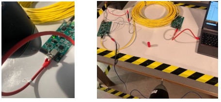
Figure 28: ESD testing of the SPoE reference design. Left: Contact discharge on the shielded Ethernet socket. Right: Indirect ESD testing using a horizontal coupling plane (HCP).
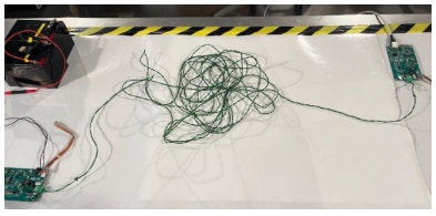
Figure 29: ESD testing of the SPoE reference design using an unshielded twisted-pair cable
As with the HCP discharge, direct discharge at a test level of 8 kV also briefly interrupts the connection to the Ethernet hub IC, whereby the connection is automatically restored at the end of testing without user intervention.
4.4 Summary of transient immunity testing
In testing for transient interference – especially burst and surge – a significant difference in performance is observed between the use of shielded and unshielded cables. In environments with anticipated strong transient interference and increased performance requirements, a shielded cable on the SPoE interface is preferable. However, if brief interruptions are acceptable and may potentially be intercepted with software monitoring – such as triggering a reset when the SPoE connection is interrupted – a twisted-pair cable can also be used.
5. SUMMARY
This Application Note presents the results and approach for EMC qualification of reference design RD041, including a detailed description of the test setups. Testing of the two 10 Mbit/s SPoE boards demonstrates that, with both shielded SPE cables and unshielded twisted-pair cables, the emission limits for residential areas are met with a sufficient margin. This applies to the limits for radiated emissions and for the radio interference voltage limits on the supply and network lines. In testing immunity to continuous interference, reference design RD041 demonstrated excellent performance with both types of SPE cables used, far exceeding the requirements for common industrial areas. In testing transient immunity, the advantages of using a shielded cable on the SPoE interface become evident, while the reduced performance with an unshielded twisted-pair cable should be considered if the reference design is to be used in an application. Table 2 summarizes the immunity test results across the different configurations.

Table 2: Overview of the immunity test results for the RD041 system.
IMPORTANT NOTICE
The Application Note is based on our knowledge and experience of typical requirements concerning these areas. It serves as general guidance and should not be construed as a commitment for the suitability for customer applications by Würth Elektronik eiSos GmbH & Co. KG. The information in the Application Note is subject to change without notice. This document and parts thereof must not be reproduced or copied without written permission, and contents thereof must not be imparted to a third party nor be used for any unauthorized purpose. Würth Elektronik eiSos GmbH & Co. KG and its subsidiaries and affiliates (WE) are not liable for application assistance of any kind. Customers may use WE’s assistance and product recommendations for their applications and design. The responsibility for the applicability and use of WE Products in a particular customer design is always solely within the authority of the customer. Due to this fact it is up to the customer to evaluate and investigate, where appropriate, and decide whether the device with the specific product characteristics described in the product specification is valid and suitable for the respective customer application or not. The technical specifications are stated in the current data sheet of the products. Therefore the customers shall use the data sheets and are cautioned to verify that data sheets are current. The current data sheets can be downloaded at www.we-online.com. Customers shall strictly observe any product-specific notes, cautions and warnings. WE reserves the right to make corrections, modifications, enhancements, improvements, and other changes to its products and services. WE DOES NOT WARRANT OR REPRESENT THAT ANY LICENSE, EITHER EXPRESS OR IMPLIED, IS GRANTED UNDER ANY PATENT RIGHT, COPYRIGHT, MASK WORK RIGHT, OR OTHER INTELLECTUAL PROPERTY RIGHT RELATING TO ANY COMBINATION, MACHINE, OR PROCESS IN WHICH WE PRODUCTS OR SERVICES ARE USED. INFORMATION PUBLISHED BY WE REGARDING THIRD-PARTY PRODUCTS OR SERVICES DOES NOT CONSTITUTE A LICENSE FROM WE TO USE SUCH PRODUCTS OR SERVICES OR A WARRANTY OR ENDORSEMENT THEREOF. WE products are not authorized for use in safety-critical applications, or where a failure of the product is reasonably expected to cause severe personal injury or death. Moreover, WE products are neither designed nor intended for use in areas such as military, aerospace, aviation, nuclear control, submarine, transportation (automotive control, train control, ship control), transportation signal, disaster prevention, medical, public information network etc. Customers shall inform WE about the intent of such usage before design-in stage. In certain customer applications requiring a very high level of safety and in which the malfunction or failure of an electronic component could endanger human life or health, customers must ensure that they have all necessary expertise in the safety and regulatory ramifications of their applications. Customers acknowledge and agree that they are solely responsible for all legal, regulatory and safety-related requirements concerning their products and any use of WE products in such safety-critical applications, notwithstanding any applicationsrelated information or support that may be provided by WE. CUSTOMERS SHALL INDEMNIFY WE AGAINST ANY DAMAGES ARISING OUT OF THE USE OF WE PRODUCTS IN SUCH SAFETYCRITICAL APPLICATION.
DIRECT LINK
ANP141 | The SPoE Interface from an EMC Perspective
USEFUL LINKS:
Application Notes : https://we-online.com/en/support/knowledge/application-notes
Services: https://we-online.com/en/products/components/service
Contact : https://we-online.com/en/support/contact
CONTACT INFORMATION
Würth Elektronik eiSos GmbH & Co. KG
Max-Eyth-Str. 1, 74638 Waldenburg, Germany
Tel.: +49 (0) 7942 / 945 – 0
Email: appnotes@we-online.de

