element14 Community
element14 Community
    Register Log In
  • Site
  • Search
  • Log In Register
  • Community Hub
    Community Hub
    • What's New on element14
    • Feedback and Support
    • Benefits of Membership
    • Personal Blogs
    • Members Area
    • Achievement Levels
  • Learn
    Learn
    • Ask an Expert
    • eBooks
    • element14 presents
    • Learning Center
    • Tech Spotlight
    • STEM Academy
    • Webinars, Training and Events
    • Learning Groups
  • Technologies
    Technologies
    • 3D Printing
    • FPGA
    • Industrial Automation
    • Internet of Things
    • Power & Energy
    • Sensors
    • Technology Groups
  • Challenges & Projects
    Challenges & Projects
    • Design Challenges
    • element14 presents Projects
    • Project14
    • Arduino Projects
    • Raspberry Pi Projects
    • Project Groups
  • Products
    Products
    • Arduino
    • Avnet & Tria Boards Community
    • Dev Tools
    • Manufacturers
    • Multicomp Pro
    • Product Groups
    • Raspberry Pi
    • RoadTests & Reviews
  • About Us
    About the element14 Community
  • Store
    Store
    • Visit Your Store
    • Choose another store...
      • Europe
      •  Austria (German)
      •  Belgium (Dutch, French)
      •  Bulgaria (Bulgarian)
      •  Czech Republic (Czech)
      •  Denmark (Danish)
      •  Estonia (Estonian)
      •  Finland (Finnish)
      •  France (French)
      •  Germany (German)
      •  Hungary (Hungarian)
      •  Ireland
      •  Israel
      •  Italy (Italian)
      •  Latvia (Latvian)
      •  
      •  Lithuania (Lithuanian)
      •  Netherlands (Dutch)
      •  Norway (Norwegian)
      •  Poland (Polish)
      •  Portugal (Portuguese)
      •  Romania (Romanian)
      •  Russia (Russian)
      •  Slovakia (Slovak)
      •  Slovenia (Slovenian)
      •  Spain (Spanish)
      •  Sweden (Swedish)
      •  Switzerland(German, French)
      •  Turkey (Turkish)
      •  United Kingdom
      • Asia Pacific
      •  Australia
      •  China
      •  Hong Kong
      •  India
      •  Japan
      •  Korea (Korean)
      •  Malaysia
      •  New Zealand
      •  Philippines
      •  Singapore
      •  Taiwan
      •  Thailand (Thai)
      •  Vietnam
      • Americas
      •  Brazil (Portuguese)
      •  Canada
      •  Mexico (Spanish)
      •  United States
      Can't find the country/region you're looking for? Visit our export site or find a local distributor.
  • Translate
  • Profile
  • Settings
Raspberry Pi
  • Products
  • More
Raspberry Pi
Blog Pi Pico Eurocard Development Board
  • Blog
  • Forum
  • Documents
  • Quiz
  • Events
  • Polls
  • Files
  • Members
  • Mentions
  • Sub-Groups
  • Tags
  • More
  • Cancel
  • New
Join Raspberry Pi to participate - click to join for free!
Featured Articles
Announcing Pi
Technical Specifications
Raspberry Pi FAQs
Win a Pi
GPIO Pinout
Raspberry Pi Wishlist
Comparison Chart
Quiz
  • Share
  • More
  • Cancel
Group Actions
  • Group RSS
  • More
  • Cancel
Engagement
  • Author Author: shabaz
  • Date Created: 14 Apr 2022 4:15 AM Date Created
  • Views 12363 views
  • Likes 17 likes
  • Comments 55 comments
Related
Recommended
  • perfboard
  • testtag_ignore
  • rpibeginner
  • pico_eurocard
  • eurocard
  • prototyping
  • pi pico

Pi Pico Eurocard Development Board

shabaz
shabaz
14 Apr 2022


Introduction


This is going to be an ultra-short blog post because the project is really short – it's a super-basic development board for the Pi Pico. I grew tired of having a Pi Pico dangling from the PC USB port with bits of wire hanging off it, just to do a bit of prototyping. Although the Pi Pico can be used as-is, there is some minimal circuitry needed for more effective use, such as a power supply, supply switching circuitry, and a reset button. Some space for assembling a few additional chips or modules would help too! So, that's what this project delivers on. See James' video (demonstrating the Rev 2.0 board) here:  Why You Need a Raspberry Pi Pico Development Board by Shabaz - Workbench Wednesdays 70  

image

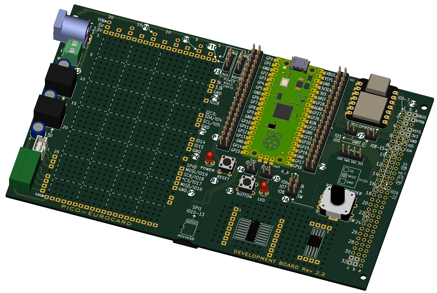
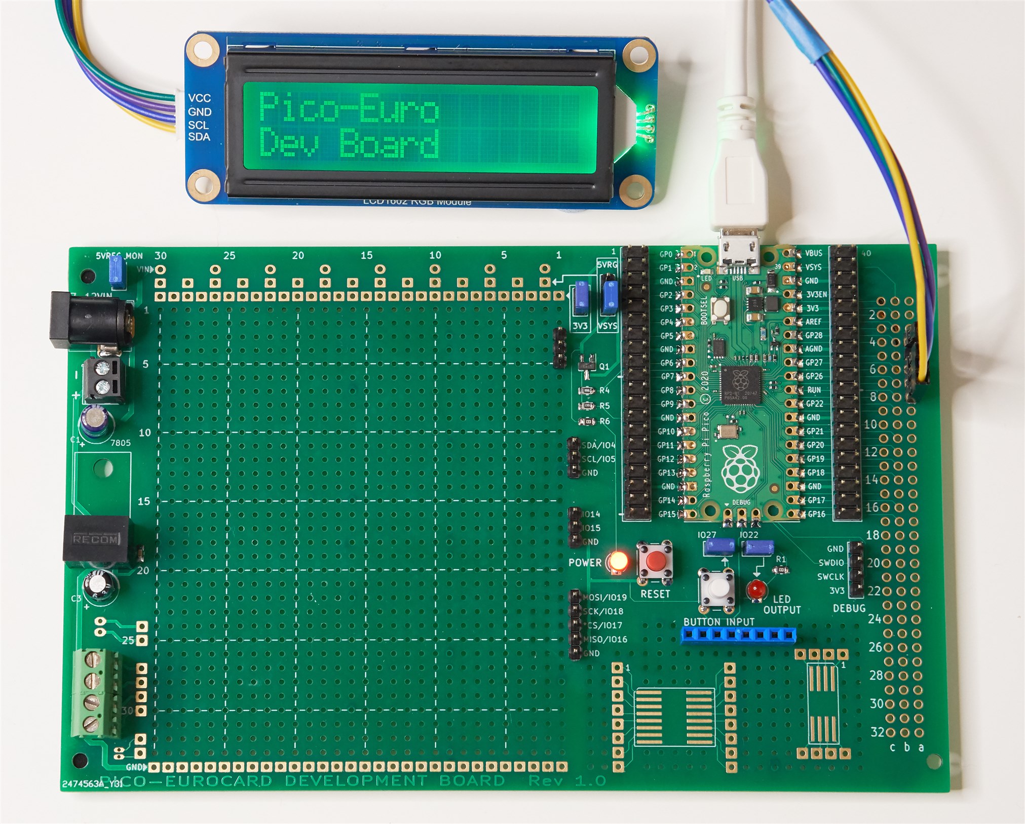
Photo of the earlier Rev 1.0 board:

image


What does it do?


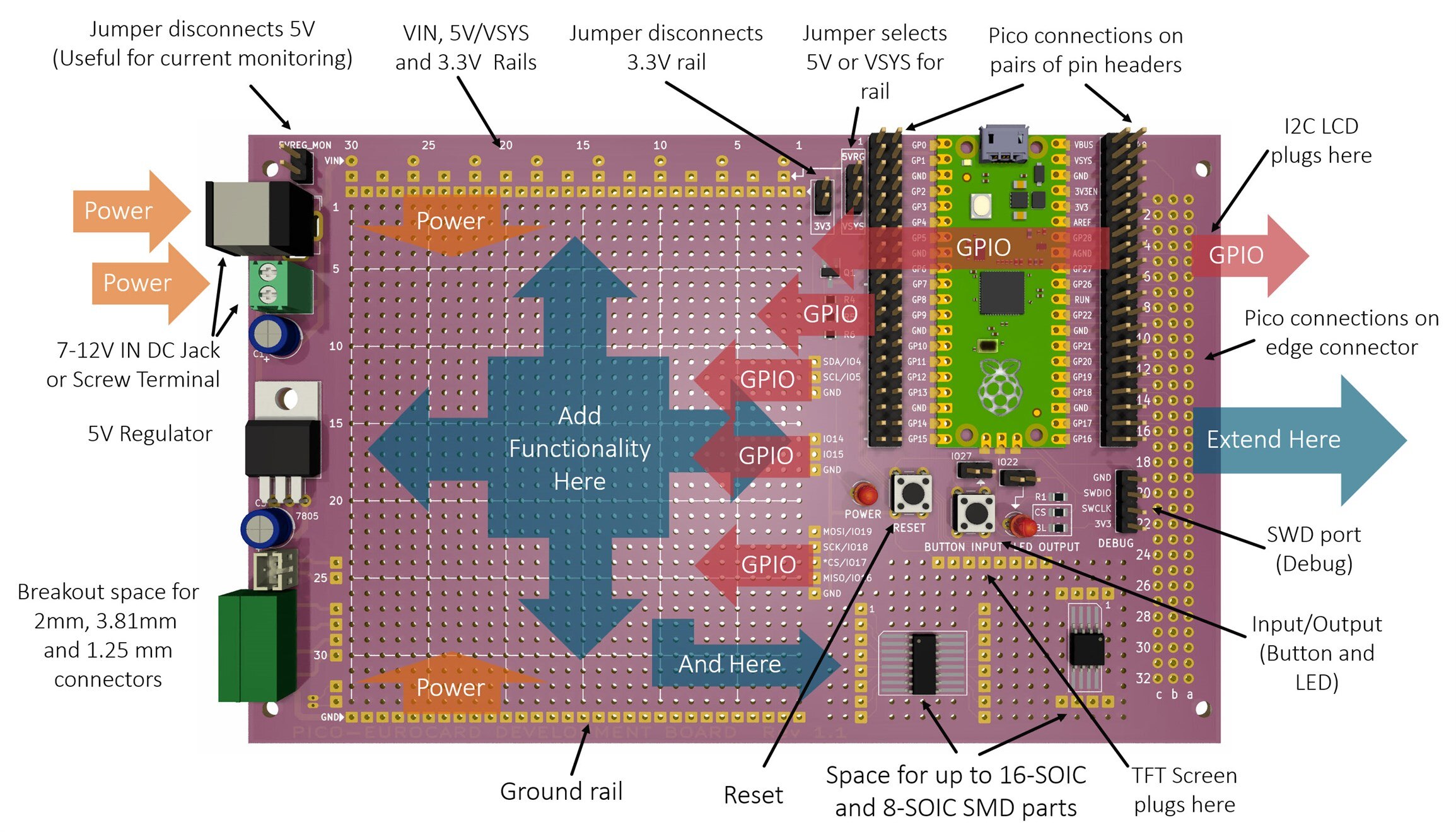
This project only does a fraction more than the bare minimum that could be needed to develop projects. There aren't any fancy features on the board; there's nothing to get in the way of the large prototyping area! The image here shows what the board contains.

image


This is the solder side of the board:

image

Building It

The board can be ordered from any PCB manufacturer like JLC PCB or Elecrow. It cost about $10 for five boards, not including postage.


The schematic and bill of materials are on GitHub (the board can be hand-soldered within about 20 minutes I expect). Not all connectors need to be purchased or soldered, since it really depends on how you wish to prototype. I intend to use very thin 30 AWG single-core wire to patch connections, instead of using jumper wires. I may replace the two DIL pin headers that flank the Pico, with two SIL pin headers instead, so that I can solder wires into the empty holes for attaching circuitry, and use the SIL pin headers for testing purposes (for instance attaching a logic analyzer with jumper wires).


Alternatively, the card edge connector pins can be used for attaching test equipment, since all the Pico GPIO pins are exposed there too.

Note: This is the Rev 1.x schematic. Scroll further below for Rev 2.x schematics!

image


Summary


An ultra-simple development board for the Pi Pico was presented. If it proves useful, I might create a second revision of it at some point (edit: there is now a revision 1.1 board on Github). I have yet to build the first revision 1.0 board (I have ordered some boards, and will post photos of it all in a week or two time when the boards arrive).


One thing I would like to improve on is providing space for a heatsink for the 7805 regulator (edit: revision 1.1 now has sufficient space to suit some typical TO-220 heatsinks). If the 7805 gets too hot with the revision 1.0 board, it can be swapped with a pin-compatible DC-DC converter replacement, such as MP-K78L05-1000R3 (on Rev 2.x boards, use these DC-DC converters instead: 5V: R-78E5.0-0.5 and 3.3V: R-78E3.3-0.5 , they will fit properly on the board).


Technically the board violates the Eurocard specification, so another improvement would be to rearrange things so that the Pi Pico is rotated by 90 degrees and brought to the left side so that the board can be slid into Eurocard enclosures. I currently can't see myself using this basic development board in such an enclosure, so for now I took the simpler option of not considering it. I might need a 4-layer board design for a compliant Eurocard because the current cheaper 2-layer design uses the edges of the board to route supply traces, which is no good for metal sliding rails in enclosures. So, all-in-all, for now, I didn't feel too bad that it violates Eurocard, with the benefit that it's a cheaper design as a result.


Thanks for reading!

Notes

See the comments section for improvements made for the Rev 1.1 board (files are at the pico-eurocard GitHub link along with the revision history). In particular, the Rev 1.1 board supports I2C LCD displays, and/or SPI TFT screens, which the earlier Rev 1.0 didn't.

Update: Board Revision 2.x

There is now a new revision 2.x board series. The main differences are:

* No TFT screen header pins. Some TFT screens were subtly different, and I was running out of space, so unfortunately if a TFT screen is needed, it will need to be patched to the appropriate connections manually. Another workaround is to use an I2C character display, there are pins for that on the large 3 x 32-way connector on the right of the board

* Slightly reduced perfboard area

* 5V and 3.3V DC-DC converters are now used instead of the 7805 and heatsink. This saves space, and provides two power supplies instead of one.

* MicroSD card support

* Built-in Picoprobe

* Built-in rotary encoder
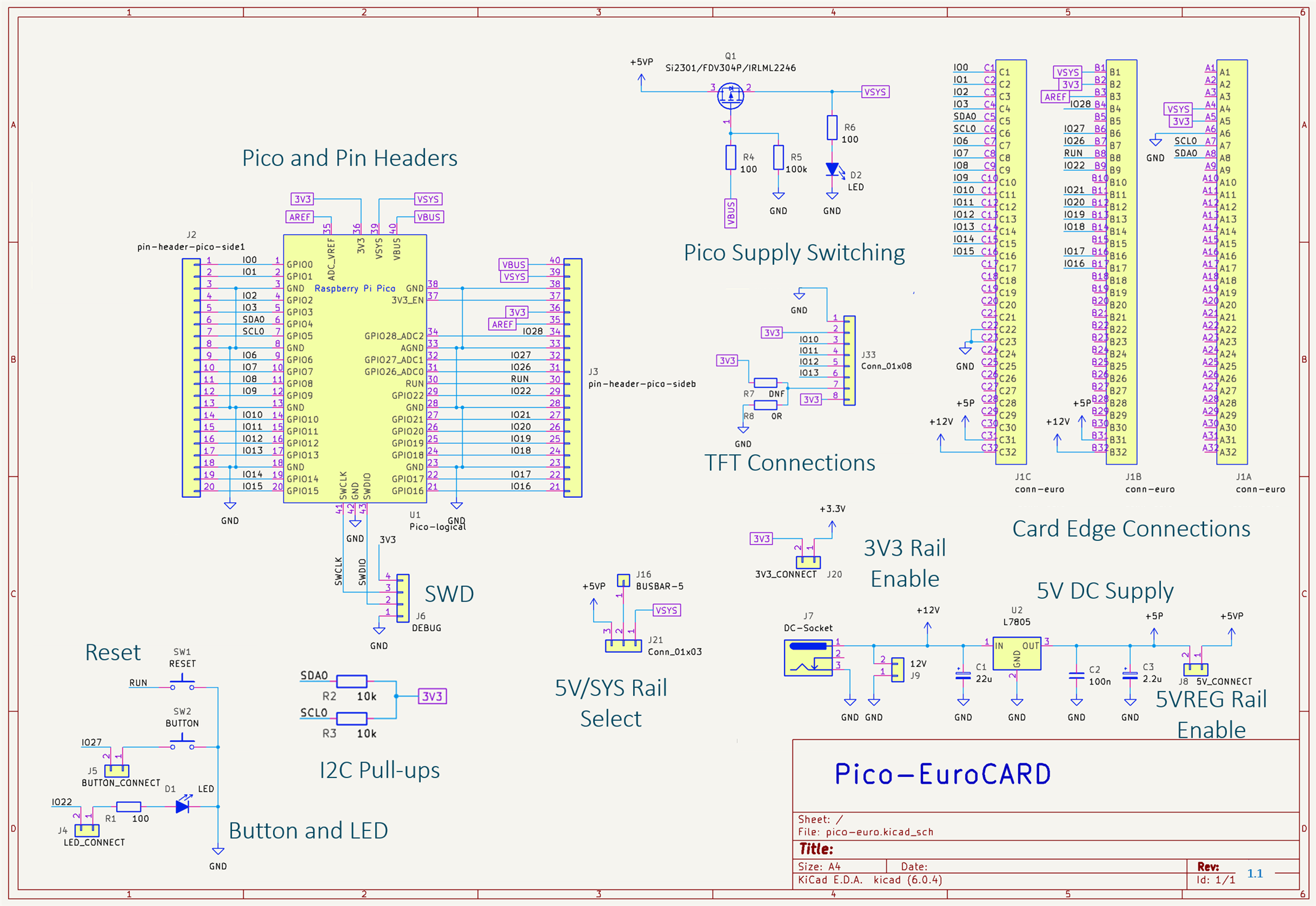
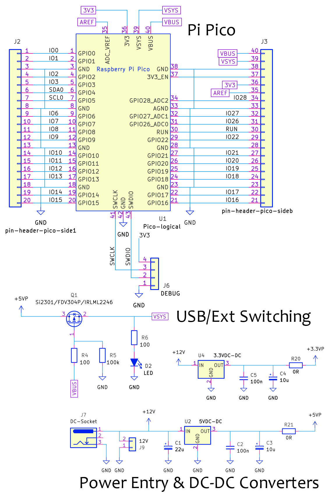
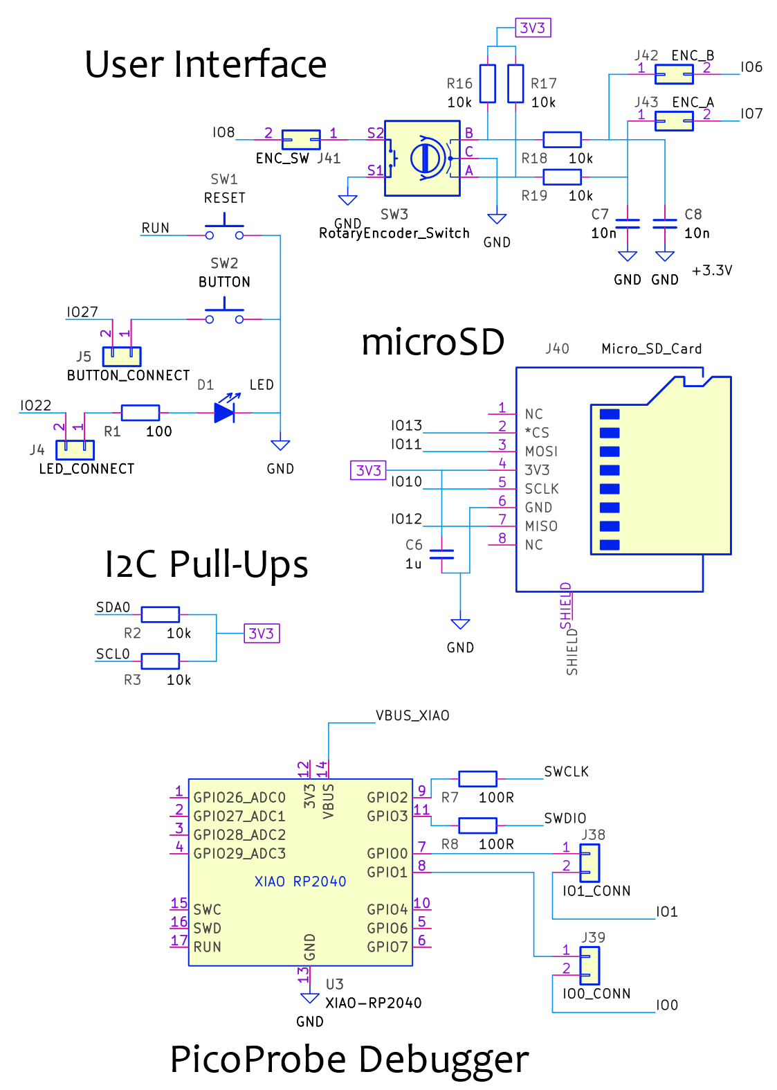
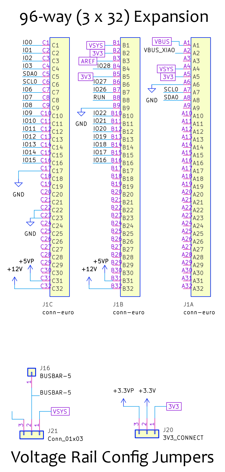
 

Rev 2.x Schematic

The 2.x board series has the following schematic (slight differences between 2.0, 2.1 and so on, but the component values and connections reflect all the dot-revisions, and anything significantly changed in any future dot-revision will be documented here). The component reference identifiers (such as J1, J2, and so on) have some differences compared to the silkscreen, but it is easy to identify which component is which. I reduced and simplified the silkscreen compared to the schematic, to get rid of the least-important bits of visual detail on the board.
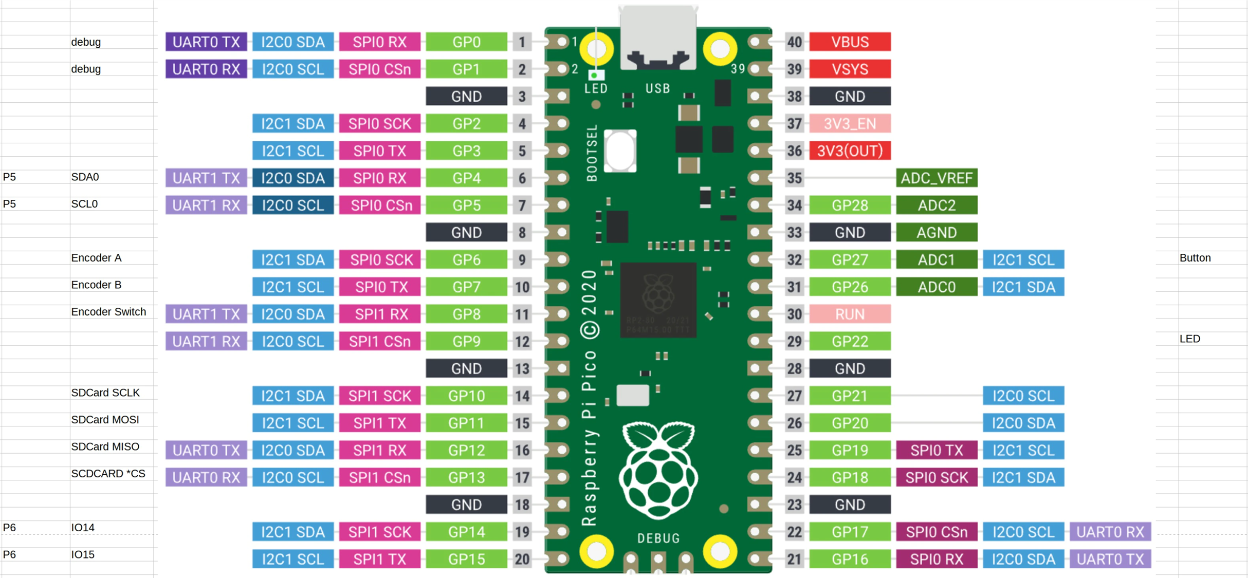
image

image

image

Pin Assignments

The default pin assignments on the board are shown in the diagram. The assignments can be removed or reassigned for most pins, by using shorting jumpers or jumper cables.

image

This diagram from Jan contains more detail:

image

  • Sign in to reply

Top Comments

  • The_Nick
    The_Nick over 2 years ago in reply to shabaz +1
    Hi Shabaz, I just saw your project featured on Youtube. Just looked at your github repository and thought lets change someting using KiCad. I cannot find a schematic and project file in the zip…
  • Jan Cumps
    Jan Cumps over 2 years ago +1
    a little addition that I find useful: the proto area has the right size to add one of those small breadboards . They come with double-sided tape. You can just stick one on. The white ones cost less than…
  • shabaz
    shabaz over 3 years ago in reply to Andrew J

    Hi Andrew,

    Thanks! Great ideas, I too was thinking along the same lines on some of your points. I was in two minds about the SOIC, and almost left it off for the reason you mention. Regarding the capability to add extra veroboard, there might be a possibility for that which could work with the current design, and another side-benefit is that a single development board could be reused multiple times, by swapping out the veroboard layer (although the development board is cheap anyway).

    It could be possible to take a 160x100 stripboard, cut it in half, and then solder SIL sockets (or SIL pins, if the development board has SIL sockets instead of pins) onto it as shown in the diagram below, which will support the board, and will also provide access to all the supply rails, I2C, SPI and a few extra pins, with no wiring required. The main problem is how to solder SIL connections onto the copper side of the stripboard, since that side will be facing down. It should be possible by raising the sockets slightly before soldering, which is ugly but workable, or alternatively to use surface-mount types:

    SIL Surface mount pins (example part code M20-8770342 ):

    image

    SIL surface mount sockets (example part code is BG125-03-A-1-1-0440-N-D ):

    image

    SIL pins (or sockets) needed (a couple more could be added for better support):

    image

    The veroboard height might clash with the 3V3 jumper at the top-right, I think it shouldn't clash, but if it does, a workaround is to have a right-angle pin header for that jumper.

    • Cancel
    • Vote Up 0 Vote Down
    • Sign in to reply
    • More
    • Cancel
  • scottiebabe
    scottiebabe over 3 years ago

    Really cute little protoboard! I have always wanted to try making my own perfboard. Perhaps I should try. I have wanted to experiment with placing a ground fill on the component to see if I could get the performance of prototyping on copperclad with the ease of perfboard. Ohh, and an ST7789 display too Slight smile Nice work!

    • Cancel
    • Vote Up 0 Vote Down
    • Sign in to reply
    • More
    • Cancel
  • shabaz
    shabaz over 3 years ago in reply to michaelkellett

    Hi Michael,

    Thanks!

    Ah great, good to know there are options regarding heatsink, even though space is tight.

    I just took a look, and also some U-shaped ones may fit, although had I left a couple of extra mm at the tab end, then a lot more would fit.

    For reference in case a heatsink ends up being needed:

    image

    This one, code 6237BG might be OK:

    image

    Or this one, with the capacitor raised a bit, and some tape on the edge of the heatsink : 

    image

    • Cancel
    • Vote Up 0 Vote Down
    • Sign in to reply
    • More
    • Cancel
  • Andrew J
    Andrew J over 3 years ago

    Excellent idea.  Personally, I wouldn’t be too worried about creating a Eurocard compliant version given the intended use for prototyping.  Is that something you would really encase?  Wouldn’t that happen after prototyping with a more fixed design on a specific PCB?  Maybe, I guess it would be an individual choice.  I rather suspect that as you use it you’ll find out what could be changed to make it even more flexible in any case.  My ideas for additional features might be:

    • connectors for off-board (heatsink) mounted components, e.g TO-220 regulators or MOSFETS.  I guess the question becomes how many of course!
    • mounts in the ‘functionality’ area to mezzanine things like vero board when more space is needed
    • Because DIL adapters are available, remove the 16-/8-SOIC footprints and use the space for something like a 2-line I2C LCD.
    • re-orient the regulator through 90 degrees so a bolt on wraparound heatsink could be attached

    it’s a cool design and I reckon it’s going to be really useful for PICO prototyping

    • Cancel
    • Vote Up 0 Vote Down
    • Sign in to reply
    • More
    • Cancel
  • michaelkellett
    michaelkellett over 3 years ago

    Nice project Shabaz.

    You could easily double the power handling of the 7805 by adding asimple L shaped aluminium heatsink.

    MK

    • Cancel
    • Vote Up 0 Vote Down
    • Sign in to reply
    • More
    • Cancel
<
element14 Community

element14 is the first online community specifically for engineers. Connect with your peers and get expert answers to your questions.

  • Members
  • Learn
  • Technologies
  • Challenges & Projects
  • Products
  • Store
  • About Us
  • Feedback & Support
  • FAQs
  • Terms of Use
  • Privacy Policy
  • Legal and Copyright Notices
  • Sitemap
  • Cookies

An Avnet Company © 2026 Premier Farnell Limited. All Rights Reserved.

Premier Farnell Ltd, registered in England and Wales (no 00876412), registered office: Farnell House, Forge Lane, Leeds LS12 2NE.

ICP 备案号 10220084.

Follow element14

  • X
  • Facebook
  • linkedin
  • YouTube