



In my blog Pico PID controller without floating point using DSP C++ fixed point API , I created a low footprint Pico PID example.
In this post, I reduce jitter by making sample clock steady, and let that drive the PID loop execution.
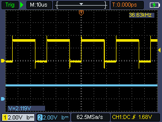
I used Google AI in this blog post to help explain jitter aspects, and help to set up ADC timer and trigger code.
All narrative is written by me, except where explicitly stated.
In a PID control loop, an inconsistent sample time can introduce jitter in the regulation. By letting a clock drive the exact ADC timing, the sample cadence becomes deterministic.
|
This content is AI generated by Google Gemini:
|

PID loop scheduling vs ADC sample scheduling: impact on firmware
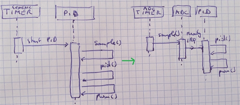
In the code of the previous post, a Pico timer generated an interrupt. That interrupt was the driver of executing a full PID loop:
- sample the output
- let PID calculate ideal PWM duty cycle, to have output match desired output
- set the PWM
In the deterministic sample design, there is no longer a clock that makes the PID tick.
The ADC clock ticks the sample time,
ADC ready interrupt pushes the regulation
- ADC clock initiates sample
- ADC raises interrupt when sample done
When the interrupt happens:
- let PID calculate ideal PWM duty cycle, to have output match desired output
- set the PWM (see end of this post: I replaced the PWM API call by a CPU-less DMA approach).
Real time startup behaviour, set to regulate output to 50%:
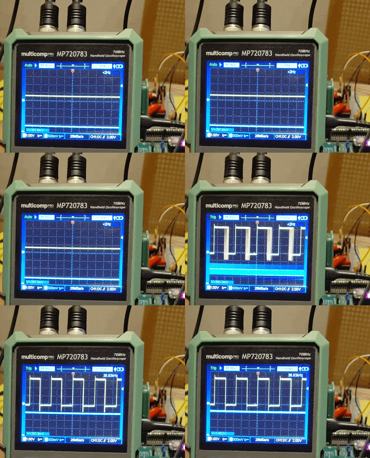
slomo 4X:
Source Code
#include "fixed_point.hpp"

#include "hardware/adc.h"
#include "hardware/gpio.h"
#include "hardware/pwm.h"
#include "hardware/irq.h"
#include "hardware/clocks.h"

import pid;

using namespace arm_cmsis_dsp;

using fp_t = Q15;
constexpr Q15 operator""_fp(long double val) {
        return operator""_q15(val);
}

using pid_controller_t = pid::pid<fp_t>;

// ADC and PWM declarations
// Pico SDK types are used here:
const uint ADC_PIN = 26;
const uint PWM_PIN = 0;
const uint PWM_CHANNEL = 0;

// frequency of PWM will be 125 MHz (on Pico1, 150 on Pico2) / (PWM_MAX * CKDIV)
// i.e. about 30.5 kHz for PWM_MAX = 4095
const uint PWM_MAX = 4095;
const float CKDIV = 1; // set CKDIV to 1 for approx 30.5 / 36.62 kHz PWM frequency if PWM_MAX is 4095
const uint32_t pwm_frequency = clock_get_hz(clk_sys) / (PWM_MAX * CKDIV);

const uint32_t adc_frequency = pwm_frequency / 10; // 3.663 kHze PID loop rate, 1/10 of PWM frequency
const float adc_clock_div = clock_get_hz(clk_adc) / adc_frequency;

// PID variables and objects
fp_t feedback;
constinit fp_t target_command = 0.66_fp; // Example target command in fixed point per-unit (0.0 to 1.0)
constinit fp_t output_pid = 0.0_fp; // Initialize output_pid to 0.0 in fixed point per-unit
pid_controller_t controller(0.1_fp, 0.01_fp, 0.05_fp); // Example PID gains for voltage control

// GPIO pin, to measure duration of a PID loop
const uint GPIO_PIN = 22; // happens to be the Pico Eurocard LED

void __not_in_flash_func(adc_pid_handler)() {
    gpio_xor_mask(1u << GPIO_PIN); // toggle
    feedback.v = static_cast<int16_t>((adc_fifo_get()) << 3); // Direct to 0.0 - 1.0 per-unit in Q15!

    output_pid = controller.compute(target_command, feedback);

    // Convert Q15 per-unit (0.0 to 1.0 excluded) to raw timer counts (0 to 65535)
    // the level will be 0 - 4095, 12 bits
    pwm_set_chan_level(slice_num, PWM_CHANNEL, static_cast<std::uint16_t>(output_pid.v >> 3)); // set PWM value
    gpio_xor_mask(1u << GPIO_PIN); // toggle
}

void init_adc() {
    adc_init();
    adc_gpio_init(ADC_PIN);
    adc_select_input(0);

    adc_fifo_setup(true, false, 1, false, false);
    adc_fifo_setup(true, false, 1, false, false);

    irq_set_exclusive_handler(ADC_IRQ_FIFO, adc_pid_handler);
    irq_set_enabled(ADC_IRQ_FIFO, true);
    adc_irq_set_enabled(true);

    adc_set_clkdiv(adc_clock_div);
}

void init_pwm() {
    gpio_set_function(PWM_PIN, GPIO_FUNC_PWM);
    slice_num = pwm_gpio_to_slice_num(PWM_PIN);
    pwm_set_clkdiv(slice_num, CKDIV);
    pwm_set_wrap(slice_num, PWM_MAX-1);
    pwm_set_chan_level(slice_num, PWM_CHANNEL, 0);
    pwm_set_enabled(slice_num, true);
}

void init_gpio() {
    gpio_init(GPIO_PIN);
    gpio_put(GPIO_PIN, 0);
    gpio_set_dir(GPIO_PIN, true);
}

int main() {
    init_gpio();
    init_pwm();
    init_adc();

    adc_run(true);

    while (true) {
        tight_loop_contents();
    }
}
CMake script
cmake_minimum_required(VERSION 3.28)

set(CMAKE_C_STANDARD 11)
set(CMAKE_CXX_STANDARD 26)
set(CMAKE_EXPORT_COMPILE_COMMANDS ON)
set(CMAKE_CXX_FLAGS "${CMAKE_CXX_FLAGS} -fmodules-ts -fcommon -fno-rtti -fno-exceptions")
set(CMAKE_CXX_FLAGS "${CMAKE_CXX_FLAGS} -mthumb -mfpu=fpv5-sp-d16")
set(CMAKE_CXX_STANDARD_REQUIRED ON)

message("CMAKE_BUILD_TYPE is set to '${CMAKE_BUILD_TYPE}'")
string(TOUPPER "${CMAKE_BUILD_TYPE}" uppercase_CMAKE_BUILD_TYPE)
if(uppercase_CMAKE_BUILD_TYPE STREQUAL "DEBUG")
    set(PICO_DEOPTIMIZED_DEBUG 1)
    message(STATUS "Debug configuration detected. Switch PICO_DEOPTIMIZED_DEBUG on.")
else()
    set(PICO_DEOPTIMIZED_DEBUG 0)
    message(STATUS "Debug configuration not detected. Swith PICO_DEOPTIMIZED_DEBUG off.")
endif()
message(STATUS "PICO_DEOPTIMIZED_DEBUG is set to '${PICO_DEOPTIMIZED_DEBUG}'")

# This block automatically detects the active selection in VS Code
if(CMAKE_CXX_COMPILER_ID STREQUAL "GNU" OR CMAKE_CXX_COMPILER_ID STREQUAL "Clang")

    # 1. If you select "Debug" in VS Code:
    set(CMAKE_CXX_FLAGS_DEBUG "-O0 -g -gstrict-dwarf -gdwarf-3" CACHE STRING "Debug flags" FORCE)

    # 2. If you select "Release" in VS Code:
    set(CMAKE_CXX_FLAGS_RELEASE "-O3" CACHE STRING "Release flags" FORCE)

endif()

add_compile_options(-march=armv8-m.main+fp+dsp)


# path to PICO utilities (if needed)
if (NOT DEFINED ENV{PIOASM_DIR})
        message("PIOASM: set PIOASM_DIR env variable if you use PIO")
else()
        message("PIOASM: PIOASM_DIR env variable is set to '$ENV{PIOASM_DIR}'")
        set(pioasm_DIR $ENV{PIOASM_DIR})
endif()
if (NOT DEFINED ENV{PICOTOOL_DIR})
        message("PICOTOOL: set PICOTOOL_DIR env variable if you create uf2 output with pico_add_extra_outputs()")
else()
        message("PICOTOOL: PICOTOOL_DIR env variable is set to '$ENV{PICOTOOL_DIR}'")
        set(picotool_DIR $ENV{PICOTOOL_DIR})
endif()

# set(PICO_PLATFORM rp2350-riscv CACHE STRING "Pico Platform")
set(PICO_PLATFORM rp2350-arm-s CACHE STRING "Pico Platform")
set(PICO_BOARD pico2 CACHE STRING "Board type")


include(pico_sdk_import.cmake)

project(pico_pid_template C CXX ASM)

pico_sdk_init()

include(FetchContent)

# CMSIS DSP fixed point c++ library dsppp
FetchContent_Declare(dsp_fixed_point
  GIT_REPOSITORY "https://github.com/ARM-software/CMSIS-DSP.git"
  GIT_TAG HEAD
  GIT_SHALLOW OFF # needed to find the commit HEAD
  # prevent makefile execution (if any)
  SOURCE_SUBDIR =
)
FetchContent_MakeAvailable(dsp_fixed_point)

# PID embedded C++ library
FetchContent_Declare(pid_embedded
  GIT_REPOSITORY "https://github.com/jancumps/pid_embedded_cpp.git"
  GIT_TAG origin/main
  # prevent makefile execution (if any)
  SOURCE_SUBDIR =
)
FetchContent_MakeAvailable(pid_embedded)

include_directories( # this project uses CMSIS DSP fixed point library, so include the path to the CMSIS DSP headers
    ${PICO_SDK_PATH}/src/rp2_common/cmsis/stub/CMSIS/Core/Include
    ${dsp_fixed_point_SOURCE_DIR}/dsppp/Include/dsppp
)


add_executable(${CMAKE_PROJECT_NAME})

target_compile_definitions(${CMAKE_PROJECT_NAME} PRIVATE
    ARM_MATH_CM33=1
)

target_sources(${CMAKE_PROJECT_NAME}
        PUBLIC
        ${CMAKE_CURRENT_SOURCE_DIR}/main.cpp
)
target_sources(${CMAKE_PROJECT_NAME}
        PUBLIC
        FILE_SET cxx_modules TYPE CXX_MODULES FILES
        ${pid_embedded_SOURCE_DIR}/source/pid_template.cpp
)

target_link_libraries( ${CMAKE_PROJECT_NAME}
        pico_stdlib
        hardware_adc
        hardware_gpio
        hardware_pwm
)

pico_add_extra_outputs(${CMAKE_PROJECT_NAME} )
CMake edits to make it build for Pico RP2040:
# set(CMAKE_CXX_FLAGS "${CMAKE_CXX_FLAGS} -mfpu=fpv5-sp-d16") # TODO: enable for Pico2# add_compile_options(-march=armv8-m.main+fp+dsp) # TODO: enable for Pico2add_compile_options(-march=armv6-m)# set(PICO_PLATFORM rp2350-arm-s CACHE STRING "Pico Platform") # TODO: enable for Pico2# set(PICO_BOARD pico2 CACHE STRING "Board type") # TODO: enable for Pico2set(PICO_PLATFORM rp2040 CACHE STRING "Pico Platform")set(PICO_BOARD pico CACHE STRING "Board type") # ARM_MATH_CM33=1 # TODO: enable for Pico2 ARM_MATH_CM0PLUSTimings
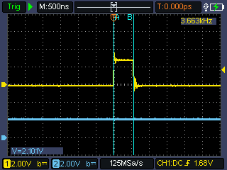
Single execution: The PID loop lasts 560 ns with full optimisation on.
|
After I wrote this bog, I optimised the loop further, using DMA. Instead of setting the PWM duty cycle right after the PID loop, I wrote the requested duty cycle to a variable, and flagged DMA that it needs to do its job. For the CPU, this flagging is cheaper than setting the duty cycle directly via an SDL call. The result is that the PID loop now takes 460 ns instead of 560 ns, on a Pico 2 / RP2350 ARM at 150 MHz.
code snippet:
|
The samples happen clock steady every 276 µs.
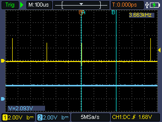
Measurements done on a Pico 2 / RP2350 ARM, at the default 150 MHz.
I used a GPIO pin to measure both times, toggled in the ADC interrupt handler.
It's not an exact representation of when the sample happens, and when the PID is finished. But I think this is a reasonable way to validate timings.
references:
Development kit: Pi Pico Eurocard Development Board
Previous Pico PID blog: Pico PID controller without floating point using DSP C++ fixed point API
PID class GitHub repository
VS Code project - with DMA. Configured for Pico 2 / RP3250 ARM. Check the CMake section above to configure for an RP2040. The non-dma source is available as main.cpp.pidtimer: pico_pid_template_dma_20261024 (2).zip
VS Code project - with DMA. Configured for Pico 2 / RP3250 RISC pico_pid_template_20261025_riscv.zip.
Thank you for reading
