


Note: This is a continuation of an earlier post, Raspberry Pi 3 Cooling / Heat Sink Ideas
Introduction
Having recently been experimenting with Pi 3’s and displays, analog-to-digital converters (ADCs) and a very high speed data logging multimeter from Keysightvery high speed data logging multimeter from Keysight, the stars aligned to allow me to measure several parameters to get to know the Pi 3 a bit better.
As the Pi’s System-on-Chip (SoC) which contains the CPU and cache memory works harder, the SoC will consume more power and get hotter. It would be expected to see current consumption rise (since Power = Voltage x Current) and it would be expected to see the temperature rise as it gives off heat.
To help dissipate the heat to the environment quicker, a heat sink can be used. To calculate what size heat sink is needed requires a lot of information; the semiconductor devices etched in the silicon die can only tolerate a certain temperature (perhaps 150 degrees C) and there is a thermal resistance between the silicon and the outside world, through the SoC casing. This means that heat will not be able to escape rapidly through the SoC, causing the temperature to rise. Similarly when a heat sink is glued onto the SoC, the adhesive has a thermal resistance too. The heat sink too has a thermal resistance to the environment (air) and there may be an air flow (passive, or active using a fan) or poor air flow (a full enclosure around the Pi).
In the absence of technical information (the characteristics of the silicon die used in the SoC are unknown, as are details about the SoC enclosure and precisely how much power the SoC dissipates) it was decided to conduct a few measurements. It is possible to measure the current the entire Pi consumes, but difficult to measure how much of that is due to the SoC, since there are other parts on the Pi 3’s printed circuit board (PCB). With no circuit diagram or board layout diagrams it would be difficult to solve this problem.
Any test results are for general guidance only the values can change from release to release and I deliberately picked the 26 Feb 2016 Raspbian release since I know that the throttling behaviour is more aggressive in the subsequent release I was more interested in trying out the Keysight U1282AU1282A multimeter in a test bed for some custom measurement circuitry and software the Pi 3 happened to be an interesting thing to try it on
What is ‘Throttling’?
To deploy and use a Pi there are many things to consider such as heat sink selection, how it is connected to the SoC, air flow, and enclosure design. All this is needed to ensure the Pi (or any device) runs as expected and reliably. Things can be done to ensure fault conditions do not cause harm. One example would be to have two fans; if one fails the other can take over.
In terms of software if necessary the Pi can take control and reduce clock speeds (this is known as dynamic frequency scaling or ‘throttling’) if the temperature measured inside the SoC hits any thresholds. The exact algorithm is outside user control to an extent; it depends on the particular software release and raspberrypi.org decisions. In general throttling is very drastic and intrusive; if applications cause throttling then either a different application should be used (or it should be immediately rewritten) or a different processor must be used. Why is this?
The reason is, for a home PC or laptop or a mobile phone there is not really an issue if the processor changes speed; applications may run slower but they still run.
For a single board computer, this is unacceptable because it may be interfaced to the outside world through sensors and output devices such as relays and motors. A change in behaviour could have real, physical consequences. This is not just theoretical. The first moon landing saw the guidance computer being overwhelmed with a high level of events (known as a 1202 alarm). This is no different to a situation where the input data rate is unchanged but the processor speed has dropped underneath the software’s feet. A more likely scenario today could be a computer in control of a machine where a collision could be disastrous to the machine and anyone nearby.
At first thought a possible solution could be to just pick-and-choose your battles, i.e. choose different use-cases and scenarios where you can develop software intended for slow sensor and actuation rates. That way, even if clock speeds halve, there may be no issue if the sensor measurement or output is delayed by a second or two, because it will be safe for those use-cases. However, a massive warning flag is that even if input/output can be comfortably delayed by a second or so, there still is no guarantee that all is well because when software is tested for single board computers, it is done using particular hardware. Rightly or wrongly there is an expectation that the underlying hardware (and its speed) will not change. When changes occur, modern software can behave unexpectedly. Most software is written with multiple areas of code (known as processes) which execute asynchronously to each other, and only occasionally synchronise up at pre-defined parts of the code (the synchronisation procedure is known as inter-process communication). If synchronisation is unexpectedly delayed or badly implemented then unexpected behaviour and software crashes can be extremely likely. It is known as a race condition.
It is quite easy to write a program which will happily run correctly 100% of the time at a particular clock speed, but which degrades and/or crashes as the clock speed is altered. If the developers and testers never anticipate nor actually run tests at different processor speeds they could never spot the issue even if they tested for a year, yet it would be reproducible within seconds if the clock speed was changed.
Incidentally, this is why for critical systems you must not run additional unrelated software on the same hardware without significant assessment, testing and guarantees from the software creators; better to use two (or more) separate computers. One piece of software could cause the other to crash. If you’re curious to try some experiments, I wrote a short piece of software called do1010 that runs perfectly fine at 1.2GHz (for example if you set force_turbo=1 and core_freq=400 in /boot/config.txt file on the Pi), but will have interesting effects as the clock speed reduces (e.g. by running a software tool to heavily stress the SoC causing throttling to occur) and will crash at a sufficiently slow speed. At 1.2GHz it just slowly displays toggling 1 and 0 in sequence (i.e. 1010101010…) about once per second and will do so forever if the hardware (i.e. clock speed in this case) doesn't change. At slower speeds it misbehaves very quickly.

If instead of a 1 or a 0 it had been turning on and off a heater for (say) temperature regulation for a farm animal environment, you can imagine the disaster if it crashed in the off or on position and didn't restart.
Test Bed Topology
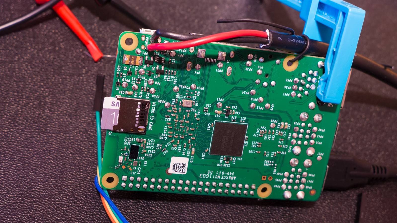
A Pi 3 was used that had previously been connected to a heat sink and thermistor.

There is more information on that here, but in summary a ceramic heat sinkceramic heat sink was used (Note: I used a different ceramic heat sink but it is out of stock; the one linked here is a suitable replacement) because it has far lower thermal resistance (10.1 degrees C per Watt) compared to the traditional little stick-on aluminium heat sinks like this Raspberry Pi Heat Sink Kit that has a 25 degrees C per Watt thermal resistance value.
The ceramic heat sink achieves the excellent low thermal resistance because it has a micro-pores that can dissipate heat extremely well.
The thermistor used was Betatherm 100K6A1BBetatherm 100K6A1B and it was small enough to be able to be pushed into a hole that could be drilled in the heat sink.
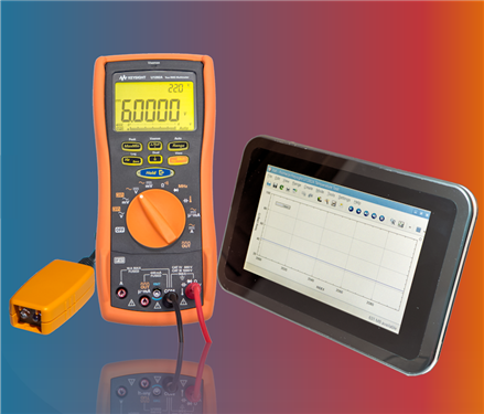
A Keysight U1282A multimeterKeysight U1282A multimeter was used to capture the thermistor resistance measurements. It is very fast (10 captures per second) so that even subtle short changes in temperature can be easily detected. In fact the combination is sensitive enough to detect the heat given off by a laser pointer beam (which is less than 1mW).
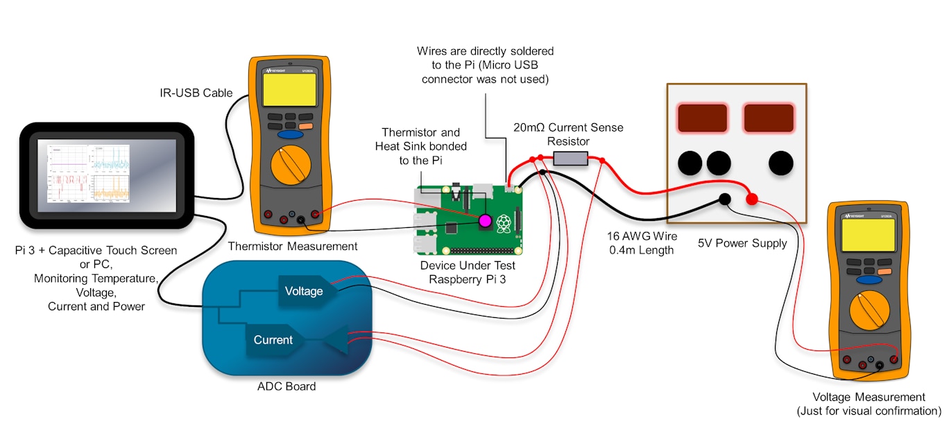
To get power into the Pi 3, the official power supply was not used; instead a 4A capable bench supply was used with short thick wires. The wires were 16 AWG in size (1.29mm diameter) compared to the 18 AWG (1.02mm diameter) wires in the official 2.5A power supplyofficial 2.5A power supply. The wires were directly soldered to the underside of the Pi (to the test pads marked PP2 and PP5 for +5V and 0V respectively). It was tricky – 16 AWG wire is fat! To avoid ripping of the pads, the wire needed to be tied in place for a bit of strain relief.
Some known resistance is needed to ‘sense’ the current through the wire (and hence the current through the Pi). A 20 milliohm resistance was used for that purpose (you don't need it to be anything near as large as the one in the photo but it was all I had at hand; a 0.5W resistor will be sufficient). Incidentally the other connectors on the board are not relevant, they are for unrelated experiments).
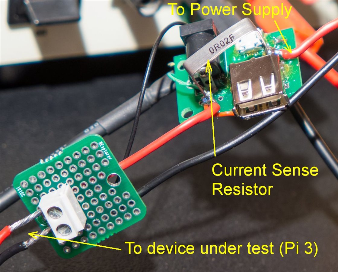
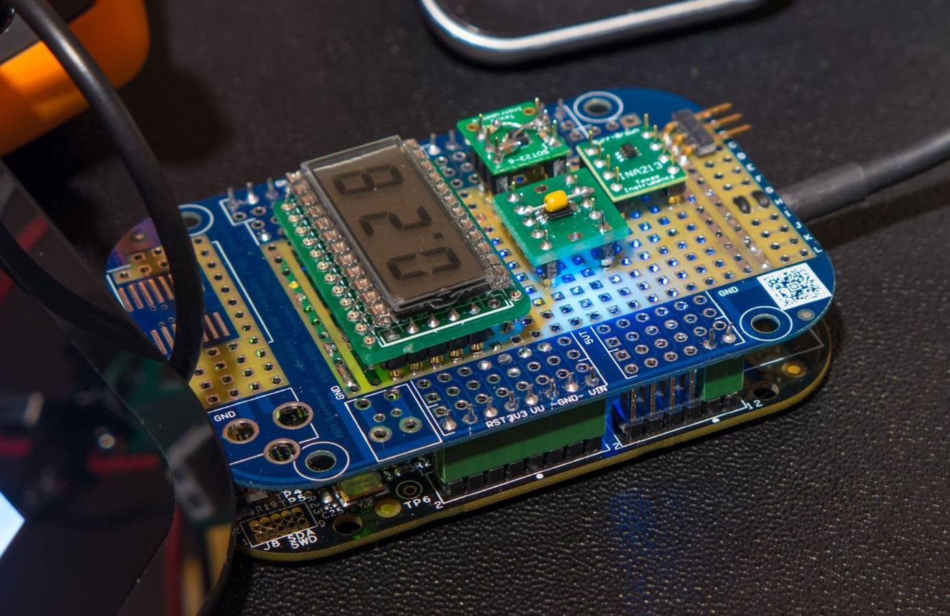
The voltage across the resistance is proportional to the current going through the Pi (Ohm's law). The voltage can be measured with a multimeter or by using an analog-to-digital converter. (ADC). An ADC was used because I don’t have many logging multimeters. The accuracy of the ADC was determined before-hand with some known resistances and a handheld multimeter. The ADC reading is accurate to within a few milliamps (the software can self-calibrate to remove any offset, and gain error was removed through calibration by using a known load and confirming with a multimeter). If there is interest, let me know in the comments and I will write up the ADC project. It was designed to provide an accurate way to measure the power that USB devices consume dynamically.
The data from the U1282AU1282A multimeter and the ADCs is collected up and graphically displayed using the kst’ application. It was actually possible to do all this using another Pi (and a 7 inch touch screen) so that it could be conveniently monitored for extended periods. But for the purposes of obtaining screen shots for this write-up, the software was run on a normal PC.
Running Tests
Not a lot of testing was done; the Pi was powered up and measurements taken with the Pi doing nothing (just running Raspbian with nothing connected up). A few stress tests were run (in particular a Sysbench command that computes prime numbers and a stress command that makes all four cores work continuously, and a cpuburn-a53 program which exercises ARM NEON functionality (ARM NEON is hardware inside the SoC that is used by software libraries for accelerating math functions). I also tried using omxplayer to use the graphical processor unit (GPU) slightly.
For each of these tests the temperature, voltage and current were monitored in real time (and the power was computed in real time using Power = Voltage x Current). All tests used the Pi with the ceramic heat sink attached and no enclosure. Ambient temperature was around the 25 degree C ballpark and was uncontrolled.
After these tests were run, a small fan (25x25mm) was positioned a few centimetres away from the heat sink and run at full speed. It ran at 5V and consumed about 80mA. With the fan running, a couple of tests were repeated.
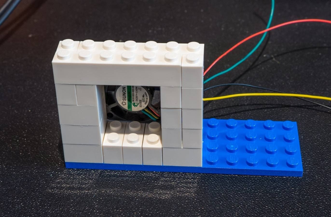
The fan was just positioned using some Blu-tack (putty) holding it against a Lego aperture that acted like a short air duct.
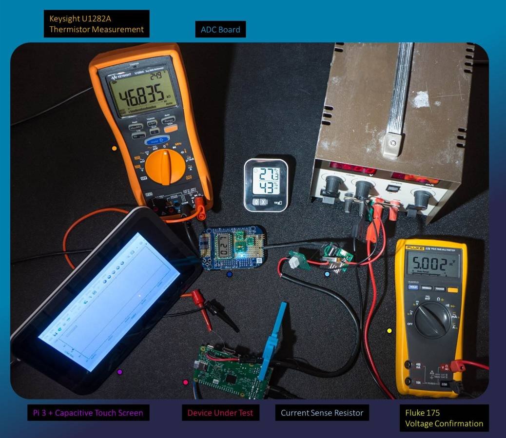
To run the tests I had to get my desktop/dashboard looking organized slightly! Dynamically updating charts are on the left, the Pi console is at the bottom (SoC reported temperature is in the blue window at the bottom) and the remainder was used to show the live action or any screenshots and the topology and any commands I would need to paste into the console. At top-left any observations/conclusions are displayed in a blue box.
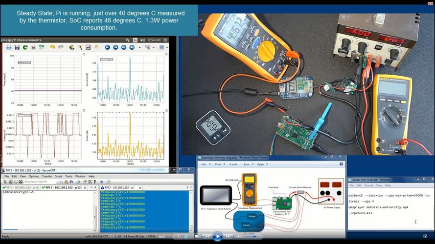
For the detailed results there is a 30-minute video recording (right-click to open in a window to allow full-screen) which was done in one take to make sure no subtle data was lost, with no pauses except for a 5 minute period which is marked in the video during which time I was waiting for the temperature to drop after a test, and another break during which time I added the fan.
If you don't want to sit through a 30-minute video here is the exec summary:
Results
For all these tests, as mentioned there was nothing connected to the Pi.
If a Logitech Unifying USB device is attached then that requires an additional 30mA to be added to the figures.
If there is a USB memory stick plugged in doing nothing then a further 30mA should be added.
Here are the results with just the heat sink and no fan:
| Scenario # | Description | Current | Temperature reported by SoC | Temperature measured by Thermistor |
|---|---|---|---|---|
| 1 | Pi doing nothing. Rasbian running. | 266mA | 46°C | 41°C |
| 2 | Pi running omxplayer, playing a file on the Micro SD card (connecting or disconnecting the HDMI plug made no difference) | 285mA | ||
| 3 | Calculate Primes using sysbench | 365mA | ||
| 4 | Running stress --cpu 4 | 670mA | 75°C | 67°C |
| 5 | Running cpuburn-a53 | 1.45A | 85°C | 75°C |
It can be observed that the temperature was very high for the last couple of tests; hot enough to literally fry an egg. This was with a good heat sink (10 degrees C per Watt thermal resistance) nevertheless throttling was observed during test #5. The throttling effects are in the video and that part is worth observing.
In the shut-down state (type sudo poweroff at the command line) the Pi still consumes 80mA.
After this, the fan was applied and a couple of tests re-run as mentioned (results are in the video). It improved the situation despite being such a tiny fan.
Summary

In summary, although it was obvious, the results do corroborate initial thoughts that a heat sink is useful to allow the Pi to run at a high speed with less risk of throttling (but it does not necessarily rule out throttling as shown by the results). The ceramic heat sink is strongly advised not only because of the low thermal resistance but because it is not electrically conductive and therefore there is no risk of electrical shorts and there is a greatly reduced risk of impacting 802.11 (WiFi) and Bluetooth performance (the antenna is less than 20mm away from the SoC). An aluminium heat sink near the antenna would definitely impact antenna performance.
If ambient temperature is expected to be high (for example if the Pi is totally enclosed) then throttling is more likely to occur for heavy processing loads.
Inside an enclosure active cooling should be considered unless sufficient provisions can be made for passive air flow (such as using a heat pipe to the outside world). As shown in the tests, even without an enclosure throttling can occur if there is no fan. This was at 25 degrees C ambient temperature and would be worse in warmer environments.
If a fan is used, the 25x25mm one was effective (you can see the reduction in throttling in the video) but it didn’t eliminate throttling entirely for the last scenario although the effect was greatly diminished. The last scenario could be considered by some to be extreme though. It really depends on how the Pi is deployed.
Top Comments