|
The Pico has a set of PIO co-processors. They are real-time controllers that can execute logic with deterministic timing. Ideal to run strict-timed sequences and state machines. And to implement extra peripherals.
|
Follow up of Stepper Motor Control with Raspberry Pico PIO and DRV8711 driver- Part 1: Hardware Provisioning
SPI requirements and setup
The TI DRV8711 stepper motor driver, that we use in this project, relies on pre-configuration via SPI.
These are the Pico resources I reserve:
| signal | DRV8711 | Pico |
| SPI CLK | SCLK | default SCLK IO18 |
| SPI CS | SCS | default CS* IO17 |
| SPI MISO | sdato | default MISO** IO16 |
| SPI MOSI | sdati | default MOSI IO19 |
| SPI | default spi0 |
SPI settings:
| baud | 1000 * 1000 |
| message size | 16 bits |
* DRV8711 uses a chip select that's active high. Pico's SPI library doesn't support that, so I will bit bang that pin.
** DRV8711 uses open collector for outputs. Pico will have to provide the rail via a pull-up.
The setup code isn't complex. You 'll recognise the special cases mentioned below:
void init_drv8711_spi_hw() {
    // Enable SPI 0 at 1 MHz and connect to GPIOs
    spi_init(spi_default, 1000 * 1000);
    spi_set_format(spi_default, 16, SPI_CPOL_0, SPI_CPHA_0, SPI_MSB_FIRST); // 16 bit registers
    gpio_set_function(PICO_DEFAULT_SPI_RX_PIN, GPIO_FUNC_SPI);
    gpio_set_pulls(PICO_DEFAULT_SPI_RX_PIN, true, false); // drv8711 outputs are open drain
    gpio_set_function(PICO_DEFAULT_SPI_SCK_PIN, GPIO_FUNC_SPI);
    gpio_set_function(PICO_DEFAULT_SPI_TX_PIN, GPIO_FUNC_SPI);
    // CS is active-high, invert pin action
    gpio_set_function(cs_, GPIO_FUNC_SPI);
    gpio_set_outover(cs_,GPIO_OVERRIDE_INVERT );
}
I provided a helper for bit write (the width of the DRV8711 registers):
static void spi_write(const uint16_t &data) {
    spi_write16_blocking(spi_default, &data, 1);
}
Here's an example of a register structure, with a convert-to-16-bit operator. This code sits in a DRV8711 driver that I wrote for this project.
struct CTRL {
                            // address 14-12
    unsigned int dtime;		// 11-10
    unsigned int isgain;	// 9-8
    unsigned int exstall;	// 7
    unsigned int mode;		// 6-3
    unsigned int rstep;		// 2
    unsigned int rdir;		// 1
    unsigned int enbl;		// 0
    inline operator uint16_t() const {
        return (0x0000 << 12) | (dtime << 10) | (isgain << 8) |(exstall << 7) | (mode << 3) | (rstep << 2) | (rdir << 1) | (enbl);
    }
};
Then the declaration of an object of that type, with initialisation. This allows the linker / loader to fill this structure straight away at firmware loading. Not a single clock tick of runtime code is involved in this construct:
drv8711::CTRL reg_CTRL {
    0x0003, // DTIME
    0x0003, // ISGAIN
    0x0000, // EXSTALL
    0x0003, // MODE 8 microsteps
    0x0000, // RSTEP
    0x0000, // RDIR
    0x0001  // ENBL
};
I have that mechanism for all DRV8711 registers. Here's the code to actually write the setup to the IC:
void init_drv8711_settings() {
    // Set Default Register Settings
    spi_write(reg_CTRL);
    spi_write(reg_TORQUE);
    spi_write(reg_OFF);
    spi_write(reg_BLANK);
    spi_write(reg_DECAY);
    spi_write(reg_STALL);
    spi_write(reg_DRIVE);
    spi_write(reg_STATUS);
}
The full code will be attached when I'm a bit further into this project. Next post will focus on provisioning the non-SPI pins.
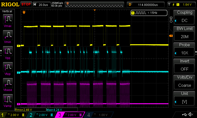
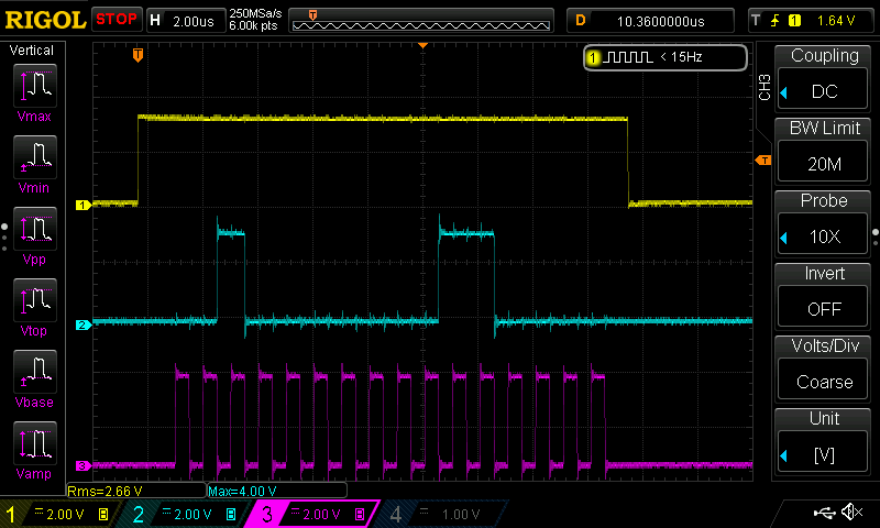
Meanwhile: here's the full conversation from Pico to DRV8711: