


|
The Pico has a set of PIO co-processors. They are real-time controllers that can execute logic with deterministic timing. Ideal to run strict-timed sequences and state machines. And to implement extra peripherals.
|
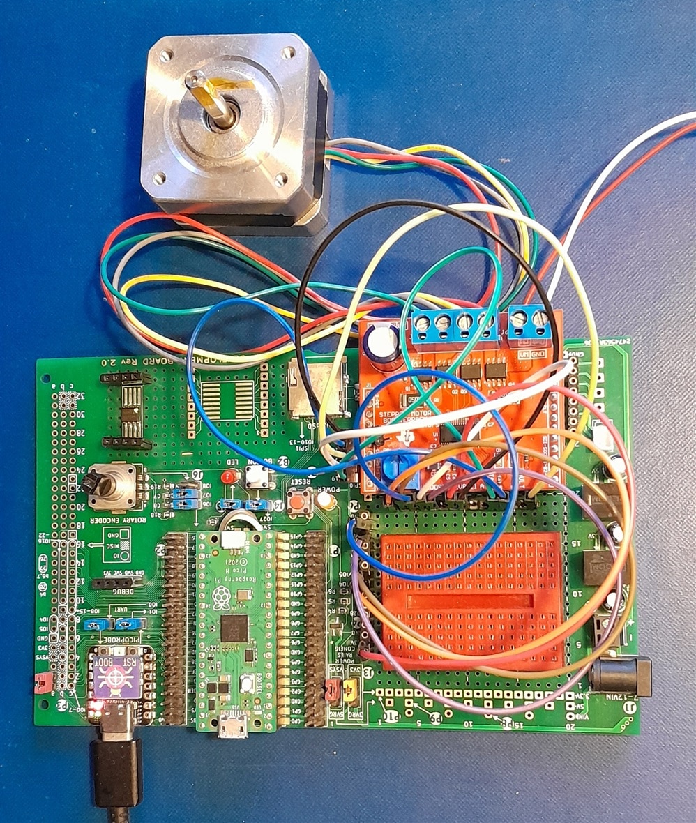
Follow up of Stepper Motor Control with Raspberry Pico PIO and DRV8711 driver- Part 2: SPI .
Next to power, the driver IC has some digital inputs that we need to entertain. This post is my doco on how I connected them. Very short, nothing real happening here.
These are the Pico resources I reserve:
| signal | DRV8711 | Pico |
| direction | DIR |
IO4 |
| step | STEP |
IO5 |
| sleep | SLEEP |
IO14 |
| reset | nRESET |
IO15 |
| power |
3V3 |
|
| ground |
GND |
All are outputs, Here's the code to set them. And a little helper.
#define NSTALL (-1)
#define NFAULT (-1)
#define NSLEEP (14)
#define RESET (15)
#define DIR (4)
#define STEP (5)

// ...

void init_drv8711_hw() {
    // nStall and nFault as input
    // not used
    // gpio_init(NSTALL);
    // gpio_set_dir(NSTALL, GPIO_IN);
    // gpio_set_pulls(NSTALL, true, false); // drv8711 outputs are open drain
    // gpio_init(NFAULT);
    // gpio_set_dir(NFAULT, GPIO_IN);
    // gpio_set_pulls(NFAULT, true, false); // drv8711 outputs are open drain

    // nSleep and Reset as output
    gpio_init(NSLEEP);
    gpio_put(NSLEEP, 0);
    gpio_set_dir(NSLEEP, GPIO_OUT);
    gpio_init(RESET);
    gpio_put(RESET, 0);
    gpio_set_dir(RESET, GPIO_OUT);

    // bin1 and bin2 as output
    // not used

    // DIR and STEP as output
    gpio_init(DIR);
    gpio_put(DIR, 0);
    gpio_set_dir(DIR, GPIO_OUT);
    gpio_init(STEP);
    gpio_put(STEP, 0);
    gpio_set_dir(STEP, GPIO_OUT);
}

void sleep(bool yes) {
    gpio_put(NSLEEP, yes? 0 : 1);
}
In main(), the pins are set. Before the logic, the driver is is woken up. At that time, a blocking current flows, that holds the motor in place.
When all done, we release that motor lock and send the driver to sleep again:
int main() {
    // ...
    init_drv8711_hw();
    // ...

   sleep(false);

   // business ...

   sleep(true);

    return 0;
}
Next post: PIO and putting it all together.
Thank you for reading.


