How do I get this to display messages, text, etc; through GPIO? I have seen others do it before but they never state or tell how they do it.
I want to know if this is possible to do and how difficult it is to get the software for it.
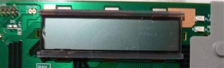
This is my screen:
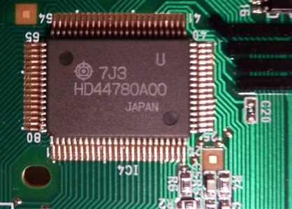
This is the chip:

How do I wire them togther (they are already on PCB togther)? How do I wire them to GPIO?
I can work off schematics and can follow very basic instructions (but can not compile software).