element14 Community
element14 Community
    Register Log In
  • Site
  • Search
  • Log In Register
  • Community Hub
    Community Hub
    • What's New on element14
    • Feedback and Support
    • Benefits of Membership
    • Personal Blogs
    • Members Area
    • Achievement Levels
  • Learn
    Learn
    • Ask an Expert
    • eBooks
    • element14 presents
    • Learning Center
    • Tech Spotlight
    • STEM Academy
    • Webinars, Training and Events
    • Learning Groups
  • Technologies
    Technologies
    • 3D Printing
    • FPGA
    • Industrial Automation
    • Internet of Things
    • Power & Energy
    • Sensors
    • Technology Groups
  • Challenges & Projects
    Challenges & Projects
    • Design Challenges
    • element14 presents Projects
    • Project14
    • Arduino Projects
    • Raspberry Pi Projects
    • Project Groups
  • Products
    Products
    • Arduino
    • Avnet Boards Community
    • Dev Tools
    • Manufacturers
    • Multicomp Pro
    • Product Groups
    • Raspberry Pi
    • RoadTests & Reviews
  • About Us
  • Store
    Store
    • Visit Your Store
    • Choose another store...
      • Europe
      •  Austria (German)
      •  Belgium (Dutch, French)
      •  Bulgaria (Bulgarian)
      •  Czech Republic (Czech)
      •  Denmark (Danish)
      •  Estonia (Estonian)
      •  Finland (Finnish)
      •  France (French)
      •  Germany (German)
      •  Hungary (Hungarian)
      •  Ireland
      •  Israel
      •  Italy (Italian)
      •  Latvia (Latvian)
      •  
      •  Lithuania (Lithuanian)
      •  Netherlands (Dutch)
      •  Norway (Norwegian)
      •  Poland (Polish)
      •  Portugal (Portuguese)
      •  Romania (Romanian)
      •  Russia (Russian)
      •  Slovakia (Slovak)
      •  Slovenia (Slovenian)
      •  Spain (Spanish)
      •  Sweden (Swedish)
      •  Switzerland(German, French)
      •  Turkey (Turkish)
      •  United Kingdom
      • Asia Pacific
      •  Australia
      •  China
      •  Hong Kong
      •  India
      •  Korea (Korean)
      •  Malaysia
      •  New Zealand
      •  Philippines
      •  Singapore
      •  Taiwan
      •  Thailand (Thai)
      • Americas
      •  Brazil (Portuguese)
      •  Canada
      •  Mexico (Spanish)
      •  United States
      Can't find the country/region you're looking for? Visit our export site or find a local distributor.
  • Translate
  • Profile
  • Settings
Raspberry Pi
  • Products
  • More
Raspberry Pi
Raspberry Pi Forum Peripheral Devices That I have but Don't know how to use. Help Please.
  • Blog
  • Forum
  • Documents
  • Quiz
  • Events
  • Polls
  • Files
  • Members
  • Mentions
  • Sub-Groups
  • Tags
  • More
  • Cancel
  • New
Join Raspberry Pi to participate - click to join for free!
Featured Articles
Announcing Pi
Technical Specifications
Raspberry Pi FAQs
Win a Pi
Raspberry Pi Wishlist
Actions
  • Share
  • More
  • Cancel
Forum Thread Details
  • Replies 20 replies
  • Subscribers 669 subscribers
  • Views 3243 views
  • Users 0 members are here
  • raspberry
  • of
  • people
  • the
  • pi
  • gpio
  • touch;
  • useful
  • rasp
  • what
  • display;
  • screen;
  • but
  • above
  • could
  • raspberry_pi
  • raspi;
  • used
  • see
  • thought
  • is
  • know
  • don't
  • rpi
  • with
  • be
  • thought.;
  • if
  • any
  • inch;
  • would
  • i
  • 4
  • pi;
Related

Peripheral Devices That I have but Don't know how to use. Help Please.

wallarug
wallarug over 13 years ago

I took apart a TomTom GPS the other day and stole the 4 Inch Display out of it along with a GPS module and SD card reader.


Specs of Dispaly:

     Touch Screen

     480x272 resolution

     NAME: LTE400WQ-E01-005

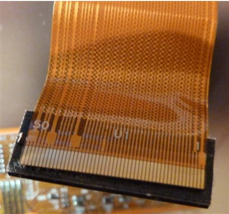
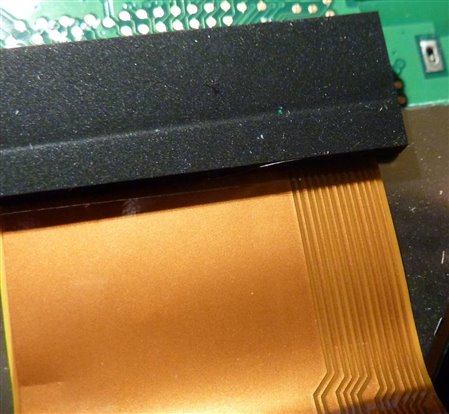
      50 pin connector (see below)

image


Can someone help me find a way that I can use this with my Raspberry Pi?  If someone could please find a datasheet first, that would be much appreciated.


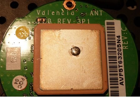
Specs of GPS module are not know except for the NAME: Valencia ANT PCB REV:3P1 (see below)

image

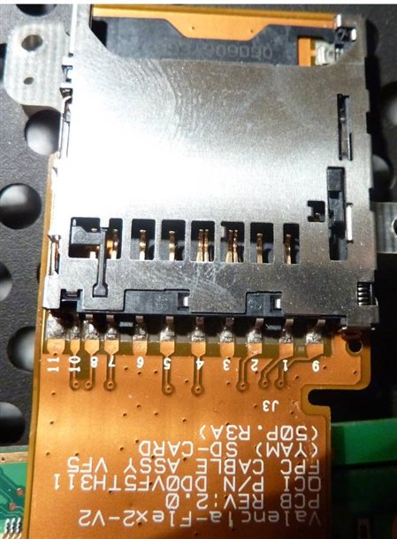
Specs of SD card Reader - only pictures. (see below)

Connector:

image

Reader:

image


I don't know if any of the above could be used / is useful with the Raspberry Pi but I thought I would see what people thought.


The one I really would Like to work with the Raspberry Pi is the touch display.  this would make my RPi somewhat portable and would be cool to have.


If the display can work with GPIO, then it would be nice to use with a rev 2 board with mounting holes.


Also, If the display works, then I thnk you can by these 4 Inch Touch Displays online from about $30 -$50 Dollars.


Thanks for any responces, they will be much apreicated.

  • Sign in to reply
  • Cancel
Parents
  • wallarug
    wallarug over 13 years ago

    Adding to the list of Devices that I can't use is an IC 7 Segment display Decoder (http://www.jaycar.com.au/products_uploaded/ZC4511.pdf).  I can wire the corresponding letters to the corresponding segments but I don't understand what some of the pins are:

    1. LE

    2. LT

    3. BT

    image


    On the Display itself, it has a pin marked Dp which I guess is the backlight.  Where does this go on the IC?

    image


    And it is a Common Cathode Display (I checked).


    Thanks in advance.

    • Cancel
    • Vote Up 0 Vote Down
    • Sign in to reply
    • Cancel
  • johnbeetem
    johnbeetem over 13 years ago in reply to wallarug

    Fergus Byrne wrote:


    Adding to the list of Devices that I can't use is an IC 7 Segment display Decoder (http://www.jaycar.com.au/products_uploaded/ZC4511.pdf).  I can wire the corresponding letters to the corresponding segments but I don't understand what some of the pins are:

    1. LE

    2. LT

    3. BT


    On the Display itself, it has a pin marked Dp which I guess is the backlight.  Where does this go on the IC?


    And it is a Common Cathode Display (I checked).


    Thanks in advance.

    The CD4511 data sheet describes ~LT, ~Bl, and LE in text and in the truth table.  ~LT is "Lamp Test" and when low turns on all segments.  ~LT has priority over all other inputs.  ~Bl is "Blanking" and when low turns all segments off, assuming ~LT is high = inactive.  ~Bl is used to blank the display to save power or can control brightness using pulse width modulation, i.e., with a variable duty cycle.  It has priority over LE.  LE is "Latch Enable" and when high stores the DCBA input that was present when LE rose from 0 to 1.  If LE = 0, the latch is transparent and segments a-g follow DCBA.  If LE = 1, the CD4511 ignores the DCBA inputs and displays the stored DCBA value.  LE is useful if you want to drive multiple digits from RasPi's limited GPIO signals since you can share the DCBA signals and provide a separate LE for each digit.


    CD4511 a-g outputs are active high and need to be used with a common cathode LED array.


    The decimal point DP is not controlled by the CD4511 and if used must be driven with other circuits.

    • Cancel
    • Vote Up 0 Vote Down
    • Sign in to reply
    • Cancel
  • wallarug
    wallarug over 13 years ago in reply to johnbeetem

    I have now wired the chip as per the specifications above ^.

    Can someone please check my code and tell me why it won't work please.

    import RPi.GPIO as GPIO

    GPIO.setmode(GPIO.BOARD)

    GPIO.setup(7, GPIO.OUT)

    GPIO.setup(11, GPIO.OUT)

    GPIO.setup(12, GPIO.OUT)

    GPIO.setup(13, GPIO.OUT)


    # 7 = Decoder A   2^0 = 1

    # 11 = Decoder B  2^1 = 2

    # 12 = Decoder C  2^2 = 4

    # 13 = Decoder D  2^3 = 8


    i = input("Enter the Number 0 - 9: ")

    while i!="":

              if i=="0":

                        GPIO.output(7, GPIO.HIGH)

                        GPIO.output(11, GPIO.HIGH)

                        GPIO.output(12, GPIO.HIGH)

                        GPIO.output(13, GPIO.HIGH)

              elif i=="1":

                        GPIO.output(7, GPIO.LOW)

                        GPIO.output(11, GPIO.HIGH)

                        GPIO.output(12, GPIO.HIGH)

                        GPIO.output(13, GPIO.HIGH)

              elif i=="2":

                        GPIO.output(7, GPIO.HIGH)

                        GPIO.output(11, GPIO.LOW)

                        GPIO.output(12, GPIO.HIGH)

                        GPIO.output(13, GPIO.LOW)

              elif i=="3":

                        GPIO.output(7, GPIO.LOW)

                        GPIO.output(11, GPIO.HIGH)

                        GPIO.output(12, GPIO.HIGH)

                        GPIO.output(13, GPIO.HIGH)

              elif i=="4":

                        GPIO.output(7, GPIO.HIGH)

                        GPIO.output(11, GPIO.HIGH)

                        GPIO.output(12, GPIO.LOW)

                        GPIO.output(13, GPIO.HIGH)

              elif i=="5":

                        GPIO.output(7, GPIO.LOW)

                        GPIO.output(11, GPIO.HIGH)

                        GPIO.output(12, GPIO.LOW)

                        GPIO.output(13, GPIO.HIGH)

              elif i=="6":

                        GPIO.output(7, GPIO.HIGH)

                        GPIO.output(11, GPIO.LOW)

                        GPIO.output(12, GPIO.LOW)

                        GPIO.output(13, GPIO.HIGH)

              elif i=="7":

                        GPIO.output(7, GPIO.LOW)

                        GPIO.output(11, GPIO.LOW)

                        GPIO.output(12, GPIO.LOW)

                        GPIO.output(13, GPIO.HIGH)

              elif i=="8":

                        GPIO.output(7, GPIO.HIGH)

                        GPIO.output(11, GPIO.HIGH)

                        GPIO.output(12, GPIO.HIGH)

                        GPIO.output(13, GPIO.LOW)

              elif i=="9":

                        GPIO.output(7, GPIO.LOW)

                        GPIO.output(11, GPIO.HIGH)

                        GPIO.output(12, GPIO.HIGH)

                        GPIO.output(13, GPIO.LOW)

              else:

                        print "You didn't enter a valid number!"


              i = input("Enter the Number 0 - 9: ")

    if: i == "":

              print "Closing application..."

    It just skips to the else statement with in the while statement. here the statements are not nested but in my code, they are nested.

    • Cancel
    • Vote Up 0 Vote Down
    • Sign in to reply
    • Cancel
  • wallarug
    wallarug over 13 years ago in reply to johnbeetem

    image

    Bit of a mess but here is a schematic of what I have wired up.  Last night, I had power going into the DP and a little light came on but today that is not happening.  Have I blown the chip?

    • Cancel
    • Vote Up 0 Vote Down
    • Sign in to reply
    • Cancel
  • Former Member
    Former Member over 13 years ago in reply to wallarug

    >  i = input("Enter the Number 0 - 9: ")


    I think you want raw_intput instead of input.

    The difference is that input accepts commands and tries to evaluate them,

    which probably isn't what you want, although it wouldn't matter if the user

    just types digits.


    > if i=="0":


    I don't think you want the quotes around 0, since the variable i

    holds an integer.  The input function automatically converts to integer

    when it can.


    In case 2, output 13 should be high.

    In case 3, output 11 should be low.

    • Cancel
    • Vote Up 0 Vote Down
    • Sign in to reply
    • Cancel
  • wallarug
    wallarug over 13 years ago in reply to Former Member

    What about the wiring above?  Is it good?

    • Cancel
    • Vote Up 0 Vote Down
    • Sign in to reply
    • Cancel
  • Former Member
    Former Member over 13 years ago in reply to wallarug

    it doesn't have any obvious flaws.

    I'm not qualified to find any subtle flaws.

    • Cancel
    • Vote Up 0 Vote Down
    • Sign in to reply
    • Cancel
  • johnbeetem
    johnbeetem over 13 years ago in reply to wallarug

    Fergus Byrne wrote:


    Bit of a mess but here is a schematic of what I have wired up.  Last night, I had power going into the DP and a little light came on but today that is not happening.  Have I blown the chip?

    I don't see any current limiting resistors in your diagram.  Typical LEDs use 1.6V (red) to 2.4V (green).  If you put 3.3V across them without current limiting they will emit a lot of light -- once.  Then they'll be DED.  Driving one directly from a RasPi BCM2835 output without current limit could also damage the BCM2835 output.


    I just checked Wikipedia.  They have a thorough article on LEDs and also one that shows how to power an LED using a current limiting resistor and how to calculate its value.  Typical values are 150 Ohm to 1K Ohm depending on the driver voltage, the LED's efficiency and how bright you want it to be.

    • Cancel
    • Vote Up 0 Vote Down
    • Sign in to reply
    • Cancel
  • wallarug
    wallarug over 13 years ago in reply to johnbeetem

    So you think I have "blown the bolb" on the 7 segment display?  If so, that would mean that the IC is still in place and I can get up and running when I get a new 7 segment dispaly...Right?

    • Cancel
    • Vote Up 0 Vote Down
    • Sign in to reply
    • Cancel
  • johnbeetem
    johnbeetem over 13 years ago in reply to wallarug

    Fergus Byrne wrote:


    So you think I have "blown the bolb" on the 7 segment display?  If so, that would mean that the IC is still in place and I can get up and running when I get a new 7 segment dispaly...Right?

    You've probably only destroyed the DP LED.  If you didn't see a bright flash from the other segments, they're probably still intact.  It all depends on what the CD4511 DCBA inputs were when you powered it on.  If DCBA are 1010 through 1111 then outputs a-g are low and the LEDs aren't driven.  With the CD4511 disconnected, try powerering each LED segment from +3.3V through a 150-300 Ohm resistor and see which ones still light up.

    • Cancel
    • Vote Up 0 Vote Down
    • Sign in to reply
    • Cancel
  • bodgy
    bodgy over 13 years ago in reply to wallarug

    You could test your display by using the diode test setting on a multimeter.


    If your meter is digital, the negative lead goes to the CC connection and then one by one place the positive lead on the segment pins, each segment will light. Possibly very faintly, depends on the actual display involved.


    If your meter is an analogue one (it has a needle meter), then you might need to reverse the connections above. The meter is unlikely to give more than 2v and will be low current.

    • Cancel
    • Vote Up +1 Vote Down
    • Sign in to reply
    • Cancel
  • wallarug
    wallarug over 13 years ago in reply to bodgy

    Will look into it when I get back from holidays.  Thanks for responce.

    • Cancel
    • Vote Up 0 Vote Down
    • Sign in to reply
    • Cancel
Reply
  • wallarug
    wallarug over 13 years ago in reply to bodgy

    Will look into it when I get back from holidays.  Thanks for responce.

    • Cancel
    • Vote Up 0 Vote Down
    • Sign in to reply
    • Cancel
Children
No Data
element14 Community

element14 is the first online community specifically for engineers. Connect with your peers and get expert answers to your questions.

  • Members
  • Learn
  • Technologies
  • Challenges & Projects
  • Products
  • Store
  • About Us
  • Feedback & Support
  • FAQs
  • Terms of Use
  • Privacy Policy
  • Legal and Copyright Notices
  • Sitemap
  • Cookies

An Avnet Company © 2025 Premier Farnell Limited. All Rights Reserved.

Premier Farnell Ltd, registered in England and Wales (no 00876412), registered office: Farnell House, Forge Lane, Leeds LS12 2NE.

ICP 备案号 10220084.

Follow element14

  • X
  • Facebook
  • linkedin
  • YouTube