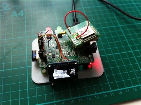
The previous Wolfson card has a 26 pin header with male pins to connect to the Raspberry GPIO header after pushed on top of it. Does the new audio card do the same for the 40 pin header? Sorry, but I cannot discern from the card images I have.
Hi Zsolt,
The circuit diagram is here: http://www.element14.com/community/docs/DOC-72041/l/cirrus-logic-audio-card-for-b-and-a-onwards-schematics
It looks like a few GPIO are on an expansion header as you can see from there, but not all.
Thank you both. From the schematics I see they use the I2C and SPI pins, for example, but there is no sign of them passing out, to connect other devices. (although they are designed to connect several devices, not only one, isn't it?) With the Raspberry model B, we had, beside the I2C (2 pins) and SPI (4 pins) other 11 pins for general IO, with the model B+ this increased to at least 20 - so 26 pins, counting the 6 mentioned ones. Now on the Cirrus card expansion header I see 6 pins for general IO, plus some pins I don't understand. There is no mention of SPI, there is SDA and SCLK (Control Interface - what does it mean?) which resemble the I2C (just the clock was named SCL, and "Control Interface clock input" is a bit confusing, because I2C clocks can be output as well, as I know), and a few pins I don't understand. The Audio Interface 3 seems to refer to the SPDIF, isn't it? There are also 2 pins for a "Digital speaker", what can be very cool, I assume (for audiophiles). So if I put in Cirrus, it looks like the whole Raspberry is converted to a super audio card, with a lot of audio inputs and outputs. If I want to do some other stuff, I should content myself with a total of 6 GPIO pins (and this with the model B+). Cool, isn't it?
I'm currently working on a project with the A+ and the Cirrus Logic audio card. I needed to connect a I2C display and another module using UART.
I was able to find all the pins on the expansion header. Not totally practical, but it works.
I would have preferred stacking headers on the audio card to still be able to use the available pins as is, without being forced to use the expansion header layout.
Frederick
I wander where you found them (and how). If it's not documented, then it can be a field for hacking it (I can imagine, for example taking pins from the original header, by some hack soldering, and checking if they are used with a logic analyzer.) There is no documentation of what is really *used* from the 40 pins. I have an LCD display which only takes 7 pins by itself (not counting the other bits). But why should I do hacking? The engineers at Cirrus clearly haven't done a correct job. When you install a tumble dryer, you don't take over all the doors and windows in the house. Shame.
In this table (e), pins 16-20 are ALL described as "General Purpose Pin GPIO 3", which looks to me like a copy/paste error from the pin 15 description.
It would be nicer if table (e) were to read:
| Pin | Name | Type | Power Domain | Description |
|---|---|---|---|---|
| 17 | GPIO6_EX | Digital In/Out | 0 - 3.3V | RPI General Purpose Pin GPIO6 (RPI pin 31) |
| 18 | GPIO12_EX | Digital In/Out | 0 - 3.3V | RPI General Purpose Pin GPIO12 (RPI pin 32) |
| 19 | GPIO16_EX | Digital In/Out | 0 - 3.3V | RPI General Purpose Pin GPIO16 (RPI pin 36) |
| 20 | GPIO26_EX | Digital In/Out | 0 - 3.3V | RPI General Purpose Pin GPIO26 (RPI pin 37) |
However, there are discrepancies between this table (e) and the description within the schematic that need to be figured out.
Pins 10 and 11 are flipped between the schematic and table (e). (In the schematic, pin 10 is listed as PDMOUT_DAT [3] while table (e) says pin 10 is SDA. And vice versa for pin 11.) Which is correct?
In the schematic, pin 14 is listed as connected to "GPIO5_EX [7]", which SHOULD correspond to PI GPIO 5 (PI pin 29). However table (e) lists pin 14 as being GND. Which is correct?
In the Cirrus Logic Audio Card Comparison Table, it says that there are 8 PI connections (including the UART). The UART is connected to the Cirrus J8 Header. (RPI pins 8&10)
Can anyone confirm definitively which are the other two GPIO pins that are tied directly from the PI into the Cirrus expansion header?
Any definitive clues?
Good call. I've seen only now the whole schematics, sorry.
Yes, some of these errors I pointed out too in my comments to the CL manual.
Pin 14 is GPIO 5 for sure. It is wired physically to the Pin 29 in 40-pin header.
Pin 11 (Not Pin 10!) is wired to the Pin 03 of 40-pin header - GPIO 2 (SDA1, I2C). So, Pin 10 could be PDMDAT.
As far as Pin 09 is SCL, and (I checked) it is connected to the Pin 05 of 40-pin header - it's GPIO 3. So the Pin 16 of Expansion header should be something else.
Both of pins 15 and 16 are not connected to any of pins of 40-pin header.
So we have 6 GPIOs that are tied directly from the RPI into the Cirrus L Expansion header (Pins 09, 11, 14, 17, 18, 19, 20).
This is what can be easily verified by a simple multimeter.