element14 Community
element14 Community
    Register Log In
  • Site
  • Search
  • Log In Register
  • Community Hub
    Community Hub
    • What's New on element14
    • Feedback and Support
    • Benefits of Membership
    • Personal Blogs
    • Members Area
    • Achievement Levels
  • Learn
    Learn
    • Ask an Expert
    • eBooks
    • element14 presents
    • Learning Center
    • Tech Spotlight
    • STEM Academy
    • Webinars, Training and Events
    • Learning Groups
  • Technologies
    Technologies
    • 3D Printing
    • FPGA
    • Industrial Automation
    • Internet of Things
    • Power & Energy
    • Sensors
    • Technology Groups
  • Challenges & Projects
    Challenges & Projects
    • Design Challenges
    • element14 presents Projects
    • Project14
    • Arduino Projects
    • Raspberry Pi Projects
    • Project Groups
  • Products
    Products
    • Arduino
    • Avnet & Tria Boards Community
    • Dev Tools
    • Manufacturers
    • Multicomp Pro
    • Product Groups
    • Raspberry Pi
    • RoadTests & Reviews
  • About Us
    About the element14 Community
  • Store
    Store
    • Visit Your Store
    • Choose another store...
      • Europe
      •  Austria (German)
      •  Belgium (Dutch, French)
      •  Bulgaria (Bulgarian)
      •  Czech Republic (Czech)
      •  Denmark (Danish)
      •  Estonia (Estonian)
      •  Finland (Finnish)
      •  France (French)
      •  Germany (German)
      •  Hungary (Hungarian)
      •  Ireland
      •  Israel
      •  Italy (Italian)
      •  Latvia (Latvian)
      •  
      •  Lithuania (Lithuanian)
      •  Netherlands (Dutch)
      •  Norway (Norwegian)
      •  Poland (Polish)
      •  Portugal (Portuguese)
      •  Romania (Romanian)
      •  Russia (Russian)
      •  Slovakia (Slovak)
      •  Slovenia (Slovenian)
      •  Spain (Spanish)
      •  Sweden (Swedish)
      •  Switzerland(German, French)
      •  Turkey (Turkish)
      •  United Kingdom
      • Asia Pacific
      •  Australia
      •  China
      •  Hong Kong
      •  India
      •  Japan
      •  Korea (Korean)
      •  Malaysia
      •  New Zealand
      •  Philippines
      •  Singapore
      •  Taiwan
      •  Thailand (Thai)
      •  Vietnam
      • Americas
      •  Brazil (Portuguese)
      •  Canada
      •  Mexico (Spanish)
      •  United States
      Can't find the country/region you're looking for? Visit our export site or find a local distributor.
  • Translate
  • Profile
  • Settings
Raspberry Pi
  • Products
  • More
Raspberry Pi
Raspberry Pi Forum Velleman K2633 Relay Card Troubleshooting
  • Blog
  • Forum
  • Documents
  • Quiz
  • Events
  • Polls
  • Files
  • Members
  • Mentions
  • Sub-Groups
  • Tags
  • More
  • Cancel
  • New
Join Raspberry Pi to participate - click to join for free!
Featured Articles
Announcing Pi
Technical Specifications
Raspberry Pi FAQs
Win a Pi
Raspberry Pi Wishlist
Actions
  • Share
  • More
  • Cancel
Forum Thread Details
  • State Verified Answer
  • Replies 7 replies
  • Answers 4 answers
  • Subscribers 708 subscribers
  • Views 1941 views
  • Users 0 members are here
  • raspberry_pi
Related

Velleman K2633 Relay Card Troubleshooting

mattwilliams
mattwilliams over 9 years ago

Good day.


I get unexpected results when connecting a K2633 relay card to my Raspberry Pi 3 and hope someone can help.


When my Python 3 code sends 3.3V from any GPIO pin to any IN pin on K2633, the K2633 LED on that channel lights, but that relay does not energize. This occurs when the K2633 is supplied with either 5VDC from the RPi or 9VDC from a separate and isolated supply.


The four K2633 SPDT relays are 6V units. K2633 product literature calls for a 9V power supply - which I have. I realize that 5V from RPi is not enough voltage to energize the relays.


K2633 is built correctly and any relay can be forced to function properly by supplying 9VDC to the K2633 and shorting any IN pin to GND. In such a case, that particular relay will energize. Do I need to program an RPi GPIO pin to go to GND when I want to energize the relay? If so, I am not aware of how this is possible - since I understand output pins to only be capable of either zero or 3.3V when defined as outputs - with zero volts not meaning 'connected to GND'. Do I correctly understand this item?


This is a breadboard setup for proof of concept to control any relay and with nothing presently connected to C, NO or NC terminals, so final switching application is unrelated to problem. Final application will be to switch a US 110 VAC / 90 Watt ceiling fan on and off. The fan's power ratings are within the relays' capabilities of 15 A / 125 VAC. Is a different relay card a better choice?


RPi and code function properly - since I can turn on and off an LED with the circuit / program in addition to seeing 3.3V at any K2633 IN pin with a multimeter.


Thank you for any direction you might be able to offer.


Matt

  • Sign in to reply
  • Cancel
  • D_Hersey
    0 D_Hersey over 9 years ago

    'Tri-state' means not connected to anything.  'Positive logic low' means connected to (logic) PS-.  I would also check my current requirements

    • Cancel
    • Vote Up 0 Vote Down
    • Sign in to reply
    • Verify Answer
    • Reject Answer
    • Cancel
  • mcb1
    0 mcb1 over 9 years ago

    The linked schematic is a bit blurry but if I read it right it uses PNP transistors that feed the 9v to the coil.

    This means the base of the transistor will be about 8.3v and far too high for the Raspberry Pi.


    You'll need to add a transisor or an optocoupler between the RPi GPIO and the relay control pin.


    Do I need to program an RPi GPIO pin to go to GND when I want to energize the relay?

    Yes you will BUT you cannot connect the 8.3v input to the RPi GPIO.

    This is referred to as ACTIVE LOW meaning the circuit is active/on when it is low.


    The ground of the supply for the relay and the RPi ground should be connected, and then when the GPIO is LOW it would turn ON

    BUT again with the 8.3v you shouldn't.


    If you use an optocoupler you wouldn't need to connect the two.


    Hope this helps.

    Mark

    • Cancel
    • Vote Up +2 Vote Down
    • Sign in to reply
    • Verify Answer
    • Reject Answer
    • Cancel
  • shabaz
    0 shabaz over 9 years ago

    Hi Matt,


    There are a few things.

    Firstly, the card isn't designed to run with the Pi's output, it is designed for Velleman's USB controller card which offers a higher current 'open collector' design.

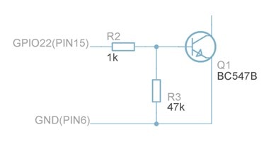
    So, you'd need an interface circuit between the Pi and the relay card. See Raspberry Pi GPIO Explained in the "Understanding Raspberry Pi Outputs" section, click on "Output Design Tips" tab, and you'll see a couple of circuits using a BC547 transistor.

    Use that circuit (remove the blue LED and its 120 ohm resistor n the first circuit, and connect up the relay card input to the top (collector) end of the transistor). The part of the circuit you need is replicated here. The GND connection in this circuit connects to the relay card too.

    image

    Secondly, I think there are better (safer) ways than using that card. Instead, something like this could be used and placed inside an enclosure with secured wiring:

    DR48D03R - CRYDOM - Solid State Relay, 3 A, 600 VAC, DIN Rail, Screw, Random Turn On | Newark element14

    To use that, you'll still need the interface circuit (like the BC547 one) however. Power it from 5V if you like, it doesn't need 9V but it needs more than 4V. To use the SSR, connect the negative end of the SSR control input to the top of the transistor in the diagram, and connect the positive end of the control input to the 5V or 9V supply.


    Thirdly, the above first and second points assume you know what you're doing and know how to make what you're doing safe, and that it is legal in your country to do this (it isn't legal in all countries for a consumer to tamper with home wiring).

    If the above assumptions cannot be satisfied, then you should seek a safer consumer option like any home automation product (google home automation to find products certified for your country). Most of them rely on a simple wireless method (at 433MHz for example), or on a network connection (using Wi-Fi for the connectivity usually), and it becomes a software exercise to interface to it on the control side.

    • Cancel
    • Vote Up +2 Vote Down
    • Sign in to reply
    • Verify Answer
    • Reject Answer
    • Cancel
  • mattwilliams
    0 mattwilliams over 9 years ago in reply to shabaz

    Thanks to all of you who replied. I can see that you have given this quite a bit of thought - I appreciate that.


    Yes - what I am doing is safe and legal - thank you for mentioning the importance of this.


    Matt

    • Cancel
    • Vote Up 0 Vote Down
    • Sign in to reply
    • Verify Answer
    • Cancel
  • COMPACT
    0 COMPACT over 9 years ago in reply to D_Hersey

    That's a pretty high impedance statement!

    • Cancel
    • Vote Up 0 Vote Down
    • Sign in to reply
    • Verify Answer
    • Cancel
  • Robert Peter Oakes
    0 Robert Peter Oakes over 9 years ago in reply to D_Hersey

    Technically TriState does not mean not connected. It means not driving it to one level or another (0 or 1 in this case). It is simply a High Impedance state on the pin, for instance when you switch it from an output to an input.

    Or if your sharing the pin with other drivers, this pin is opting not to affect the level of the wire.

    • Cancel
    • Vote Up +1 Vote Down
    • Sign in to reply
    • Verify Answer
    • Reject Answer
    • Cancel
  • jc2048
    0 jc2048 over 9 years ago in reply to mattwilliams

    You might consider adapting the circuit on the board to be the circuit Shabaz shows (by turning the board circuit upside down).


    If you substitute NPN transistors for the PNPs, turn the diodes round, put links in place of the LEDs, apply the power the other way round (plus to minus and minus to plus), then you'd be able to drive it from the Pi (remembering that the + on the input connector is now really the GND). You'd lose the LEDs but save yourself the bother of wiring up another board. You might even get the LEDs to work (they'd need to be turned round, too), but it's a bit tight if the Pi GPIO is 3.3V - you'd have a job getting the Rx resistor value right.


    I'm assuming that the relays don't have protection diodes built in - this wouldn't work if they do.

    • Cancel
    • Vote Up +2 Vote Down
    • Sign in to reply
    • Verify Answer
    • Reject Answer
    • Cancel
element14 Community

element14 is the first online community specifically for engineers. Connect with your peers and get expert answers to your questions.

  • Members
  • Learn
  • Technologies
  • Challenges & Projects
  • Products
  • Store
  • About Us
  • Feedback & Support
  • FAQs
  • Terms of Use
  • Privacy Policy
  • Legal and Copyright Notices
  • Sitemap
  • Cookies

An Avnet Company © 2026 Premier Farnell Limited. All Rights Reserved.

Premier Farnell Ltd, registered in England and Wales (no 00876412), registered office: Farnell House, Forge Lane, Leeds LS12 2NE.

Follow element14

  • X
  • Facebook
  • linkedin
  • YouTube