element14 Community
element14 Community
    Register Log In
  • Site
  • Search
  • Log In Register
  • Community Hub
    Community Hub
    • What's New on element14
    • Feedback and Support
    • Benefits of Membership
    • Personal Blogs
    • Members Area
    • Achievement Levels
  • Learn
    Learn
    • Ask an Expert
    • eBooks
    • element14 presents
    • Learning Center
    • Tech Spotlight
    • STEM Academy
    • Webinars, Training and Events
    • Learning Groups
  • Technologies
    Technologies
    • 3D Printing
    • FPGA
    • Industrial Automation
    • Internet of Things
    • Power & Energy
    • Sensors
    • Technology Groups
  • Challenges & Projects
    Challenges & Projects
    • Design Challenges
    • element14 presents Projects
    • Project14
    • Arduino Projects
    • Raspberry Pi Projects
    • Project Groups
  • Products
    Products
    • Arduino
    • Avnet Boards Community
    • Dev Tools
    • Manufacturers
    • Multicomp Pro
    • Product Groups
    • Raspberry Pi
    • RoadTests & Reviews
  • Store
    Store
    • Visit Your Store
    • Choose another store...
      • Europe
      •  Austria (German)
      •  Belgium (Dutch, French)
      •  Bulgaria (Bulgarian)
      •  Czech Republic (Czech)
      •  Denmark (Danish)
      •  Estonia (Estonian)
      •  Finland (Finnish)
      •  France (French)
      •  Germany (German)
      •  Hungary (Hungarian)
      •  Ireland
      •  Israel
      •  Italy (Italian)
      •  Latvia (Latvian)
      •  
      •  Lithuania (Lithuanian)
      •  Netherlands (Dutch)
      •  Norway (Norwegian)
      •  Poland (Polish)
      •  Portugal (Portuguese)
      •  Romania (Romanian)
      •  Russia (Russian)
      •  Slovakia (Slovak)
      •  Slovenia (Slovenian)
      •  Spain (Spanish)
      •  Sweden (Swedish)
      •  Switzerland(German, French)
      •  Turkey (Turkish)
      •  United Kingdom
      • Asia Pacific
      •  Australia
      •  China
      •  Hong Kong
      •  India
      •  Korea (Korean)
      •  Malaysia
      •  New Zealand
      •  Philippines
      •  Singapore
      •  Taiwan
      •  Thailand (Thai)
      • Americas
      •  Brazil (Portuguese)
      •  Canada
      •  Mexico (Spanish)
      •  United States
      Can't find the country/region you're looking for? Visit our export site or find a local distributor.
  • Translate
  • Profile
  • Settings
Raspberry Pi
  • Products
  • More
Raspberry Pi
Raspberry Pi Forum How to connect a ADAFRUIT16x32 RGB LED Matrix Panel to a Raspberry Pi 4
  • Blog
  • Forum
  • Documents
  • Quiz
  • Events
  • Polls
  • Files
  • Members
  • Mentions
  • Sub-Groups
  • Tags
  • More
  • Cancel
  • New
Join Raspberry Pi to participate - click to join for free!
Featured Articles
Announcing Pi
Technical Specifications
Raspberry Pi FAQs
Win a Pi
Raspberry Pi Wishlist
Actions
  • Share
  • More
  • Cancel
Forum Thread Details
  • State Suggested Answer
  • Replies 15 replies
  • Answers 7 answers
  • Subscribers 664 subscribers
  • Views 3914 views
  • Users 0 members are here
  • raspberry_pi
Related

How to connect a ADAFRUIT16x32 RGB LED Matrix Panel to a Raspberry Pi 4

harness68
harness68 over 5 years ago

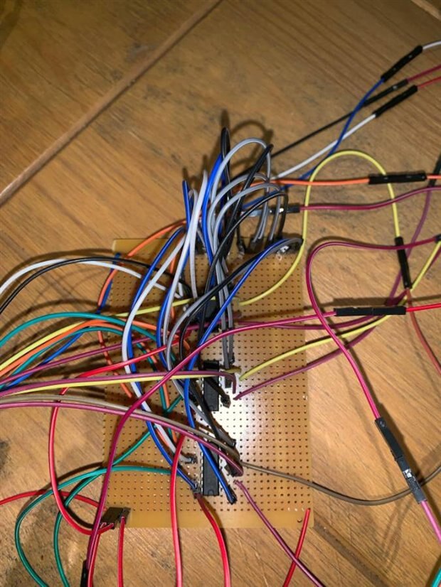
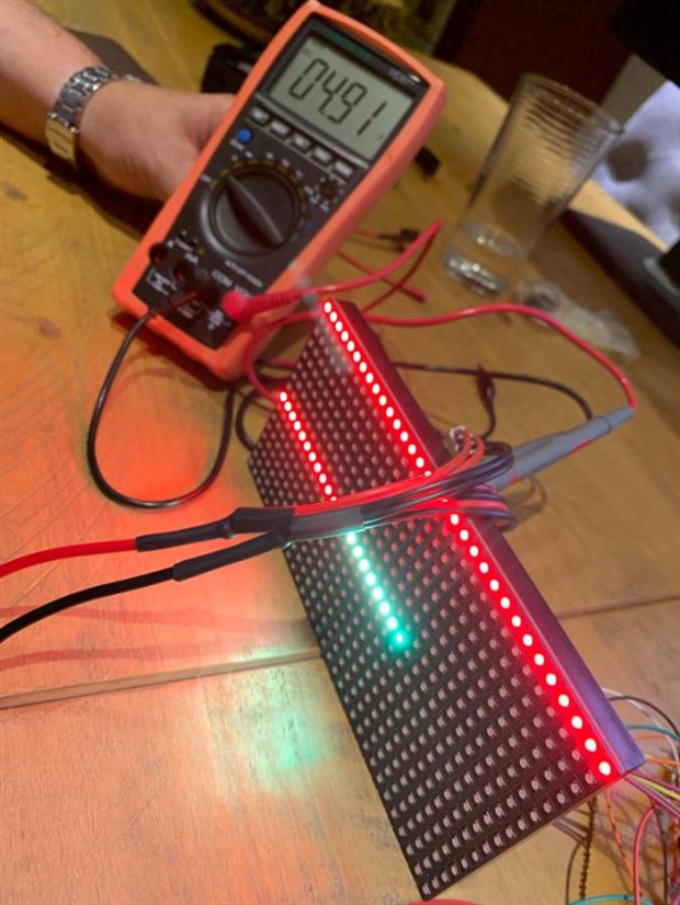
I am having difficulty.  I assume I have connected the 16x32 RGB LED Matrix Panel to a Raspberry Pi 4 I have but It never displays.  I have followed all the tutorials on ADAFRUIT but they only confirm the pin out connection to a Pi3.  has anyone ever got this to work?

  • Sign in to reply
  • Cancel
  • clem57
    0 clem57 over 5 years ago

    harness68  What software did you try? Do you have a digital meter to check the voltage changes to the panel? I have done simple LED's with no problem. My suggestion is check for the obvious before going too deep.

    Clem

    • Cancel
    • Vote Up 0 Vote Down
    • Sign in to reply
    • Verify Answer
    • Reject Answer
    • Cancel
  • harness68
    0 harness68 over 5 years ago in reply to clem57

    I did check the power and it was at 5 v  I think I need to double check the jumper connections to the 40 pin connector.  As for the software I used the suggested software (https://github.com/hzeller/rpi-rgb-led- ... es-api-use)

    It did give me a few issues at the command line

    • Cancel
    • Vote Up 0 Vote Down
    • Sign in to reply
    • Verify Answer
    • Cancel
  • clem57
    0 clem57 over 5 years ago in reply to harness68

    Good voltage of 5 V. It also suggested to supply around 2 amps externally and not from the Pi. Also in terms of software, the GPIO pins need to act as a PWM switch on and off at a frequency or duty cycle to make the LED's "glow". The faster the switching, the brighter the "glow". An Arduino has hardware and CPU dedicated to do this whereas the Raspberry Pi relies on software OS and is less deterministic.


    Keep in mind that these displays are designed to be driven by FPGAs or other high speed processors: they do not have built in PWM control of any kind. Instead, you're supposed to redraw the screen over and over to 'manually' PWM the whole thing. On a 16 MHz arduino, we managed to squeeze 12-bit color (4096 colors) with 20% CPU usage but this display would really shine if driven by any FPGA, CPLD, Propeller, XMOS or other high speed multi-core controller. The good news is that the display is pre-white balanced with nice uniformity so if you turn on all the LEDs its not a particularly tinted white.

    The above to me says the Raspberry Pi not very well suited although may be workable. If the Raspberry Pi gets busy CPU wise, the GPIO pins may not be driven at the desired rate due to interference. I have not examined the demo software to understand how it works.


    Clem

    • Cancel
    • Vote Up +1 Vote Down
    • Sign in to reply
    • Verify Answer
    • Reject Answer
    • Cancel
  • clem57
    0 clem57 over 5 years ago

    Well I did more research and you cannot handle this on a Raspberry Pi as is:


    The GPIO pins are connected to the +3.3V rails. When used for input they are able to read voltages. When used for output they may be set to +3.3V (high) or 0V (low). There are 4 different types of GPIO pins on the Raspberry Pi.

    Because the Pi is 3.3V and the Adafruit 16x32 RGB LED Matrix Panel is 5 V, just connecting it would not work. But not all is lost. Look at https://www.sparkfun.com/products/12009  which convert both directions for this problem. Make sure to get enough for all the pins you will be using.

    • Cancel
    • Vote Up +2 Vote Down
    • Sign in to reply
    • Verify Answer
    • Cancel
  • clem57
    0 clem57 over 5 years ago

    https://learn.adafruit.com/adafruit-rgb-matrix-plus-real-time-clock-hat-for-raspberry-pi The Hat does the same thing as above.

    Clem


    Image of display.

    • Cancel
    • Vote Up +3 Vote Down
    • Sign in to reply
    • Verify Answer
    • Cancel
  • shabaz
    0 shabaz over 5 years ago

    As Clem says, it's very likely that the logic levels are incompatible. A lot of these 5V display boards use older logic ICs with non-3.3V-compatible inputs, and you'll either get nothing on the display, or stuff that looks like it sometimes works with corruption.

    There's also a high chance of power related issues, or software issues, if you're trying with a different version Pi. So, it's not surprising it isn't working. But, without photos showing your setup, including power source, and the output you got when installing and running the code (since you mention it did give you issues) it isn't possible to troubleshoot those aspects easily.

    • Cancel
    • Vote Up +4 Vote Down
    • Sign in to reply
    • Verify Answer
    • Reject Answer
    • Cancel
  • Problemchild
    0 Problemchild over 5 years ago in reply to shabaz

    Definitely  a 3.3-5v voltage level problem. I've not used their display but many others and they are all 5V using TTL shift registers for the most part and often CMOS so the 3.3v logic will be out of spec.

    Notice on the LED hat they use a separate 5V input and a 5V levelshifter. a bunch of transistors would do it as well up to you ...fortunately the levelshifting is all one way so easy enough!!

    • Cancel
    • Vote Up +4 Vote Down
    • Sign in to reply
    • Verify Answer
    • Reject Answer
    • Cancel
  • harness68
    0 harness68 over 5 years ago in reply to clem57

    LX Terminal on a raspberry pi 4 with a github link found on the ada fruit website, we have produced a breadboard with 3v to 5v conversion (74ahct125N) however when we run a demo,


    sudo ./demo -t 10 -D1 runtext.ppm


    only two lines of leds light up.


    we have tried changing the Columns and rows to 16x32 but still no change, we have checked to see if there is no shorts with a meter, we are definitely getting 5v  we have had to assume that the GPIO pin are in the same location on the Pi 4


    PLZ help / Advise image

    • Cancel
    • Vote Up 0 Vote Down
    • Sign in to reply
    • Verify Answer
    • Cancel
  • harness68
    0 harness68 over 5 years ago in reply to clem57

    Done, still got problems

    • Cancel
    • Vote Up 0 Vote Down
    • Sign in to reply
    • Verify Answer
    • Cancel
  • harness68
    0 harness68 over 5 years ago in reply to shabaz

    imageimageimageimage

    • Cancel
    • Vote Up 0 Vote Down
    • Sign in to reply
    • Verify Answer
    • Cancel
>
element14 Community

element14 is the first online community specifically for engineers. Connect with your peers and get expert answers to your questions.

  • Members
  • Learn
  • Technologies
  • Challenges & Projects
  • Products
  • Store
  • About Us
  • Feedback & Support
  • FAQs
  • Terms of Use
  • Privacy Policy
  • Legal and Copyright Notices
  • Sitemap
  • Cookies

An Avnet Company © 2025 Premier Farnell Limited. All Rights Reserved.

Premier Farnell Ltd, registered in England and Wales (no 00876412), registered office: Farnell House, Forge Lane, Leeds LS12 2NE.

ICP 备案号 10220084.

Follow element14

  • X
  • Facebook
  • linkedin
  • YouTube