element14 Community
element14 Community
    Register Log In
  • Site
  • Search
  • Log In Register
  • Community Hub
    Community Hub
    • What's New on element14
    • Feedback and Support
    • Benefits of Membership
    • Personal Blogs
    • Members Area
    • Achievement Levels
  • Learn
    Learn
    • Ask an Expert
    • eBooks
    • element14 presents
    • Learning Center
    • Tech Spotlight
    • STEM Academy
    • Webinars, Training and Events
    • Learning Groups
  • Technologies
    Technologies
    • 3D Printing
    • FPGA
    • Industrial Automation
    • Internet of Things
    • Power & Energy
    • Sensors
    • Technology Groups
  • Challenges & Projects
    Challenges & Projects
    • Design Challenges
    • element14 presents Projects
    • Project14
    • Arduino Projects
    • Raspberry Pi Projects
    • Project Groups
  • Products
    Products
    • Arduino
    • Avnet Boards Community
    • Dev Tools
    • Manufacturers
    • Multicomp Pro
    • Product Groups
    • Raspberry Pi
    • RoadTests & Reviews
  • About Us
  • Store
    Store
    • Visit Your Store
    • Choose another store...
      • Europe
      •  Austria (German)
      •  Belgium (Dutch, French)
      •  Bulgaria (Bulgarian)
      •  Czech Republic (Czech)
      •  Denmark (Danish)
      •  Estonia (Estonian)
      •  Finland (Finnish)
      •  France (French)
      •  Germany (German)
      •  Hungary (Hungarian)
      •  Ireland
      •  Israel
      •  Italy (Italian)
      •  Latvia (Latvian)
      •  
      •  Lithuania (Lithuanian)
      •  Netherlands (Dutch)
      •  Norway (Norwegian)
      •  Poland (Polish)
      •  Portugal (Portuguese)
      •  Romania (Romanian)
      •  Russia (Russian)
      •  Slovakia (Slovak)
      •  Slovenia (Slovenian)
      •  Spain (Spanish)
      •  Sweden (Swedish)
      •  Switzerland(German, French)
      •  Turkey (Turkish)
      •  United Kingdom
      • Asia Pacific
      •  Australia
      •  China
      •  Hong Kong
      •  India
      •  Korea (Korean)
      •  Malaysia
      •  New Zealand
      •  Philippines
      •  Singapore
      •  Taiwan
      •  Thailand (Thai)
      • Americas
      •  Brazil (Portuguese)
      •  Canada
      •  Mexico (Spanish)
      •  United States
      Can't find the country/region you're looking for? Visit our export site or find a local distributor.
  • Translate
  • Profile
  • Settings
Raspberry Pi
  • Products
  • More
Raspberry Pi
Raspberry Pi Forum Weird I2C Issue with Pi CM3 [SOLVED]
  • Blog
  • Forum
  • Documents
  • Quiz
  • Events
  • Polls
  • Files
  • Members
  • Mentions
  • Sub-Groups
  • Tags
  • More
  • Cancel
  • New
Join Raspberry Pi to participate - click to join for free!
Featured Articles
Announcing Pi
Technical Specifications
Raspberry Pi FAQs
Win a Pi
Raspberry Pi Wishlist
Actions
  • Share
  • More
  • Cancel
Forum Thread Details
  • Replies 39 replies
  • Subscribers 672 subscribers
  • Views 9885 views
  • Users 0 members are here
  • raspberry
  • i2c
  • issue
  • wiring
  • connection
  • jessie
  • protocol
  • raspbian
  • compute module
  • linux
Related

Weird I2C Issue with Pi CM3 [SOLVED]

balearicdynamics
balearicdynamics over 8 years ago

This is a strange issue I have no idea how to solve; it seems I am unable to debug correctly the problem to find at least what class of issue it is.


I have tried several I2C devices set as slave including Infineon XMC1100 Boot KitXMC1100 Boot Kit and Arduino UNOArduino UNO. Then I moved to the simple two cap sense buttons PmodCDC1PmodCDC1 by Digilent; as the device is powered and connected to the I2C bus it starts in continue sending data. I should expect to see at least its address will be detected by the CM3 I/O board but nothing happens.

image

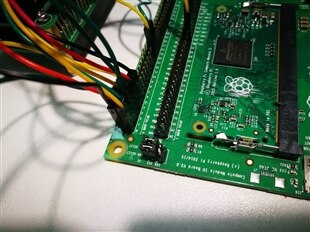
I2C has been set and enable correctly in /boot/config.txt and the raspbian version running on the eMMC of the CM3CM3 is the latest Jessie (July, 5 , 2017). Signals are connected to the GPIO2 and GPIO3 (SDA1, SCL1) accordingly with the eLinux table specifications (see in attach) to the GPIO Pins 2 and 3. Digilent device is powered with the 3V3 and voltage is correct and stable.

I have not used external pull-up resistors on SDA/SCL signals as the CM3 already includes 1.8K pull-up resistors on these two lines, following the CM3 peripheral recommendations.

imageimage

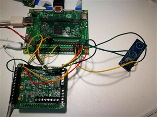
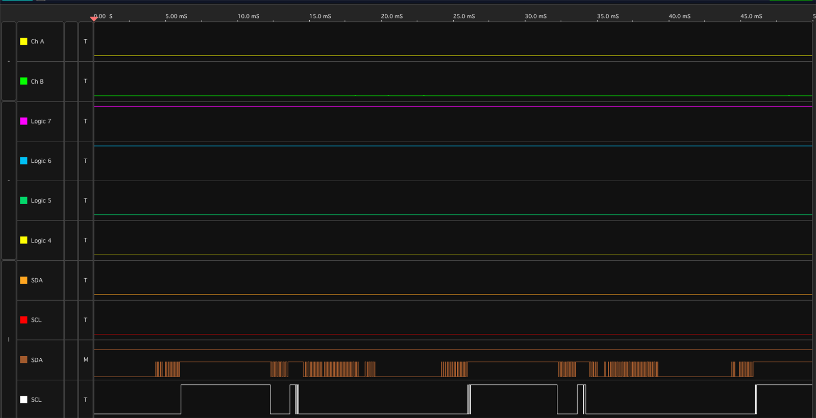
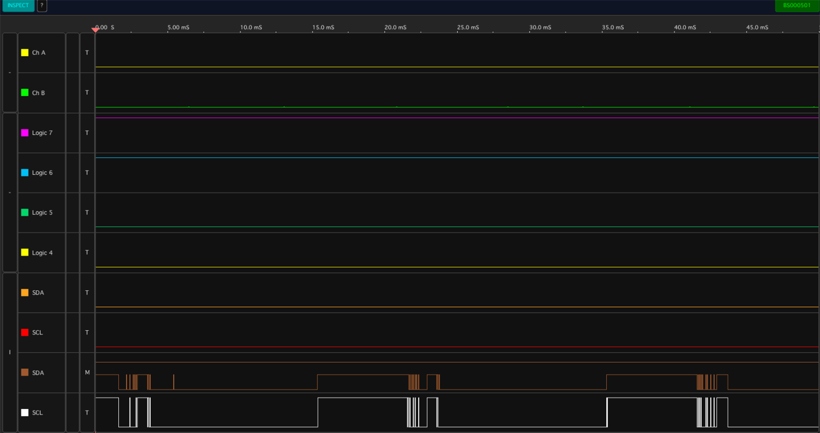
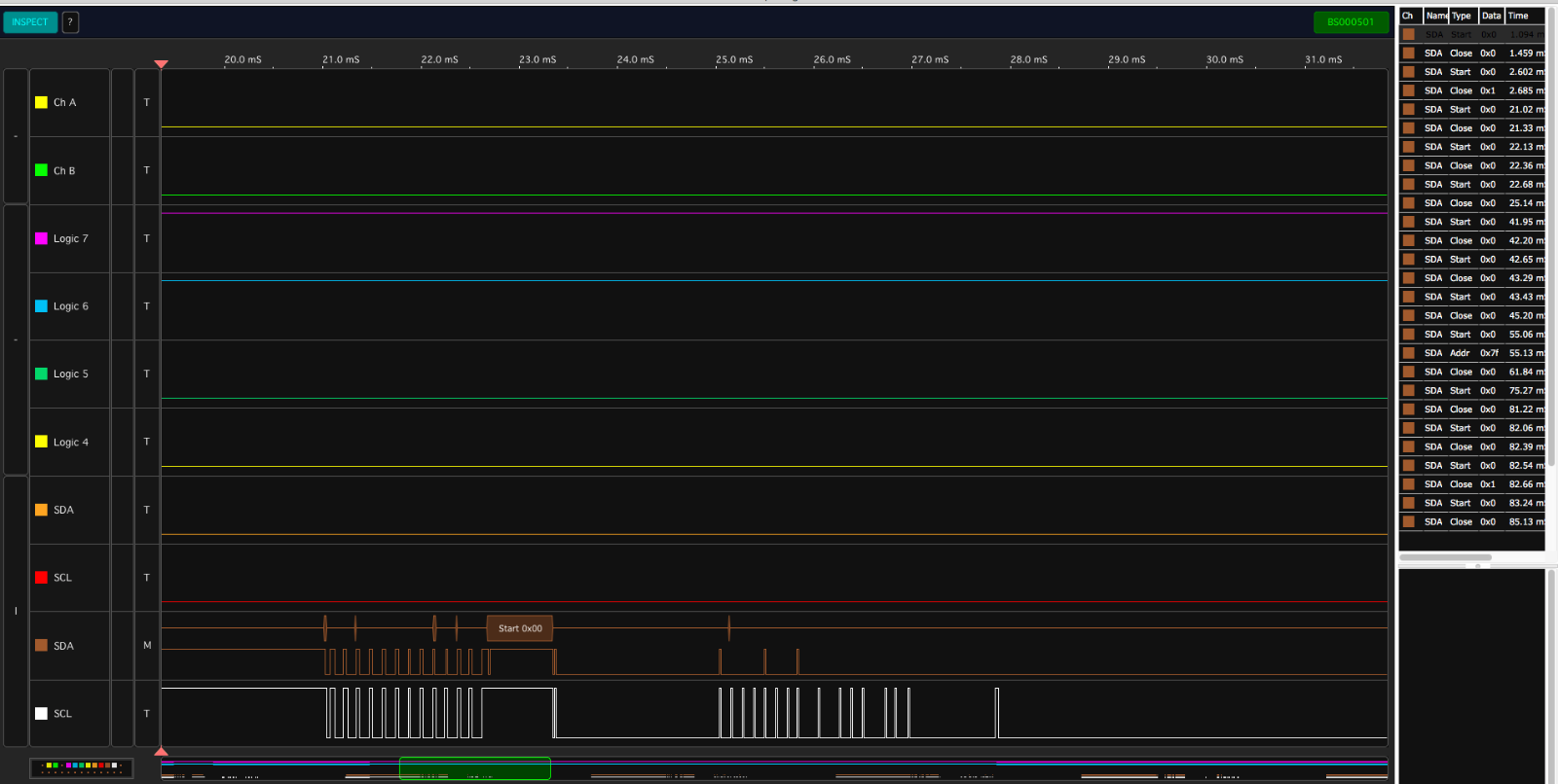
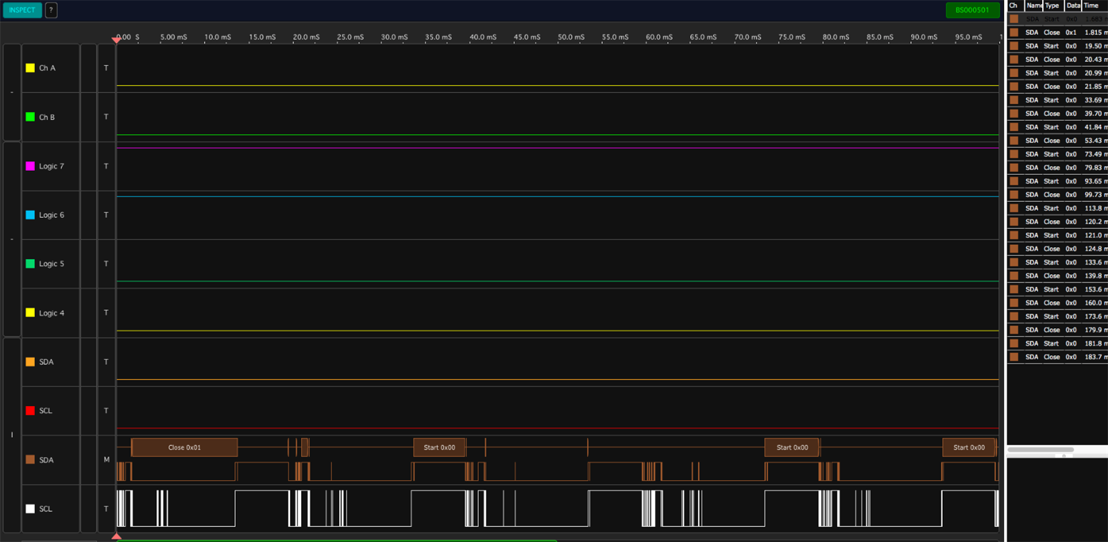
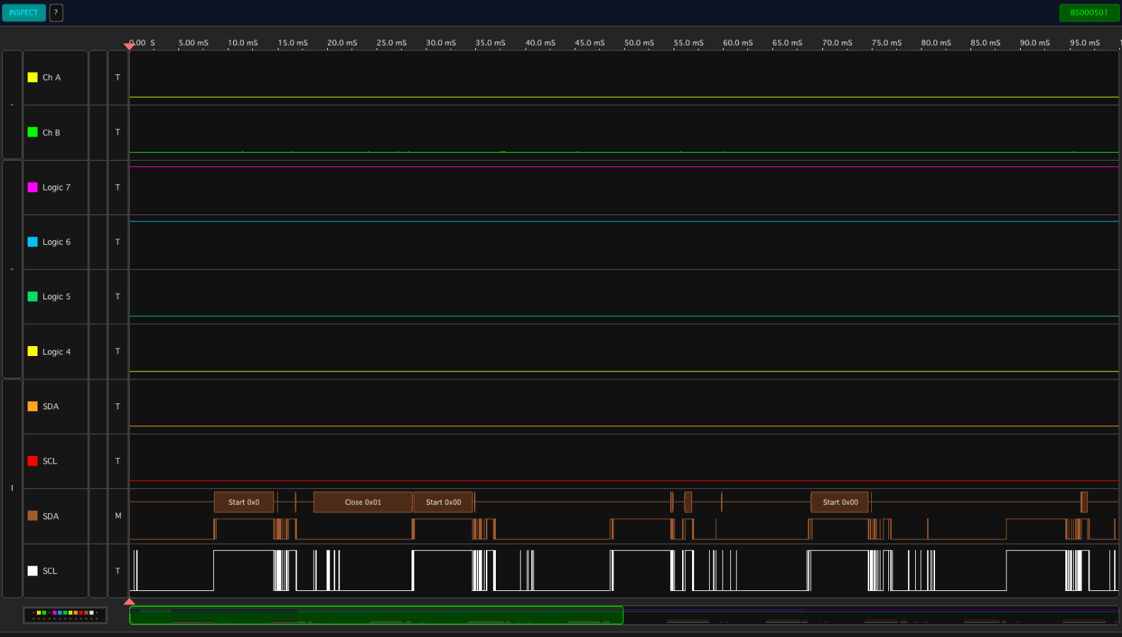
Initially I though that it was possible that wrong resistor values was blocking the signals to go up but as shown in the video below, hardware seems working fine. Note that when I send a i2cdetect -y 1 command from the terminal data are sent by the CM3 side. But nothing is shown.

Any suggestion is welcome.


You don't have permission to edit metadata of this video.
Edit media
x
image
Upload Preview
image


Update

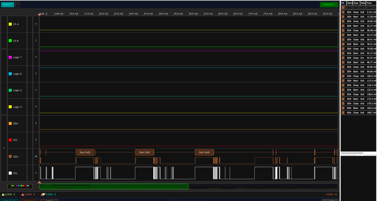
Supposing that despite what the documentation says the internal pull-up resistor is not enabled I have added a 1.5K resistor pulled up to the 3V3 (the nearest I have at home respect the declared in the documentation (1K8). What I get with the protocol analyser is a series of packets as shown in the images below but always nothing is detected by the master (Pi side).

image

image

image

image


Last update

After trying and discussing with all the helpful members that spent time with me I have received in the meantime a second Pi Compute Module IO board and as all the suggested tests and possible mistakes was converging to the right setup for the I2C protocol, as expected, the problem was for  some unknown reason the board itself. As I replaced the board with a new one things started working perfectly.


Thanks to shabaz Robert Peter Oakes rew Jan Cumps and... johnbeetem for the useless suggestion of the thread image LoL


Update

After the last testing and following some suggestions of the starting supposition is that - together with the I/O board - also the Compute Module 3 booting from the eMMC maybe with some hardware failure as all the tests with the Compute Module 3 Lite booting from the eMMC is working fine with the same Raspbian distribution, desktop version (instead of headless like on the eMMC side).


First test: a new microSD with the Raspbian Jessie Lite has been set and after booting the Compute Module 3 Lite I have done the same setup of the Compute Module eMMC. At this point bot boards runs the same version. And after sudo update / upgrade the command i2cdetect -y 1 works perfectly! So we can think 90% sure that the issue is in the Compute Module 3 with eMMC memory. Remain a last test to see if this issue is systematic or not: flashing another Compute Module 3 eMMC and see if it work.


Update - Conclusion

After doing the test mentioned in the update above a new Compute Module 3 eMMC board has been setup with a fresh installation and with the same connections of the previous settings, same Jessie Lite July 2017 and I2C protocol worked immediately without problems. So, the main issue was the CM3 eMMC board and the I/O board kit.

image


XMC1100 Boot Kit + TLE94112LE I2C communication

The setup of the two boards (XMC1100 + TLE94112LE) connected to the CM3 via the I2C bus was creating a trouble on the bus signals so that the i2cdetect -y 1 command was no longer able to recognise any connected peripheral.

The board has been configured as slave on the address 0x04. A check with the same software and the same hardware setup using and Arduino UNO instead was working fine. Investigating on this issue I have found the problem was already known involving Wire library version for the XMC1100 board updated by mhollfelder on the Infineon XMC1100 GitHub repository, the Pull Request #13.

On Aug, 31, 2017 Manuel (thanks) completed the update of the pull request, merged in the main and released a new XMC1100 Arduino board core  library version 1.0.4 (the module downloadable / upgradable in the Board Manager of the Arduino IDE) and all worked fine with the Infineon board alone connected to the I2C bus.


As I have integrated the XMC1100 Boot Kit board with the TLE94112LE DC Motor controller I have included the the TLE94112 Arduino library in the sketch detecting another non-blocking issue in the I2C Wire library (XMC1100 version) and opened the issue #14

The behaviour details are explained in the issue note; the problem can be easily avoided initialising the Wire library as the last call in the Setup() method of the sketch ;twe can consider this the workaround to the problem until it is not definitely solved.

Attachments:
imageRPi BCM2835 GPIOs - eLinux.pdf
imageRPI-CMIO-V3_0-SCHEMATIC.pdf
  • Sign in to reply
  • Cancel
  • shabaz
    shabaz over 8 years ago

    Hi Enrico,


    Interesting issue... I'm wondering if the pull-ups are not enabled, since it is a lengthy process to get them activated (edit device tree, recompile it, have it in the right place, reboot) and maybe they have not done it in the default image.

    I've never checked to see if the I2C pins have pull-ups by default on the normal Pi (not the compute module), I always add a couple of resistors (2.7k-ish is what I pick just for experimentation). I think it would be worth trying a value of around 2.7k-3.3k as external pull-ups, just to be 100% sure to rule this out. It won't cause any damage to try this resistance value.

    If that doesn't work, it may need a 'scope on the signals to see what could be happening : (


    With the Uno and XMC, there is a risk the I2C lines may have pull-ups to 5V and not 3.3V by the way (I don't know what I2C peripherals are on these boards, and if they already have pullups or not. If they don't have pull-ups then that's great.


    Apologies if you've already tried these things, this was just to be 100% sure.

    • Cancel
    • Vote Up +1 Vote Down
    • Sign in to reply
    • Cancel
  • balearicdynamics
    balearicdynamics over 8 years ago in reply to shabaz

    Hello Shabaz... ( image )


    I have checked just now the schematics of the board and as far as I know there are no external resistors inside. But yes, they can be compiled etc. I have read the documentation and it is not so difficult. The fact is that any update of the system the kernel modules are reset to their original default. And I am not so oriented to follow this way. Alternatively I am trying to place resistors externally. The worst case is that nothing change, so why not? I have tried at the moment with 1,5 K, 10K, 50K and 100K. No difference at all in the behaviour. For your information I will attach the board schematics, just to have 100% checked everything. Internal pull-up are not enabled (we can suppose) and there is not any setup in the schematics thinking to external resistors. But the documentation explicitly says that the GPIO pins have resistors enabled by default, 1.8 K

    The image below is the protocol analysis that shows always the same.

    image

    Do you have some idea about???


    I will attach the schematics to the original post. Enrico

    • Cancel
    • Vote Up 0 Vote Down
    • Sign in to reply
    • Cancel
  • johnbeetem
    johnbeetem over 8 years ago

    Did you check the RasPi schematics?  Ha, ha, just kidding image

    • Cancel
    • Vote Up +3 Vote Down
    • Sign in to reply
    • Cancel
  • balearicdynamics
    balearicdynamics over 8 years ago in reply to johnbeetem

    Anticipated you just few seconds John! See the attached documents image image image


    LoL

    • Cancel
    • Vote Up 0 Vote Down
    • Sign in to reply
    • Cancel
  • balearicdynamics
    balearicdynamics over 8 years ago in reply to johnbeetem

    Forgot to mention... Yes, the PI is powered on image

    • Cancel
    • Vote Up +1 Vote Down
    • Sign in to reply
    • Cancel
  • balearicdynamics
    balearicdynamics over 8 years ago in reply to shabaz

    Update. With a 1K resistor the signals on the two lines are aligned...


    image

    • Cancel
    • Vote Up 0 Vote Down
    • Sign in to reply
    • Cancel
  • shabaz
    shabaz over 8 years ago in reply to balearicdynamics

    Hi Enrico,


    Ahh very interesting. I guess it was just floating before, and getting approximately pulled up/down due to changes near it, and so it looked kind-of out-of-sync with the SDA pin. I think it will be worthwhile adding a resistor to the SDA pin too, if the SCL is floating then there is a risk that SDA is marginal too. They still look a bit weird but maybe that is just the display, if you can zoom into a single packet that will be good.

    • Cancel
    • Vote Up +1 Vote Down
    • Sign in to reply
    • Cancel
  • balearicdynamics
    balearicdynamics over 8 years ago in reply to shabaz

    Thank you for the suggestion Shabaz. I put a last update on the original post then I will do tomorrow morning for first. Thank you a lot for now image, here it is 2 a.m. image image image


    BTW: I put always two resistors on both the signals, as it is expected by the bus.


    Enrico

    • Cancel
    • Vote Up +1 Vote Down
    • Sign in to reply
    • Cancel
  • balearicdynamics
    balearicdynamics over 8 years ago in reply to shabaz

    It is the packet running now. To the right the data dequence of the packets (mostly start/close)


    Enrico


    image

    • Cancel
    • Vote Up +1 Vote Down
    • Sign in to reply
    • Cancel
  • Robert Peter Oakes
    Robert Peter Oakes over 8 years ago in reply to shabaz

    I would agree, with I2C it is an open collector type bus (Open Source in the case of a FET image ), either way, both SCL and SDA need pullup resistors, any value between 1 and 10K will normally work with a small distance and device count, your value of 1.5K or close to that is ok.


    I have also found with the scope you need to set the trigger levels correctly too.

    the fact you're only seeing 00 all the time or most of it, is a little concerning though

    • Cancel
    • Vote Up +1 Vote Down
    • Sign in to reply
    • Cancel
>
element14 Community

element14 is the first online community specifically for engineers. Connect with your peers and get expert answers to your questions.

  • Members
  • Learn
  • Technologies
  • Challenges & Projects
  • Products
  • Store
  • About Us
  • Feedback & Support
  • FAQs
  • Terms of Use
  • Privacy Policy
  • Legal and Copyright Notices
  • Sitemap
  • Cookies

An Avnet Company © 2025 Premier Farnell Limited. All Rights Reserved.

Premier Farnell Ltd, registered in England and Wales (no 00876412), registered office: Farnell House, Forge Lane, Leeds LS12 2NE.

ICP 备案号 10220084.

Follow element14

  • X
  • Facebook
  • linkedin
  • YouTube