


Hi All! Let's continue the Road Test of the Aim-TTi SMU4201 Source Measure Unit (SMU)! 
Previous blog posts:
Aim-TTi SMU4201 Road Test | Unboxing, First Look and User Interface
1. Specifications
First, lets take a look on some values from the specification of the Aim-TTi SMU4201 source measure unit:
| Feature |
Ranges |
Resolution |
Accuracy |
|
Voltage Measurement |
|
10nV |
±0.06%rdg ± 50µV |
|
Current |
|
100fA |
±0.04%rdg ± 300pA |
Voltage Source (SV and MHR modes) |
±21V |
210V/s |
Same as voltage |
| Current Source or Load (SC, LC, LR, LP and MR modes) |
±3.15A |
3A/s to 36mA/µs 25W/s to LP mode 0.25W/µs |
Same as current |
The specifications of the SMU4201 are really impressive. The measurement accuracy is about two orders of magnitude (100x) better compared to a handheld DMM. On the voltage / current sourcing and sinking side it meets the specification of a precision laboratory power supplies and electronic loads.
As far I can see the specification are on par with other SMU from the market. The more detailed comparison with competitors will also come in my final review.
Now let's try out some of the functionality offered by the instrument!
2. Experiments
The Aim-TTi QPX750SP is a 750W switching mode power supply I Road Test-ed in 2021. Back then, I compared several power supply units, including lab power supplies, power bricks and batteries. In this blog post I wanted to replicate some of the experiments with the Aim-TTi SMU4201 source measure unit, along with a set of experiments focusing the current sinking and measuring capabilities of the instrument.
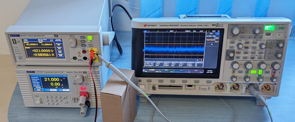
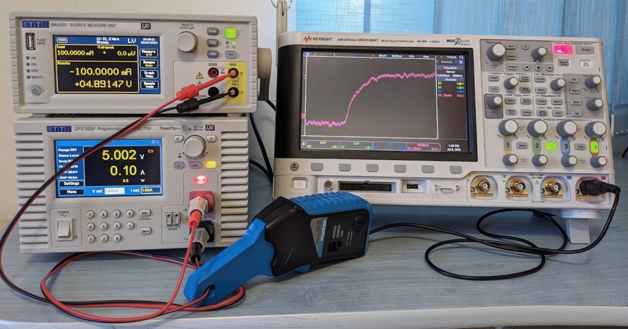
The instruments used in this experiment are the Aim-TTI SMU4201, the Aim-TTi QPX750SP and the Keysight MSOX3034T oscilloscope.
2.1. Power Supply Experiments
In this first section we will test the behaviour of the two instruments when loaded with resistive, capacitive and inductive loads.
Resistive Loads
Most of the devices used in hobby electronics can be considered resistive loads, so I thought to put accent on this type of load.
The resistive loads used are floor heating sheet and various heating elements extracted from broken household appliances. Their resistance value with the current and power value at the tested voltages are shown in the table bellow:
|
Voltage (V) |
Resistance (Ω) Current (A) | Power (W) |
|||||||
|
4.20 Ω
|
|
36.00 Ω
|
93.00 Ω
|
|||||
| 3.3 | 0.79 | 2.59 | ― | ― | ― | ― | ― | ― |
| 5 | 1.19 | 5.95 | ― | ― | ― | ― | ― | ― |
| 10 | 2.38 | 23.81 | 0.53 | 5.26 | ― | ― | ― | ― |
| 21 | ― | ― | 1.11 | 23.21 | 0.58 | 12.25 | ― | ― |
| 42 | ― | ― | ― | ― | ― | ― | 0.45 | 18.87 |


Note: the test voltages values were chosen to mostly cover the 25W power envelope of the SMU4201.
Using the oscilloscope the noise / ripple values along with the rise and fall times during turn on and turn off actions were captured:
|
Resistive Loads |
Aim-TTi |
Aim-TTi
|
Waveforms |
|||
|
Noise |
Turn |
Noise rms | p-p (mV) |
Turn On / Off Times (ms) |
|||
|
3.3 V |
4.2 Ω |
1.37 |
~3.0 |
2.52 |
~150 |
SMU4201 |
|
5 V |
4.2 Ω |
1.33 |
~4.0 |
1.33 ― 13.35 |
~200 ― ~350 |
SMU4201 |
|
10 V |
4.2 Ω |
1.34 |
~3.5 |
1.26 |
~150 |
SMU4201 |
| 19 Ω |
1.55 |
~2.5 |
1.10 ― 10.00 |
~150 ― ~150 |
SMU4201 |
|
|
21 V |
19 Ω |
1.85 |
~2.0 |
1.10 ― 10.00 |
~200 ― ~150 |
SMU4201 |
| 36 Ω |
1.84 |
~1.5 |
1.32 ― 13.36 |
~175 ― ~200 |
SMU4201 |
|
|
42 V |
93 Ω |
2.37 |
~2.0 |
1.33 ― 13.61 |
~150 ― ~175 |
SMU4201 |


Note: the measures values were captured at the output terminal of the power supplies. However the test setup was far from perfect, so some noise is expected in the measured values.
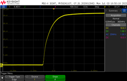
As we can see both the SMU4201 and QPX750SP handles restive load excellently. The RMS noise / ripple is around ~1.0-2.5mV (including measurement noise) with peak-to-peak values under 40mV, with higher for the SMU4201. With the default settings the SMU4201 has much more aggressive turn on and off times (<5ms) compared to the QPX750SP (~200ms).
Negative voltages
The SMU4201 contrary to the QPX750SP can also supply negative voltages. I tested this at 21V with a 36Ω load:
| Resistive Loads |
Aim-TTi |
Aim-TTi
|
Waveforms |
|||
|
Noise |
Turn |
Noise rms | p-p (mV) |
Turn On / Off Times (ms) |
|||
|
21 V |
36 Ω |
3.33 |
~2.5 |
― |
― |
SMU4201 |


The measured values are similar to the ones obtained with positive voltages.
Capacitive Loads
Next, I wanted to try out some capacitive loads. What I used is five of 470 µF electrolytic capacitors connected in parallel:
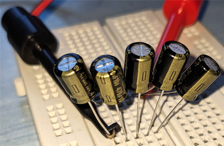
The capacitors were tested at 5V with a current limit of 1.5A.
Note: the default OFF State Mode of the SMU4201 is 0V/100µA, and with this settings it takes "forever" to discharge this capacitors at turn off. For this reason I decided to set the OFF State Mode to ZERO, with the current limit configured above.
|
Capacitive Load |
Aim-TTi |
Aim-TTi
|
Waveforms |
|||
|
Noise |
Turn |
Noise rms | p-p (mV) |
Turn On / Off Times (ms) |
|||
|
5 V |
5 x 470 µF |
1.17 |
~120 |
1.09 |
~200 |
SMU4201 |


Both the SMU4201 and the QPX750SP showed very low noise, with slightly lower turn on and off times for the SMU. In the case of the SMU there are some overshoots visible at turn on and off, probably caused by the aggressive slew rate settings.
Inductive Loads
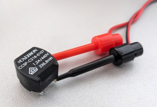
As the last step I wanted to try out some inductive loads. First I wanted to use a 12V brushed DC motor, but because of the high inrush current and switching node, I gave up on that idea. Instead, I used one half of a common mode choke, which is basically an inductor of 6.8 mH:
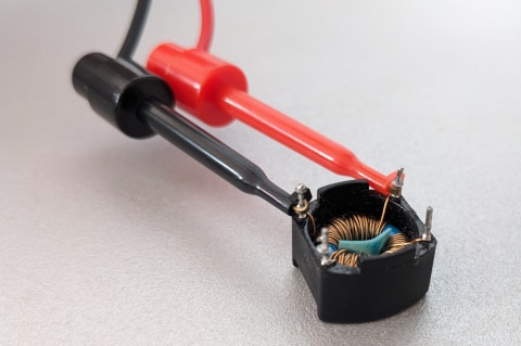
The tests were done @ 1V with a current limit of 1.5A. In the inductor this caused an initial current spike, after which the current settled at around 0.7-0.9A.
| Capacitive Load |
Aim-TTi |
Aim-TTi
|
Waveforms |
|||
|
Noise |
Turn |
Noise rms | p-p (mV) |
Turn On / Off Times (ms) |
|||
|
1 V |
6.8 mH |
1.39 |
~100? |
37.24 |
~50 |
SMU4201
|


I must say the two power supply supplies did not liked my inductive load. 
First on the SMU4201 the over power protection (OPP) was tripped, so I needed to activate the High Reactance mode, and set the Slew Rate to the minimum value of 210V/s. Then sometimes the instrument and the inductor entered some resonance mode causing ~50V ripple.
Overshoots were present both with the SMU4201 and QPX750SP. When the setup stabilized the SMU managed to maintain a significantly lower noise level.
2.2 Electronic Load Experiments
A source measure unit (SMU) can both source and sink current. To test this capability of the SMU4201, the instrument was configured as an electronic load, while the QPX750SP acted as the power source.
The SMU4201 has 3 main Sink modes: load current (LC), load resistance (LR) and load power (LP). I tested the turn on and off behaviour of each mode, as well as switching between two load values.
Instead of measuring voltage, in these experiment I used a the Hantek CC-65 current clamp probe to take a look on the current waveforms produces by intrument.
|
Load Current |
Aim-TTi |
Waveforms |
|
|
5 V |
-100 mA |
Turn On / Off
|
SMU4201 |


|
Load Resistance |
Aim-TTi |
Waveforms |
|
|
5 V |
20 Ω |
Turn On / Off
|
SMU4201 |


|
Load Power |
Aim-TTi |
Waveforms |
|
|
5 V |
2 W |
Turn On / Off
|
SMU4201
|


The produced waveform are clear, and does not contain any glitches. The turn on and off times, and well the load switching times of the SMU4201 are around 0.15 - 0.30 ms.
Sinking with negative voltages
The SMU4201 is a four quadrant instrument, so along sinking negative (-) currents from positive (+) voltage sources (quadrant Q4), it should also be able to sink positive currents (+) from negative (-) voltage sources (quadrant Q2).
For some weird reason the Load operation modes (CC, CR, CP) can only be used with positive (+) voltages and therefore negative (-) currents. To sink current from negative (-) voltages, we must use one of the source voltage or current mode.
I managed to get it working in Source Voltage (SV) mode with setting a negative source voltage near zero (-0.5V) with the desired current limit applied in both polarities (+/-). Because I was a bit afraid I will accidentally apply negative voltages to the output of the QPX750SP, I decided to do the negative voltage sink test with a 1.5V AAA battery.
|
Constant Current |
Aim-TTi |
Waveforms |
|
|
-1.5 V |
+100 mA |
Turn On / Off
|
SMU4201 |


2.3. Measuring a Zero-Ohm Link
Along souring and sinking current, the SMU4201 can also be used as a 6½ digit resolution multimeter. It can measure voltages, currents and resistances and has support for 4-wire measurements.
To demonstrate the measurement capability of the instrument, I choose to do a 4-wire resistance measurements of a "zero-ohm link":
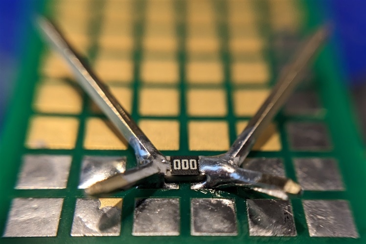
A "zero-ohm link" is a resistor with a nominal 0 Ω value, and it is used for various purposes. In reality, according to Wikipedia the resistor will have a resistance of around 10-50 mΩ, so it is a great way to demonstrate the 4-wire measurement technique.
The purpose of 4-wire measurement techniques is to eliminate the measurement errors resulting from the contact and lead resistances of the test leads. With 4-wire measurement we are using 2 wires dedicated to passing the test current, and an another two to measure voltage.
For this test I used a random SMD 0805 package "zero-ohm link" soldered to prototype board, along some right angle pin headers on each side. This setup allows connecting 4 test clips, 2 on side of the resistor.
The SMU4201 was set up for resistance measurements first in 2-wire, then in 4-wire mode. The test current used was 100 mA.
Using the 2-wire mode the measure resistance was 794 mΩ, it was really unstable and I even needed temporarily apply 1A test current to somewhat stabilize the measurement.

Switching to the 4-wire measurement technique immediately showed the real 17.20 mΩ value value of the resistor:

and the measurement remained stable.
In the next weeks, I will get into the programming / remote control side of the instrument. This will include among others automated experiments with low power wireless devices, battery characterization and simulation.
Hope you enjoyed this update!
Top Comments