element14 Community
element14 Community
    Register Log In
  • Site
  • Search
  • Log In Register
  • Community Hub
    Community Hub
    • What's New on element14
    • Feedback and Support
    • Benefits of Membership
    • Personal Blogs
    • Members Area
    • Achievement Levels
  • Learn
    Learn
    • Ask an Expert
    • eBooks
    • element14 presents
    • Learning Center
    • Tech Spotlight
    • STEM Academy
    • Webinars, Training and Events
    • Learning Groups
  • Technologies
    Technologies
    • 3D Printing
    • FPGA
    • Industrial Automation
    • Internet of Things
    • Power & Energy
    • Sensors
    • Technology Groups
  • Challenges & Projects
    Challenges & Projects
    • Design Challenges
    • element14 presents Projects
    • Project14
    • Arduino Projects
    • Raspberry Pi Projects
    • Project Groups
  • Products & Partners
    Products & Partners
    • Arduino
    • Avnet & Tria Boards Community
    • Dev Tools
    • Manufacturers
    • Multicomp Pro
    • Product Groups
    • Raspberry Pi
    • RoadTests & Reviews
  • About Us
    About the element14 Community
  • Store
    Store
    • Visit Your Store
    • Choose another store...
      • Europe
      •  Austria (German)
      •  Belgium (Dutch, French)
      •  Bulgaria (Bulgarian)
      •  Czech Republic (Czech)
      •  Denmark (Danish)
      •  Estonia (Estonian)
      •  Finland (Finnish)
      •  France (French)
      •  Germany (German)
      •  Hungary (Hungarian)
      •  Ireland
      •  Israel
      •  Italy (Italian)
      •  Latvia (Latvian)
      •  
      •  Lithuania (Lithuanian)
      •  Netherlands (Dutch)
      •  Norway (Norwegian)
      •  Poland (Polish)
      •  Portugal (Portuguese)
      •  Romania (Romanian)
      •  Russia (Russian)
      •  Slovakia (Slovak)
      •  Slovenia (Slovenian)
      •  Spain (Spanish)
      •  Sweden (Swedish)
      •  Switzerland(German, French)
      •  Turkey (Turkish)
      •  United Kingdom
      • Asia Pacific
      •  Australia
      •  China
      •  Hong Kong
      •  India
      •  Japan
      •  Korea (Korean)
      •  Malaysia
      •  New Zealand
      •  Philippines
      •  Singapore
      •  Taiwan
      •  Thailand (Thai)
      •  Vietnam
      • Americas
      •  Brazil (Portuguese)
      •  Canada
      •  Mexico (Spanish)
      •  United States
      Can't find the country/region you're looking for? Visit our export site or find a local distributor.
  • Translate
  • Profile
  • Settings
RoadTests & Reviews
  • Products & Partners
  • More
RoadTests & Reviews
Review Blogs Blog 3 – Oscilloscope application in the Red Pitaya STEMlab 125-14 PRO Gen 2
  • Blogs
  • Forum
  • Documents
  • RoadTests
  • Reviews
  • Polls
  • Files
  • Members
  • Sub-Groups
  • More
  • Cancel
  • New
Join RoadTests & Reviews to participate - click to join for free!
  • Share
  • More
  • Cancel
  • Author Author: obones
  • Date Created: 28 Oct 2026 3:39 PM Date Created
  • Views 91 views
  • Likes 6 likes
  • Comments 5 comments
Related
Recommended
  • RoadTest
  • red pitaya

Blog 3 – Oscilloscope application in the Red Pitaya STEMlab 125-14 PRO Gen 2

obones
obones
28 Oct 2026

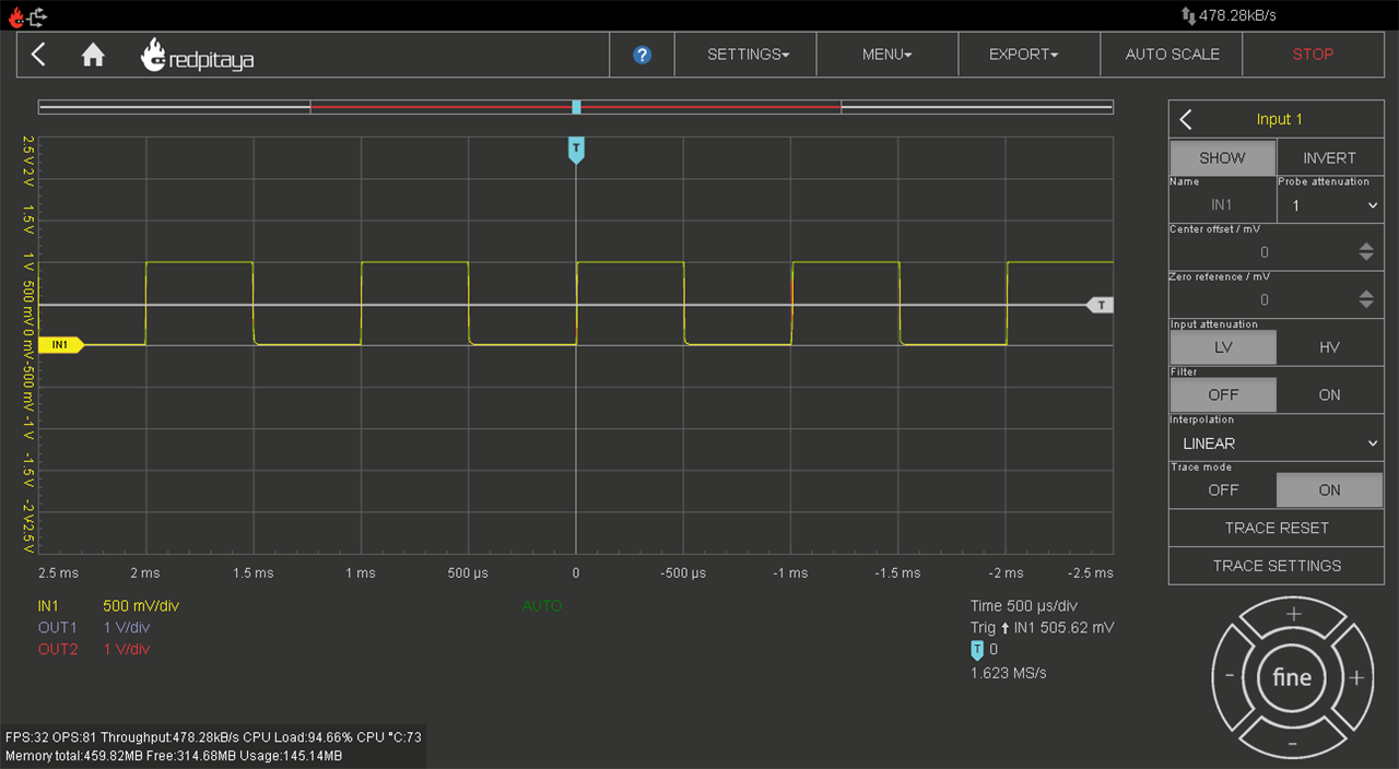
One of the easiest way to exercise the analog frontend of the Red Pitaya STEMlab 125-14 PRO Gen 2 is by feeding it a known signal and see how it is perceived. For this,t he oscilloscope app is the best candidate.

After starting the app, I plugged the probes to the 1kHz 5V reference signal for probe compensation on the MP720012 that I have on my bench. I was expecting to see this:
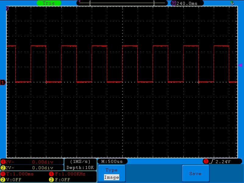
image

Instead, I got this:

image

The manual says this:

Red Pitaya boards are factory-calibrated before shipping and should provide accurate measurements immediately after purchase.

But clearly, this is not what I’m seeing here with range being clipped, so I decided to go through the whole calibration process:
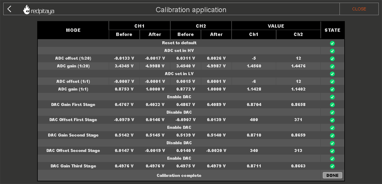
image

Values were a bit off, but after that, nothing changed on the oscilloscope!

After a bit of search, I found a clue in the forums: https://forum.redpitaya.com/viewtopic.php?t=1128

And with the proper “jumper” search term, one can finally find the information in the documentation, deep down in the developer’s guide hardware section: https://redpitaya.readthedocs.io/en/latest/developerGuide/hardware/GEN2/hw_specs/hw_specs.html#jumper-settings

So, by default, the input stage crops out anything outside -1/+1V and one has to move a pair of jumpers to the HV position to get -20/+20V. But the application guide for the oscilloscope does not mention this in any clear way, nor does it mention the absolute voltage value which is found in yet another page: https://redpitaya.readthedocs.io/en/latest/developerGuide/hardware/GEN2/125-14_Gen2_Pro/top.html#technical-specifications

This means that I could have “fried” the board with giving it what I thought is a perfectly innocuous test signal. A warning on the oscilloscope documentation page is more than required.

The jumpers have an orientation, that’s a first for me and quite a surprise. And clearly, what’s mentioned in the documentation about trace impact is right:

Incorrect jumper placement can cause the front part of acquired square wave signals to be overshot or undercut.

I did not find this early one and spent quite a while turning the probe adjustment knob, to no avail.

But really, it’s totally inconvenient to have those jumpers, they are VERY tiny, difficult to take out, and prone to land on all the components on the PCB. A regular jumper would not be a danger, but with the metallic part flush at the bottom, there is a risk of making contact with something on the board.
And we can’t really turn off the board while changing their position because the calibration process would then start over after reboot.

Also, it is mentioned that both jumpers should be on the same side of the connector. Well, it would be much easier if they were “glued” together, thus preventing the user from even being able to create a forbidden configuration with undocumented consequences.

For ease of manipulation, they also should have a “long tail” or replaced altogether by a DIP style two-way switch. Sure, it may take more board room and require a toothpick to manipulate, but at least, it won’t jump out of my desk and require me to spend a good 5 minutes to finally find it between the floor and the desk leg.


This blog is part of 7-part series for my Red Pitaya STEMlab 125-14 PRO Gen 2 Starter Kit roadtest:

Blog 1 – Unboxing the Red Pitaya STEMlab 125-14 PRO Gen 2 Starter Kit
Blog 2 – First contact with the Red Pitaya STEMlab 125-14 PRO Gen 2
Blog 3 – Oscilloscope application in the Red Pitaya STEMlab 125-14 PRO Gen 2
Blog 4 – Logic analyzer application in the Red Pitaya STEMlab 125-14 PRO Gen 2
Blog 5 – Software defined radio with the Red Pitaya STEMlab 125-14 PRO Gen 2
Blog 6 – Developing for the Red Pitaya STEMlab 125-14 PRO Gen 2
Red Pitaya STEMlab 125-14 PRO Gen 2 roadtest report

  • Sign in to reply
  • obones
    obones 4 days ago in reply to jc2048

    Well, no, I don't look at schematics first, especially when the documentation website says this:

    Full hardware schematics for the Red Pitaya board are not available. Red Pitaya has open-source code but not open hardware schematics. Nonetheless, development schematics are available. This schematic will give you information about hardware configuration, FPGA pin connections, and similar.

    So, thanks for pointing out the absence of risk in creating the forbidden pin configuration, but I must insist, the documentation page for the oscilloscope application should really mention that.

    • Cancel
    • Vote Up 0 Vote Down
    • Sign in to reply
    • More
    • Cancel
  • jc2048
    jc2048 4 days ago in reply to obones

    The only document I looked at was the schematic. Doesn't everyone look at the schematic first?

    image

    If I've got the right one (there are a lot of variants of this board, aren't there?), the front end of this one looks like it's intended to be used with conventional 'scope probes.

    Rin is 1M, and it looks like the capacitors have been chosen so that the input capacitance would fall within the adjustment range of a x10 probe. Worth a try, unless you need the sensitivity that the x1 gives you. Any old x10 probe is almost certain to give you the full 60MHz bandwidth, whereas x1 may not.

    Since the two paths are just passive attenuators, getting the links wrong won't hurt - you'll just wonder why you aren't seeing a signal.

    • Cancel
    • Vote Up 0 Vote Down
    • Sign in to reply
    • More
    • Cancel
  • obones
    obones 5 days ago in reply to jc2048

    Most surely yes, but it's totally not intuitive here, and no such suggestion is given in the documentation anyway

    • Cancel
    • Vote Up 0 Vote Down
    • Sign in to reply
    • More
    • Cancel
  • jc2048
    jc2048 5 days ago

    Couldn't you have used a x10 probe to give a -10V to +10V input range?

    • Cancel
    • Vote Up 0 Vote Down
    • Sign in to reply
    • More
    • Cancel
  • DAB
    DAB 5 days ago

    From everyone's descriptions, you definitely need to fully read the documentation before working with this device.

    • Cancel
    • Vote Up 0 Vote Down
    • Sign in to reply
    • More
    • Cancel
element14 Community

element14 is the first online community specifically for engineers. Connect with your peers and get expert answers to your questions.

  • Members
  • Learn
  • Technologies
  • Challenges & Projects
  • Products
  • Store
  • About Us
  • Feedback & Support
  • FAQs
  • Terms of Use
  • Privacy Policy
  • Legal and Copyright Notices
  • Sitemap
  • Cookies

An Avnet Company © 2026 Premier Farnell Limited. All Rights Reserved.

Premier Farnell Ltd, registered in England and Wales (no 00876412), registered office: Farnell House, Forge Lane, Leeds LS12 2NE.

Follow element14

  • X
  • Facebook
  • linkedin
  • YouTube