


In my application for this roadtest, I mentioned using the RedPitaya Logic Analyzer app on a blind remote that I have here: the MCU talks to a ATMEL 25010 EEPROM and a CC1070 transmitter chip, all on a 2.7V logic which is within range of the RedPitaya board.
One can use the logic analyzer app directly, but it is recommended to get the extension module (80€), to get larger voltage scale and protect the input pins. That’s very surprising that for the base price the inputs are not overvoltage protected and/or 5V tolerant.
That module comes as a large block with a metal case, that sits on top of the RedPitaya by connecting to the E1 and E2 connectors, reminiscent of the PATA hard drive connectors of the day.
It is very strange that the female connectors on the extension are not keyed when the mating ones clearly expect them. This means that there is nothing preventing me from putting it in reverse or even shifted by one pin, with potentially disastrous consequences.
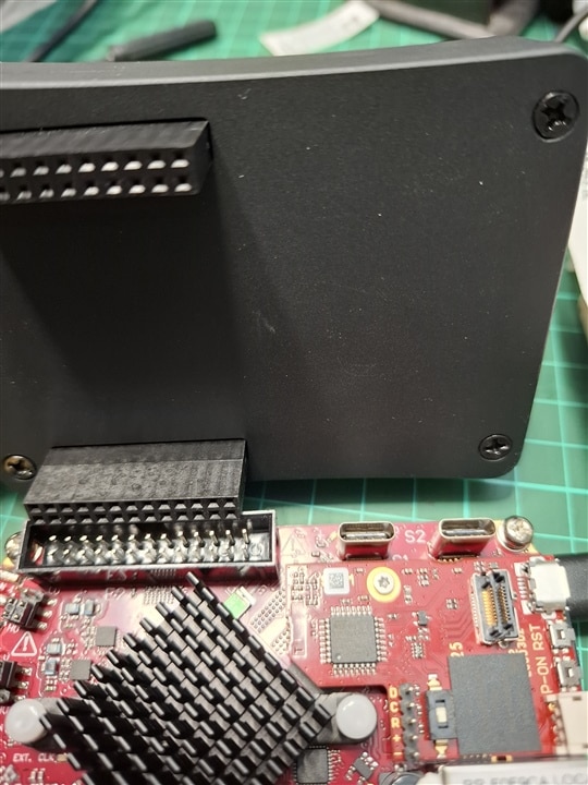
Out of curiosity, I took the extension apart to see what’s inside it that could justify the price tag:
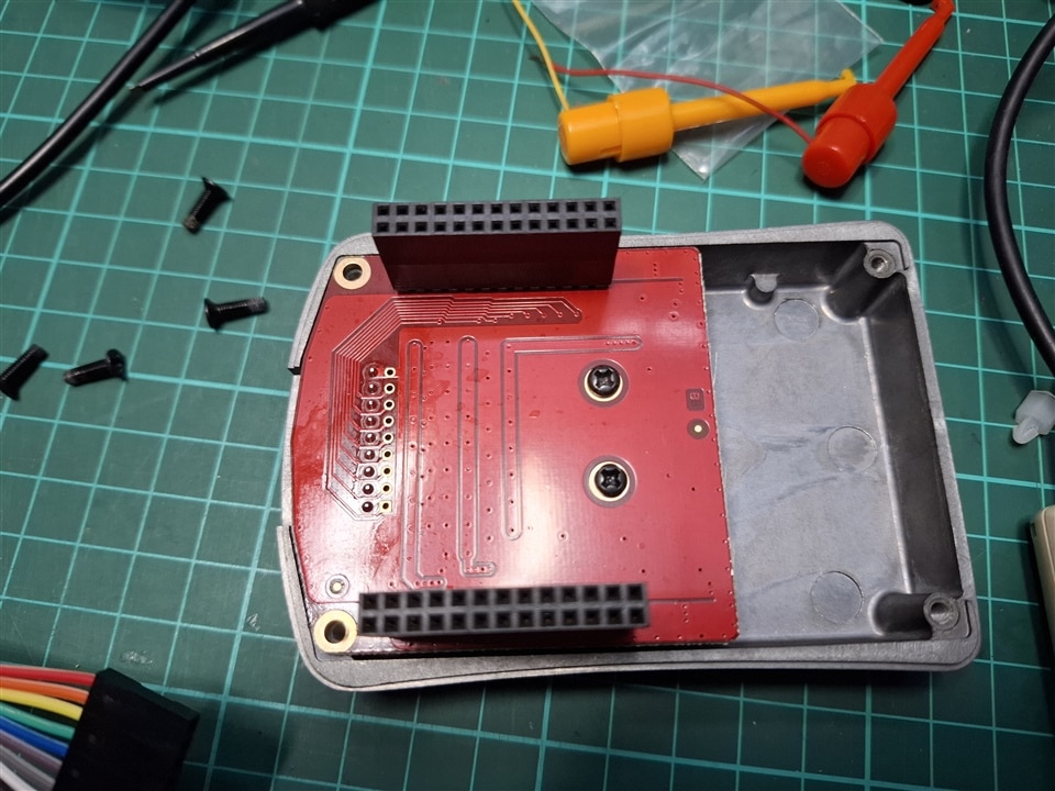
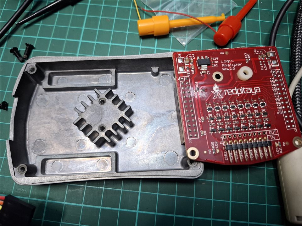
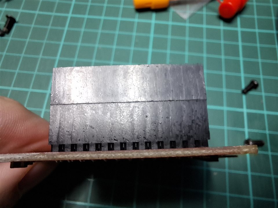
Those of you who read colporteur blog posts may feel that the case is somewhat similar to a picture they already saw.
As expected, it’s a large collection of transistors that “protect” the main board in case of overvoltage. Interestingly enough, there is an “out” row for the connector that is not populated and leads to resistors that are also missing. Maybe there was a “transmit” mode in the initial design but that never made it to the final product.
The provided probe cable needs some assembly, very tedious. Remember to slide back the white marker sleeves to be able to connect to the probe ends. The moving pin and the solder “bubble” do not give great confidence as to the quality of the connection.
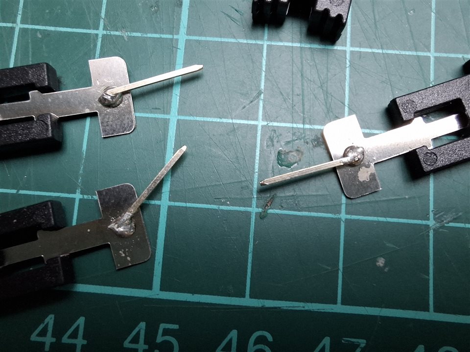
The “grips” are not strong and slide off regular pins at the lightest touch which makes its very difficult to setup considering the ribbon is quite stiff as well.
This led me to use different hooks but ended up as a spaghetti bowl that I find ugly. Note that this on an ESP32 + RFM69 setup that I know is working, so that I can test the analysis of known signals before moving to inspecting an entirely unknown situation.
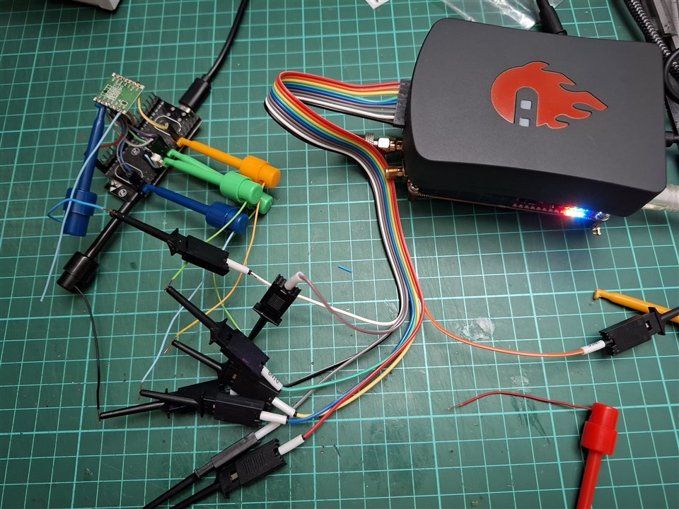
Sadly, after careful selection of parameters, while the application sees the signals, for some reason it does not analyze the bus at all. I asked about that situation in the forum and got suggested to use a not yet released “beta” version which means replacing the entire SD card content. And it’s not even a simple image to write with balenaEtcher, but rather a convoluted process that at some point even involves overwriting individual files in the right place…
What I wanted to do next was to export the read samples to a format that PulseView can read, but I couldn’t find a way to do that. The documentation says there is a “File” option in the export menu. And frankly, exporting to a WAV file would be nice as PulseView can import it just fine. But despite what the documentation is saying, it’s not there!
There is a “version” selector panel at the bottom right of the documentation page, but there is only one version available, so I can’t know if it’s something that was there and got removed, or something that will come up in a later version of the OS.
There should really be a history of documentation here to match whichever OS version a user is using To get a good example of such a version documentation, you can head over to to Terraform or NodeJS documentation websites.
A direct driver for PulseView would allow reading for longer time periods, but this too seems to be missing. This was talked about in this blog: https://content.redpitaya.com/blog/logic-analyzer-shield-for-a-rp-board
But this does not seem to have made it to the final product, there are no traces of the SUMP protocol in the documentation nor in the code.
For the kind of price the extension put me at, I really feel I should have gone with a BusPirate which does advertise about PulseView support.
So right now, I’m stuck on not being able to achieve one of the objectives of my application…
This blog is part of 7-part series for my Red Pitaya STEMlab 125-14 PRO Gen 2 Starter Kit roadtest:
Blog 1 – Unboxing the Red Pitaya STEMlab 125-14 PRO Gen 2 Starter Kit
Blog 2 – First contact with the Red Pitaya STEMlab 125-14 PRO Gen 2
Blog 3 – Oscilloscope application in the Red Pitaya STEMlab 125-14 PRO Gen 2
Blog 4 – Logic analyzer application in the Red Pitaya STEMlab 125-14 PRO Gen 2
Blog 5 – Software defined radio with the Red Pitaya STEMlab 125-14 PRO Gen 2
Blog 6 – Developing for the Red Pitaya STEMlab 125-14 PRO Gen 2
Red Pitaya STEMlab 125-14 PRO Gen 2 roadtest report


