element14 Community
element14 Community
    Register Log In
  • Site
  • Search
  • Log In Register
  • Community Hub
    Community Hub
    • What's New on element14
    • Feedback and Support
    • Benefits of Membership
    • Personal Blogs
    • Members Area
    • Achievement Levels
  • Learn
    Learn
    • Ask an Expert
    • eBooks
    • element14 presents
    • Learning Center
    • Tech Spotlight
    • STEM Academy
    • Webinars, Training and Events
    • Learning Groups
  • Technologies
    Technologies
    • 3D Printing
    • FPGA
    • Industrial Automation
    • Internet of Things
    • Power & Energy
    • Sensors
    • Technology Groups
  • Challenges & Projects
    Challenges & Projects
    • Design Challenges
    • element14 presents Projects
    • Project14
    • Arduino Projects
    • Raspberry Pi Projects
    • Project Groups
  • Products & Partners
    Products & Partners
    • Arduino
    • Avnet & Tria Boards Community
    • Dev Tools
    • Manufacturers
    • Multicomp Pro
    • Product Groups
    • Raspberry Pi
    • RoadTests & Reviews
  • About Us
    About the element14 Community
  • Store
    Store
    • Visit Your Store
    • Choose another store...
      • Europe
      •  Austria (German)
      •  Belgium (Dutch, French)
      •  Bulgaria (Bulgarian)
      •  Czech Republic (Czech)
      •  Denmark (Danish)
      •  Estonia (Estonian)
      •  Finland (Finnish)
      •  France (French)
      •  Germany (German)
      •  Hungary (Hungarian)
      •  Ireland
      •  Israel
      •  Italy (Italian)
      •  Latvia (Latvian)
      •  
      •  Lithuania (Lithuanian)
      •  Netherlands (Dutch)
      •  Norway (Norwegian)
      •  Poland (Polish)
      •  Portugal (Portuguese)
      •  Romania (Romanian)
      •  Russia (Russian)
      •  Slovakia (Slovak)
      •  Slovenia (Slovenian)
      •  Spain (Spanish)
      •  Sweden (Swedish)
      •  Switzerland(German, French)
      •  Turkey (Turkish)
      •  United Kingdom
      • Asia Pacific
      •  Australia
      •  China
      •  Hong Kong
      •  India
      •  Japan
      •  Korea (Korean)
      •  Malaysia
      •  New Zealand
      •  Philippines
      •  Singapore
      •  Taiwan
      •  Thailand (Thai)
      •  Vietnam
      • Americas
      •  Brazil (Portuguese)
      •  Canada
      •  Mexico (Spanish)
      •  United States
      Can't find the country/region you're looking for? Visit our export site or find a local distributor.
  • Translate
  • Profile
  • Settings
RoadTests & Reviews
  • Products & Partners
  • More
RoadTests & Reviews
Review Blogs Blog 5 – Software defined radio with the Red Pitaya STEMlab 125-14 PRO Gen 2
  • Blogs
  • Forum
  • Documents
  • RoadTests
  • Reviews
  • Polls
  • Files
  • Members
  • Sub-Groups
  • More
  • Cancel
  • New
Join RoadTests & Reviews to participate - click to join for free!
  • Share
  • More
  • Cancel
  • Author Author: obones
  • Date Created: 30 Oct 2026 5:00 PM Date Created
  • Views 97 views
  • Likes 5 likes
  • Comments 9 comments
Related
Recommended
  • RoadTest
  • red pitaya

Blog 5 – Software defined radio with the Red Pitaya STEMlab 125-14 PRO Gen 2

obones
obones
30 Oct 2026

Before applying for this roadtest, I read the documentation, in particular the sections related to SDR as it’s one of my pet peeves.

What I found is that the SDR applications are imported from a dedicated developer named Pavel Demin who is offering their work on GitHub here: https://github.com/pavel-demin/red-pitaya-notes

One of these applications, SDR receiver (https://pavel-demin.github.io/red-pitaya-notes/sdr-receiver/), announces these features:

The tunable frequency range covers from 0 Hz to 490 MHz.

Which is right into my usual 433.92MHz ballpark that I listen to with my RTLSDR Blog dongle and tools like SDR# and rtl_433.

This is why I said in my application that I would deeply test the SDR parts, both visually and using rtl_433.

One thing that I did not anticipate is that not all SDR apps offer the same tunable frequency and that the one discovered above is actually NOT present on the SD card image.

The communication between the software and the RedPitaya happens over the TCP/IP link and as such needs a standard protocol application. I went with the one I know best, which is Soapy.

The required support files are installed on Windows via PothosSDR which offers a very versatile platform for testing all things SDR related.

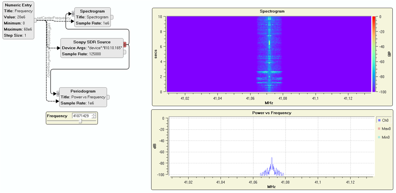
The most basic one is creating a waterfall visualization:
image

One thing that I noted is that PothosSDR keeps sending error messages in its log pane, complaining about SDR Play service being missing. Thing is, I don’t own a SDR Play device, so I don’t need to install any of their support software, but I sill don’t want to see all those error messages. The solution is to rename/remove the sdrPlaySupport.dll file in the Pothos SDR installation folder (C:\Program Files\PothosSDR\lib\SoapySDR\)

To find out which values to use for the device parameters, one has to use the SoapySDRUtil.exe binary from the bin folder like so:

SoapySDRUtil.exe --args="driver=redpitaya,addr=1.2.3.4" --rate=1250000 --direction=RX

If this gives you samples at near the required rate, you are all setup.

But another strange thing is that the Sps field in Pothos could not go above 125000 when the command line clearly allows for more!

The next step was to use rtl_433 which required downloading the specific “Soapy enabled” version from the project releases and placing it inside the PothosSDR bin folder.

You can use the same device string as before with rtl_433 like so:

rtl_433-rtlsdr-soapysdr.exe -d driver=redpitaya,addr=1.2.3.4 -f 40000000 -Y classic -s 125000 -vv

You will notice that one must use the IP address because none of these programs are actually mDNS enabled. The easiest method to get the address from the name, is to simply ping it:

ping -4 rp1234.local

Sadly, initial tests did not work because the RedPitaya Soapy plugin only supports CF32 format where CU8 is the one expected as discussed here: https://github.com/merbanan/rtl_433/discussions/3701

Converters appear not to kick in, so it was suggested to use SoapyRemote with a split approach:

In a first window, start

SoapySDRServer.exe --bind=127.0.0.1

In a second one, start the test command line:

SoapySDRUtil.exe --args=" driver=remote,remote=127.0.0.1, remote:driver=redpitaya, remote:addr=10.10.10.165" --rate=1250000 --direction=RX

If that works, move to rtl_433:

rtl_433-rtlsdr-soapysdr.exe -d driver=remote,remote=127.0.0.1,remote:driver=redpitaya,remote:addr=1.2.3.4

Sadly, this did not help either because it all comes down to the fact that the RedPitaya SDR Soapy module only advertises and supports the CF32 format for the I/Q stream, when rtl_433 did not know what to do with it.

The rtl_433 author was kind enough to create the needed patch and it now accepts the CF32 format just fine. It just needed refinement with the real device at hand, as it seems the Soapy driver immediately returns when the buffers are empty, instead of respecting the configured timeout. That patch has been submitted for review and might land in the future.

However, no signal could be seen which I suppose is due to the 60MHz maximum frequency which is way lower than the default 433.92MHz frequency for rtl_433.

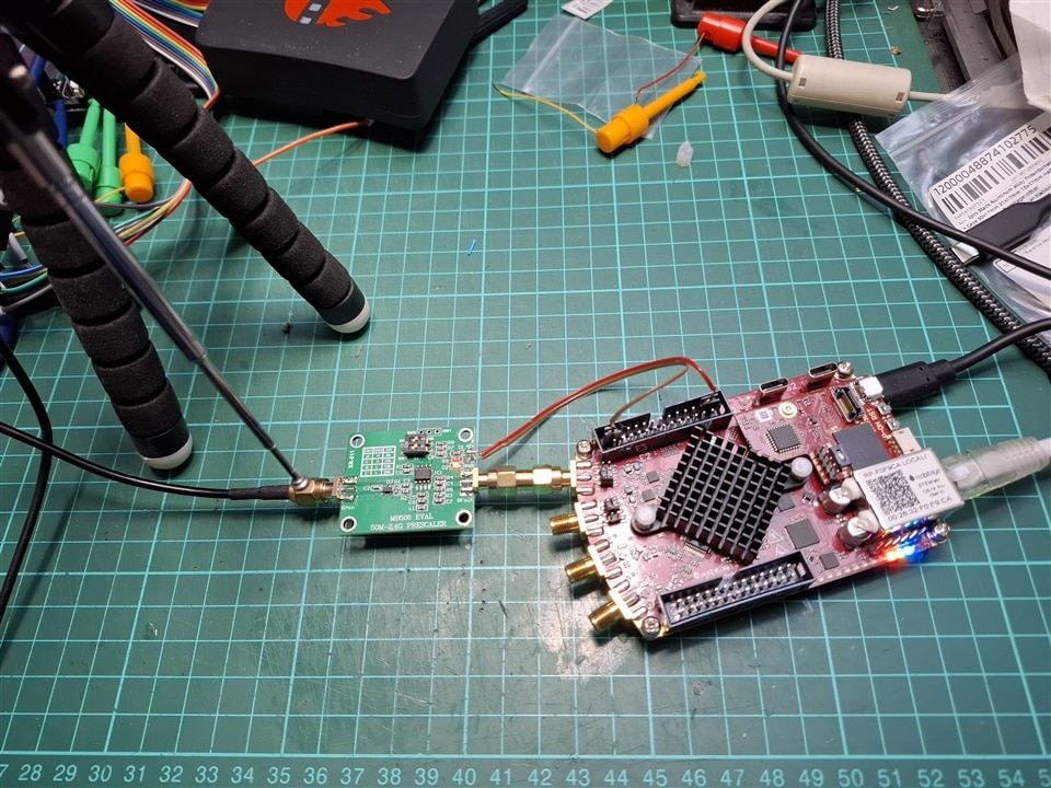
I thus ordered a MB506 frequency divider eval board so that I could “bring” the frequency of interest down into the RP supported range. Note that I would have preferred a “divide by 8” setup but the MB506 was the only one coming up at a reasonable price. 433.92 divided 64 gives 6.78 so this is the frequency to use later on.

As this board needs a +5V supply, I looked at the documentation for the E1 and E2 connectors, and sure enough, there is such a power source here. However, the diagram inside the documentation is of so poor quality that I had to double check the signals position:
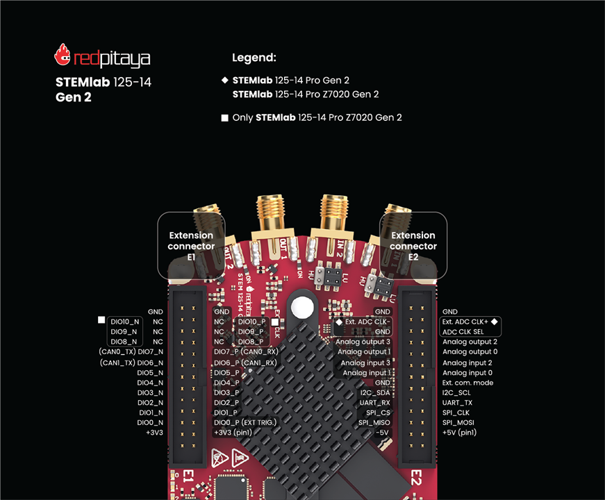
image

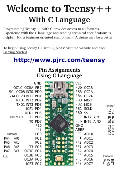
Even a Teensy++ 2.0 documentation that dates from over 10 years ago is better at aligning pin descriptions:
image

 Once hooked up, there is something else that is also missing from the documentation: the recommended LV or HV jumper position. I mean, how do I know what’s needed here?

The MB506 datasheet talks about 1.6V peak to peak so I guess it’s HV but if I was not to use that board, what value could I expect from a regular antenna?

Here is the setup that I ended up with:
image

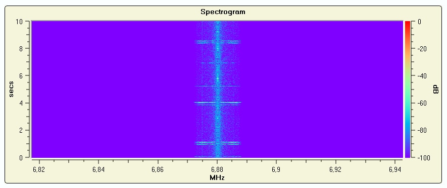
And using PothosFlow, here is what I see every time I press the transmit button on the temperature sensor:
image

So, it seems there is something perceived by the SDR part, but sadly, this is not picked up by rtl_433, which is most likely because its too distorted. Note that I tried with LV and HV, the LV setting gives a stronger “color” on the graph but no change from rtl_433 point of view.
It does not come as a big surprise as it was hinted to me that the MB506 chip acts on the strongest signal it sees in its range, which in my case might well be the zigbee or wifi networks used in the house. I would thus need to add a passband filter in front of it, which, well, is a bit illogical if one is aiming at using an SDR that should do all this in software. At least now, I have RMA connectors!

I will not describe transmit here because colporteur already did it just fine, and also because its max frequency is 60MHz which once again is totally not usable for me. I understand that with a 125MHz core, it can only recreate up to 62.5MHz signals (Nyquist/Shannon laws) but that’s not suitable for my original intent of emitting on 433MHz to see if I could overcome my own legitimate sensors.
One thing that should be doable is to have an external carrier frequency generator, and use the signal from the RedPitaya to modulate that carrier. But what’s the point of a SDR if you have to process the signal with external addons?


This blog is part of 7-part series for my Red Pitaya STEMlab 125-14 PRO Gen 2 Starter Kit roadtest:

Blog 1 – Unboxing the Red Pitaya STEMlab 125-14 PRO Gen 2 Starter Kit
Blog 2 – First contact with the Red Pitaya STEMlab 125-14 PRO Gen 2
Blog 3 – Oscilloscope application in the Red Pitaya STEMlab 125-14 PRO Gen 2
Blog 4 – Logic analyzer application in the Red Pitaya STEMlab 125-14 PRO Gen 2
Blog 5 – Software defined radio with the Red Pitaya STEMlab 125-14 PRO Gen 2
Blog 6 – Developing for the Red Pitaya STEMlab 125-14 PRO Gen 2
Red Pitaya STEMlab 125-14 PRO Gen 2 roadtest report

  • Sign in to reply
  • shabaz
    shabaz 7 hours ago in reply to jc2048

    Nice find.. I forgot about Coilcraft. They also have this one, a bit cheaper (not much):

    PWB-4-BLC COILCRAFT, RF Transformer, 0.14 - 700 MHz, 1:4 | Farnell® UK

    • Cancel
    • Vote Up 0 Vote Down
    • Sign in to reply
    • More
    • Cancel
  • jc2048
    jc2048 8 hours ago in reply to shabaz

    Farnell do a Coilcraft one

    https://uk.farnell.com/coilcraft/wbc4-1tlc/wideband-transformer-1-4-0-25/dp/2458087

    That claims it goes to 750MHz. Farnell prices of course, but you know what you're getting. It's on an SMD carrier, but you could repurpose it 'dead bug' style for a prototype.

    That's what Pitaya used on the frontend of the STEM-122-16SDR board, though they're just using it to up the sensitivity and go from unbalanced to balanced (and to provide some level of isolation for the input, of course).

    image


    I'm not entirely sure what they're doing there. Obviously the shortwave bands can be recovered directly. But I think they may also see it working with the 2m band by undersampling (folding down an aliased image to 20-something MHz), and then quadrature resampling from the 122.88Msps stream at 30Msps for the processing. But as I say, I'm not well enough versed in DSP techniques to be at all sure. If it worked it would be very nice (to a radio amateur), as it would serve up the whole band. [Note: if anyone wants to try it, it would need a good RF bandpass filter to stop anything out of band].


    For the LO, perhaps consider whether something could be done from the FPGA. If it's a SERDES part, then it ought to be possible to contrive something around 400MHz.

    • Cancel
    • Vote Up 0 Vote Down
    • Sign in to reply
    • More
    • Cancel
  • shabaz
    shabaz 9 hours ago in reply to jc2048

    Great find with that Maxim part, it looks perfect for this.. plus it is a double-balanced mixer, and is in an easy-to-solder package (SOT-23-6), and low cost! I'm going to buy a few of those in my next order, they look very useful.

    A dual-gate MOSFET should work well too.

    I looked around to see what I had, and found some NXP PMBD353 dual-diodes, the datasheet mentions UHF mixer suitability so perhaps a passive mixer with two of them could be possible at those frequencies.. something like the setup in the photo below, which used some other diodes which I can't recall, and was only tried at a few tens of MHz.

    Since not everyone likes winding coils! there is TC4-1T (avail from AliExpress etc), since the original Minicircuits ones are usually a lot more expensive and harder to obtain (Farnell doesn't have them). However 400MHz is approaching the limits of those transformers.. but should still operate. One downside is loss, but if the transmitting device isn't far away that would be fine. 

    image

    The ~400 MHz LO is still to be solved, but those RF transceiver chips could be a fairly cheap way to do that (e.g. a ready-made module).

    • Cancel
    • Vote Up 0 Vote Down
    • Sign in to reply
    • More
    • Cancel
  • obones
    obones 10 hours ago in reply to Qbit

    Thanks, that's something that can be a defect at times, but when I get the feeling that things should work as designed, there is that little voice that keeps bugging me at the oddest of times. And it won't get quiet until I find a solution, like that was the case with the MAX32666FTHR board during the Fun & Games contest

    • Cancel
    • Vote Up 0 Vote Down
    • Sign in to reply
    • More
    • Cancel
  • jc2048
    jc2048 16 hours ago in reply to shabaz

    Not my area, but could you get a dual-gate mosfet mixer to work at 400MHz with SMD parts on a board? Back in the day, radio amateurs used them a lot on the 2m band, and that was sometimes with conventional components lashed together above a piece of pcb material.

    Alternatively, there are still small mixer chips available. This Maxim one does 400MHz to 2.5GHz:

    https://uk.farnell.com/analog-devices/max2680eut-t/downconverter-mixer-0-4-2-5ghz/dp/2517314

    Not sure, but the 400MHz lower limit seems to relate to matching with the buffer amplifiers, rather than the mixing cell, so might be usable much lower if you had a preceding preamp that matched nicely to the mixer rather than aiming for a strict 50R all round.

    With the SDR board Pitaya did for radio amateurs, it looks like they undersampled for the 2m band (no mixer or LO), but of course that's not possible with this board because of the hard low-pass filtering ahead of the ADC.

    • Cancel
    • Vote Up 0 Vote Down
    • Sign in to reply
    • More
    • Cancel
>
element14 Community

element14 is the first online community specifically for engineers. Connect with your peers and get expert answers to your questions.

  • Members
  • Learn
  • Technologies
  • Challenges & Projects
  • Products
  • Store
  • About Us
  • Feedback & Support
  • FAQs
  • Terms of Use
  • Privacy Policy
  • Legal and Copyright Notices
  • Sitemap
  • Cookies

An Avnet Company © 2026 Premier Farnell Limited. All Rights Reserved.

Premier Farnell Ltd, registered in England and Wales (no 00876412), registered office: Farnell House, Forge Lane, Leeds LS12 2NE.

Follow element14

  • X
  • Facebook
  • linkedin
  • YouTube