RoadTest: Keithley 2450 SMU with I-V Tracer Software
Author: neuromodulator
Creation date:
Evaluation Type: Test Equipment
Did you receive all parts the manufacturer stated would be included in the package?: True
What other parts do you consider comparable to this product?:
What were the biggest problems encountered?:
Detailed Review:
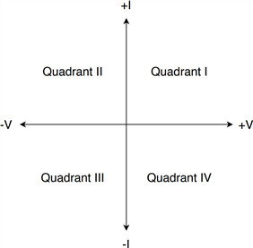
Before presenting the instrument, let's begin with the basics: What is a Source Measure Unit (SMU)? An SMU is an instrument that can perform 4 operations: source voltage, source current, measure voltage and measure current. In contrast to common power supplies (which can also do that), SMUs can operate in all 4 quadrants of the I/V plane, as a power source (quadrant I & III) and as a power sink (quadrant II & IV).
Another important difference between common power supplies (or electronic loads) and SMUs is that the latter can source/sink with less noise and can cover a much wider dynamic range (ie: Keithely’s 2450 SMU sourcing/measuring spans 5 decades of voltage and 9 decades of current range). Even though SMUs could be used as power supplies, electronic loads, voltmeters (by setting them as 0 A sources) or an ammeter (by setting them as 0 V sources), their real strength lies in their ability to move anywhere (within their limits) in the I-V plane to perform tasks such as voltage or current sweeping. The programmability and tight integration of multiple functions into a single instrument, make SMUs extremely versatile DC instruments.
In terms of measurement capabilities, SMUs tend to be capable of measuring much lower currents than DMMs, and have a lower burden voltage (the voltage drop across the terminals when measuring current) compared to DMMs. This occurs because DMMs usually use a shunt ammeter (left circuit), while SMUs usually use feedback ammeters (right circuit). For sake of comparison, The Keithley DMM6500 burden voltage can get > 1 V while for the Keithley 2450 it is guaranteed to be < 100 μV.


Of course, SMUs are not a complete replacement for DMMs, SMUs cannot perform AC voltage or AC current measurements for instance.
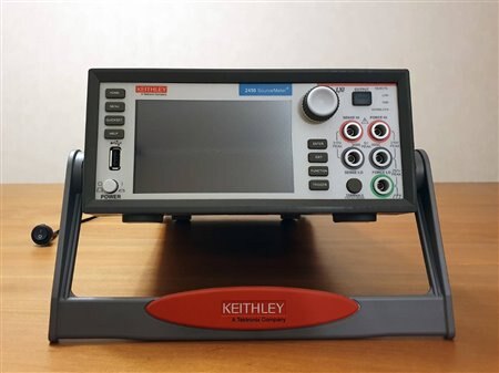
The Keithley 2450 was the first instrument introduced by the company that used their modern touch-screen-based “Touch, test, invent” form-factor. But before diving deeper into more details, it might be interesting to take a quick look into the history of Tektronix/Keithley curve-tracers and SMUs.
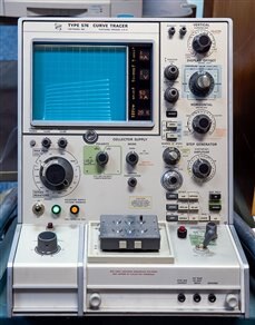
Curve tracers are roughly the integration of a power supply and an oscilloscope in a single package. They were introduced by Tektronix in 1955, and initially designed to trace I-V curves of vacuum tubes. Later they also supported tracing transistors, diodes, and other solid-state devices. Curve tracers work by sweeping a voltage while measuring the amount of current and plotting the I-V trace, traditionally, on a cathode ray tube (CRT). These instruments could deliver voltages up to Kilovolts and currents up to tens of ampere to the device under test (DUT), but what they had in power they lacked in measurement accuracy.

Nowadays there are multiple instruments that can perform I-V curve tracing and their names vary widely depending on their target usage. In contrast to classic curve tracers, SMUs are smaller, have a much wider sourcing/measuring dynamic range, and are much simpler to use.
Keithley began producing their first SMUs (series 23x) in 1989. These full-rack instruments, like other Keithley instruments of that era, were brown and used red LED displays. They used triaxial connectors at the back of the instrument and were programmed through a GPIB (IEEE-488) port.

In 1995 Keithley introduced their half-rack line of SMUs (2400, 2401, 2410, 2420, 2425, 2430 and 2440). The line switched to vacuum fluorescent displays (VFDs) and banana jacks in the front and back of the instrument, and added an RS-232 programming interface.

In 2005 Keithley introduced with the 2601 and 2602, their high-throughput automated production testing oriented line of SMUs (series 26xx). They used a similar form factor than previous VFD half-rack SMUs, except that they removed the front banana jacks and put a navigation wheel instead. Later other form factors were added to this series, such as full-rack VFD ones. One of the most important characteristics of this series is that they introduced a script engine that could run TSP scripts (Lua language scripts).
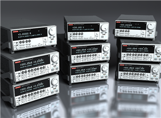
In 2013 Keithley introduced a modern line of instruments that they called “Touch, test, invent”. These instruments (2450, 2460, 2461 and 2470) use a touch screen with a very intuitive graphical interface which responds to a range of gestures (borrowed from smartphone and tablets). Just like the 26xx line of SMUs, this line also supports scripting, but also modern programming interfaces such as USB and Ethernet (which were not implemented in the early 26xx instruments).

The Keithley 2450 comes with:


At first sight instrument looked physically well designed. It comes with front and back bumpers that allow easy "Lego-like" stacking of multiple instruments, but can also be mounted on a rack if needed (the instrument is half-rack 2U high). The display is matte and has a decent viewing angle and brightness.
When the instrument is in output-on state, the switch illuminates very bright, serving in this way as a good warning sign (as the instrument can seriously injure the user if not manipulated with care). Rubber buttons with text on them are back-lit, making them easy to find in low light conditions. The instrument uses status lights to indicate the status of the the front/back connection, remote control, LAN, IEEE 1588 and Interlock (It is worth noting that the 1588 functionality is not supported at the time of writing).

The Keithley 2450 is a 1 channel 20 W SMU that can source from -200 V to 200 V and from -1 A to 1 A. Below 20 V the instrument can source or sink up to 1 A, while over 20 V only 100 mA.

The sourcing/measuring dynamic range of the instrument is impressive. To highlight the dynamic range capabilities of the SMU let’s compare it to a DMM of a similar price tag. The DMM 7510 is a 7½ digit DMM that costs $4,480, while the 2450 is a 6½ digit SMU that costs $5,680. The voltage range of both instruments covers 4 decades, the SMU can go from 20 mV to 200 V, while the DMM from 100 mV to 1 kV. The current range of the SMU covers 8 decades, from 10 nA to 1 A, while the DMM covers only 6 decades, from 10 μA to 10 A.
These are the key specifications of the SMU:

The instrument uses banana jacks at the front and triaxial terminals at the back.
The frontal banana jacks are useful to quickly perform tests that do not require high precision (like measuring/sourcing in 10 or 100 nA ranges). The front panel is easily accessible, and banana cables and connectors are common and inexpensive. There are 5 banana jacks: FORCE HI, FORCE LO, SENSE HI, SENSE LO, and chassis ground. Sourcing/measuring can be done using just the 2 FORCE terminals, but under certain conditions, such as high current or low DUT resistance, the voltage measurement can differ considerably from the voltage that is seen by the DUT. Leads have a low but non-zero resistance, and high currents increase the voltage drop across the leads. The test leads and DUT form a voltage divider, so low DUT resistances reduce the fraction of the sourced voltage seen by the DUT.

A solution to this problem is to use 4 wires (FORCE and SENSE) instead of 2. The FORCE connection operates just like in the 2 wire configuration, but the voltage is measured with 2 extra leads that connect directly to the DUT leads. So even though the SENSE leads still have a low but non-zero resistance, the current that flows through these leads is negligible causing in this way a negligible voltage drop across the SENSE leads. This makes, for almost all practical purposes, the voltage seen by the SMU SENSE terminals almost identical to the one seen by the DUT.

To get accurate readings in noisy environments or when operating at low currents (<1 uA), extra precautions must be taken. There are 2 useful approaches for these situations: shielding and guarding. Shielding requires using shielded cables and an enclosure around the DUT that are electrically connected to the FORCE LO. This reduces the introduction of external noise into the test circuit, but does not solve the current leakage between the FORCE HI, and FORCE LO, which at low currents could add a significant error. To reduce the leakage, a guard must be used. A guard is a buffered output that is nearly at the same potential than the lead that it guards (FORCE HI and SENSE HI). By keeping the voltage difference between the guard and the guarded lead close to 0, the current leakage is reduced proportionally to the voltage difference (Ohms law).
The following image shows how guarding reduces cable leakage:

The triaxial connectors look similar to BNC connectors, but they possess 3 conductors instead of 2. The instrument uses 3 lug triaxial connectors, so it is not possible to damage the terminals by mistakenly plugging a BNC connector (as it often occurs with 2 lug triaxial connectors). The inner conductors are not different to the front panel connectors (FORCE LO, FORCE HI, SENSE LO and SENSE HI). The middle conductors are FORCE LO for the FORCE LO and SENSE LO terminals and GUARD for the FORCE HI and SENSE HI terminals. The outer conductors are connected to the chassis ground.

It may appear as there is no advantage in making unshielded, unguarded measurements as they are inferior, but triaxial connectors, cables and test fixtures are very expensive (in the order of several hundreds of USD) and it may take more time to setup the DUT in a fixture than to just grab the leads of the DUT with the probe hooks. Moreover, in many cases it will not make much difference to perform shielded and guarded measurements.
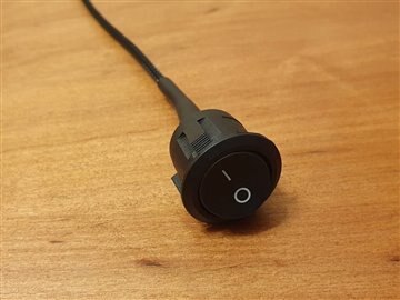
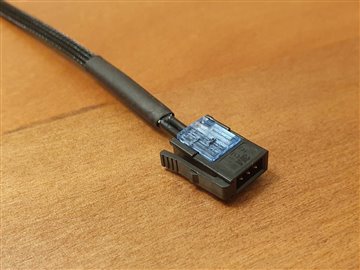
The interlock is a protection switch that is used as a safety mechanism to protect the user from getting shocked with voltages greater than ±42 V. The connector (3M™ Mini-Clamp Plug) contains 3 pins: ground, interlock and 6 V DC. When the 6 V and interlock pins get shorted, the SMU can source voltages up to ±200 V. The interlock switch may be installed on the lid of a test fixture, so that opening the fixture opens the switch while closing it closes it. I installed just a common switch to manually control its state.

The instrument can be controlled remotely through multiple ports: GPIB, USB, and Ethernet. They are more or less equivalent, but the USB is the fastest, followed by the Ethernet and GPIB. Triggering, required for synchronization, has the highest consistency and lowest latency through the GPIB port, followed by a less consistent and higher latency USB port and the Ethernet port at last. Ethernet is the most flexible one, it supports controlling the instrument through VXI-11, raw sockets, telnet, or even a web server that runs in the instrument.
When the instrument is being controlled remotely a front panel LED lights up. The remote control of the instrument does not disable the front panel display or the instrument menus, but if one tries to change a parameter, the instrument prompts to switch to local control.
The digital I/O port uses a DB-9 connector to provide 6 configurable input/output lines, a 5 V (500 mA max) line, a ground line and a flyback diode clamped line. These lines can be used to read or write data, as trigger input or output to synchronize multiple instruments and even to drive and control relays.

The TSP-Link is a proprietary high-speed trigger synchronization and communication bus implemented recently in the newest Keithley instruments. It allows to daisy-chain connect multiple TSP-Link instruments in a master/slave configuration with inexpensive LAN Cat 5e (or higher) crossover cables. TSP-Link allows the master to control multiple instruments as if they were one single physical instrument.
The instrument can be controlled through multiple interfaces, let's take a look at some of them.
The front panel interface is intuitive and simple to navigate and use. The menu hierarchy is very shallow, making the access to every options very quick. Most options are available immediately after a single click on a menu icon (in contrast to the tedious navigation of deep menu hierarchies seen on many instruments). The fonts and number are big and easy to read and the color palette is pleasant. The GUI supports different gestures such as dragging and pinch-to-zoom, and it feels almost as intuitive as using a smartphone.

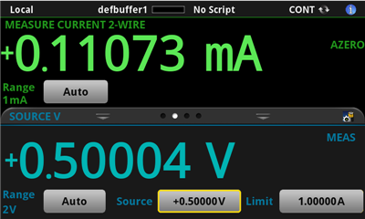
The home screen shows at the top what is being measured and at the bottom what is being sourced. What is being sourced and measured can be changed by pressing the FUNCTION physical button.

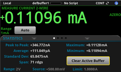
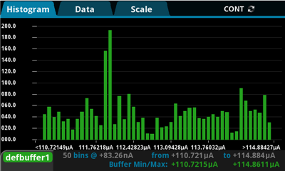
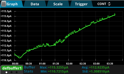
The instrument can display the statistics, the table, the histogram and the graph of the data to quickly explore it.

Performing a current or voltage sweep is very simple:


Setting the instrument as a voltmeter, ammeter, ohmmeter or power supply is also very simple as well, it requires pressing the QUICKSET physical button followed by pressing the desired operating mode.

All in all the front panel user interface looks very polished and functional, its quite visible that Keithley put a lot of effort in making it good.
The SMU hosts a web page that can be used to set some configuration settings (network configuration, time and date), check the instrument status (configuration, system information, event log), remote control the instrument through a virtual panel, download the data buffers (as CSV files) and send SCPI/TSP commands. Probably the most useful feature of the web interface is the virtual front panel, which can be used to control the instrument almost in the same way as from the physical front panel. Some relevant differences between the virtual and physical front panel are that the virtual panel is less responsive (it refreshes at ~3 refreshes/s) and it does not support the pinch-to-zoom gesture. More than trying to replace the physical front-panel interaction I found that the virtual front panel particularly useful when debugging TSP scripts to easily check the status of the instrument when sitting in front of the computer.


KickStart is an application to control to multiple instruments from Tektronix and Keithley such as DMMs, SMUs, power supplies, and oscilloscopes. The application is very simple and intuitive, you select the instrument you want to control from the left side of the screen, set the instrument settings, press the "play" button, and then check the captured data either from the table or the graph view. The application can set the SMU to operate as a voltage or current source, and perform either voltage or current sweeps. Sweeps can be linear, logarithmic, or of arbitrary values of voltages or currents. Most of the settings available from the front panel are available in KickStart making it a good replacement for the front panel usage. Advantages of KickStart over using the instrument from the front panel are that the data can be more easily explored through either the graphing capability or the data table, and that it can save the data (as CSV files) directly to the computer. One of the features that I liked the most about KickStart is that I can see the data as it gets measured from the instrument, in this way I can interrupt the measurement if I don't like the data that I'm capturing (ie: if parameters were set wrong).


When more complex operations need to be performed, programming the SMU is the only alternative. The instrument can be programmed with either SCPI commands or TSP scripts, but latter is far more powerful. TSP is the name for Keithley's adaptation of Lua to control their newest instruments. In contrast to SCPI, TSP scripts can run in the SMU itself without a controlling computer. The scripts can be stored in the instrument's non-volatile memory and executed in a stand-alone way, or sent from a computer and then executed in the instrument. Scripts can be saved to the instrument's non-volatile memory either remotely from a computer or with a USB drive.
Here is an example of a script that could be used to measure the resistance and the power delivered to a resistor when sourcing 10 V.
-- Reset environment variables to the default reset() -- Set instrument as a voltage source (can be omitted as this is the default value) smu.source.func = smu.FUNC_DC_VOLTAGE -- Set the current limit to 1 A smu.source.ilimit.level = 1 -- Set the source voltage to 10 V smu.source.level = 10 -- Set measurement to current (can be omitted as this is the default value) smu.measure.func = smu.FUNC_DC_CURRENT -- Turn the output on smu.source.output = smu.ON -- Perform a single measurement smu.measure.read() -- Turn the output off smu.source.output = smu.OFF -- Read the measured voltage value v = defbuffer1.sourcevalues[1] -- Read the measured current value i = defbuffer1.readings[1] -- Print voltage print(v) -- Print current print(i) -- Print resistance print(v / i) -- Print power print(v * i) |
The script generated the following output on my computer when tested with a 270 Ω resistor:
10.000008583 0.037293303758 268.14488327 0.37293335767 |
The previous script requires a computer as print() outputs to the controlling computer only. It is also worth noting that the voltage was also measured because it may not completely match the voltage that the SMU tried to source, for instance when the SMU hits the current limit (which here was set to the maximum value of 1 A).
To use the code in a stand-alone way, some minor modifications need to be made in order to output the values to the instrument screen.
-- Reset environment variables to the default reset() -- Set instrument as a voltage source (can be omitted as this is the default value) smu.source.func = smu.FUNC_DC_VOLTAGE -- Set the current limit to 1 A smu.source.ilimit.level = 1 -- Set the source voltage to 10 V smu.source.level = 10 -- Set measurement to current (can be omitted as this is the default value) smu.measure.func = smu.FUNC_DC_CURRENT -- Turn the output on smu.source.output = smu.ON -- Perform a single measurement smu.measure.read() -- Turn the output off smu.source.output = smu.OFF -- Read the measured voltage value v = defbuffer1.sourcevalues[1] -- Read the measured current value i = defbuffer1.readings[1] -- Print voltage to the first line of the user tab display.settext(display.TEXT1, string.format("Voltage: %.4f V", v)) -- Print resistance and power to the second line of the user tab display.settext(display.TEXT2, string.format("R: %.3f \018, P: %.3f W", v / i, v * i)) |
And this, produced the following output:

As it can be seen, the basic functionality is straightforward. To perform more complex operations more advanced concepts need to be learned, such as trigger models, configuration lists and timers.
To show the capabilities of the instruments I performed a few experiments. All the code and data used can be found in my GitHub repository.
I connected a small solar panel to the instrument to show how the different user interfaces (front panel, Web, KickStart, Keithley’s I-V tracer APP and the TSP scripting engine) are used to perform the same task of measuring the Pmax, Vmax, Imax, Voc and Isc values.
Keithley 2450: Solar cell characterization
I used a TSP script made by Keithley to characterize the Voc and ESR curves of a 18650 lithium battery. The script outputs 2 files, where one of them can be used with the Keithley 2281S Battery simulator. I used Python to parse one of the output files and plot the battery discharge curves.
Keithley 2450: Battery characterization
I used the SMU and the Keithley DMM6500 to measure the efficiency of a DC-DC converter at varying input voltages. I used KickStart to synchronize the instruments and then Python to integrate the measurements and generate an efficiency plot.
Keithley 2450: DC-DC converter efficiency measurement
I generated I-V curves of LEDs of 6 different types to see how much their curves spread for each type. I also performed a simple overcurrent stress test to measure how it affects the I-V curve of the LED.
Keithley 2450: LED characterization
I programmed the SMU using configuration lists, a timer and a trigger model to measure the dielectric absorption of different type of capacitors.
Keithley 2450: Capacitor characterization
I programmed the SMU to connect to a server and continuously stream the measured data to a database to finally make it available to a web-based dashboard.
Keithley 2450: Remote Monitoring
The 2450 is an impressive instrument. Its electrical specifications are excellent, which is not unexpected as the company has more than 30 years of experience making SMUs, and currently offers a wide variety of SMUs for almost any need. The support of all kind of interfaces such as GPIB, Ethernet, USB, TSP-Link and digital I/O make the instrument interfacing extremely flexible. The variety of workflows that the instrument supports gives the user freedom to chose whatever suits him/her better for the application. One of the greatest features of the instrument is the support of the TSP scripting language which makes the instrument extremely flexible and not dependent of a computer. The ability to run scripts in standalone also increases the speed at which the instrument can react and perform tasks, as there is no latency caused by sending data back and forth to a computer. This may not be important in a laboratory environment, but could have a major impact in production testing.
All in all my experience with the instrument was great, except for one issue.
I received a defective unit that overheats and shuts down the output when sourcing at "high" power. I contacted Keithley and they will replace my unit.


Top Comments
Well done and interesting review. I like how you broke the experiments off into separate blogs.
Thanks brycewilkins, yes you can buy the connectors, the cables and a metal box to build a test fixture, but connectors and cables would still cost you quite a bit, and it may still take quite a bit of…
You can build your own but the connectors are quite pricey and the selection of cable is quite critical. Triaxial cable is not particularly easy to find or easy to terminate, but another consideration…