


TI's SDK for the MSPM0 family has a set of examples. They are all targeting one of their LaunchPad dev kits. In this post, I'm porting another one to the EasyL1105.
The example, adc12_triggered_by_timer_event_stop, combines an ADC design with low power. It's originally written for the LP-MSPM0C1106 LaunchPad. I'm porting it (just like I did in Port an SDK example to the EasyL1105 MSPM0 board ).
What does this project do?
It lingers in lowest power mode. Then gets woken up by a timer, to retrieve ADC samples and drive a GPIO based on the measurement.
- It goes to lowest power mode for a second
- a timer expires, and wakes the controller up
- then a loop of
- taking an ADC sample while in sleep mode
- make decisions based on outcome and drive a GPIO, in active mode
- if ADC input is below VREF (1.5V) , switch on LED
- if above VREF, switch off LED
- back to 4
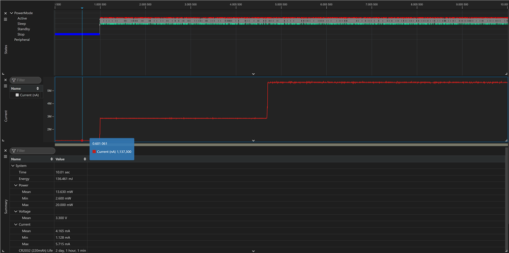
In the EnergyTrace capture below, you see 3 clear steps, showing 3 phases in the execution:
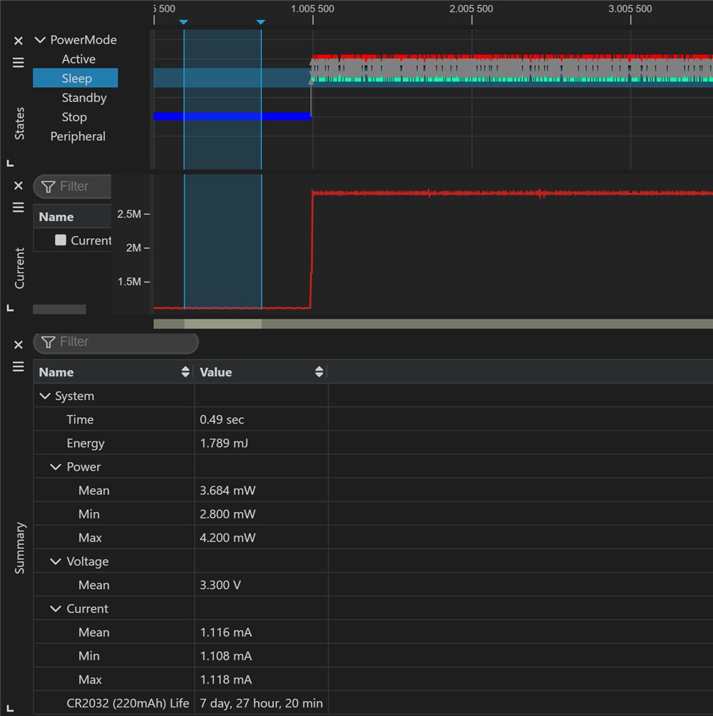
- stop mode, waiting for wake-up by the timer
- toggling between Sleep and Active, but comparator decides that LED has to be OFF
- same, but our ADC input dropped below VREF. The LED switches on and consumes significant current.
Port from TI's SDK example
There's one change we have to do. Our LED is on P27. And it's a standard output (not open drain).
I've done a few other changes, to take care that the I2C (not used) pull-ups don't draw current.
| Peripheral | Function | MCU Pin | Board Pin | Comment |
|---|---|---|---|---|
| GPIOA | Output | PA27/2 | Green LED | |
| I2C | Open-Drain Output | PA0/4 SDA | not used | open drain driven low for power saving (no current through pull-up) |
| I2C | Open-Drain Output | PA1/5 SCL | not used | open drain driven low for power saving (no current through pull-up) |
| TIMG1 | ||||
| ADC0 | ADC12 Channel 2 Pin | PA25/28 | J2/9 | signals below VREF will switch on green LED |
| EVENT | ||||
| BOARD | Debug Clock | PA20 | J14_4 | |
| BOARD | Debug Data In Out | PA19 | J14_2 |
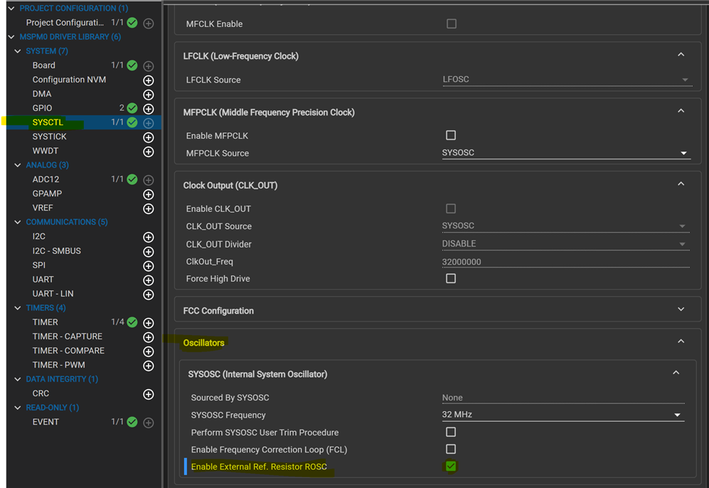
Last change I did, is flag that we have a resistor on board that stabilises the low frequency oscillator. This doesn't result in a measurable power save or loss. But we have it, so let's flag that:
Test
After flashing the board (with bootloader or debugger), you can test the firmware.
ADC input is ADC12 Channel 2 on PA25. On the EasyL1105, this is J2.9. It 'll check for voltages between 0 and 1.5V, and voltages between 1.5 and 3.3V.
After a second of being in the lowest power mode (STOP), the controller wakes up, and starts sampling.
While sampling, it tries to stay in a lower power mode (SLEEP)
Then the controller goes to ACTIVE mode to make decisions and drive the LED. Then drop back to SLEEP.
It does that continuously.
You can see the behaviour by switching the ADC input between 0V and 3.3V (or if you want, use a potentiometer).
While sleeping and when voltage is high, the green LED is off. When above 1.5V the LED is on.
Use a low burden voltage current meter (or better tools*1) to assess power usage.
EnergyTrace++
If you have an EnergyTrace compatible debugger, you can use it to analyse the power consumption in css:
1 an EEVBlog µCurrent with a multimeter or an oscilloscope, or a bench meter (E.g.: Keythley DMM6500) will do the job.
When you're finished
Low power designs can put your controller in a state, that makes it hard to reprogram it later.
After I'm done testing a low power design, I prefer to re-program it with non-low-power firmware (E.g.: a blinky).
For this design, after you are done,
- Open a non-low power design in CCS
- connect it to a debugger
- keep BOOT button pressed.
- Start a debug session. Only release BOOT when your debugger is at main()
This will save you headaches later.
Have fun!
ccs project adapted to EasyL1105: adc12_triggered_by_timer_event_stop_20250918.zip


