


In an earlier post, I tested the EasyL1105 MSPM0 kit with Code Composer Studio and an XDS110 debug probe. That blog covered the standard functionality: program the device, step through the code. This time, I try the EnergyTrace++ option.
EnergyTrace++ analyses the power consumption of your design. While doing that, it collects info from controller and debugger. It the displays the results. Amongst the data collected: timestamp, power mode, peripheral status.
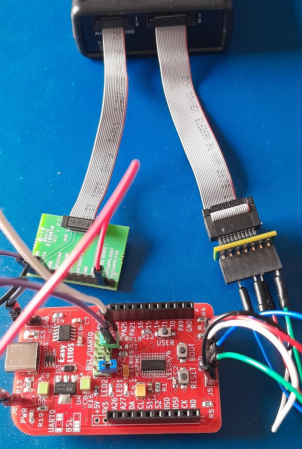
The tracer requires that the debugger provides power to the kit. The XDS110 can do that. Also the on-board debuggers on the MSPM0 LaunchPads. I have not seen other LaunchPads that have the necessary EnergyTrace circuitry.
|
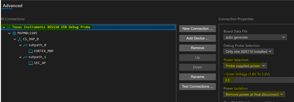
XDS110 option Probe supplied power: when debugging, you can provide external power to your board (e.g.: via the USB). You can also have it powered by the XDS110. On its extension connector, it has a power supply that can deliver between 1.8 and 3.6V. The power will be supplied when you start the debug session. It 'll (optionally) switch off when you stop debugging. You configure that in the targetConfigs advanced settings:
|
First trace
You can make a trace right away. Use one of your own projects. Start a debug session, then Run -> Trace -> Start EnergyTrace++. There are several other ways to do this, but this one is the easiest to document.
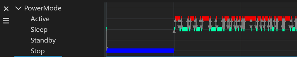
Run the design by selecting Run -> Free Run. After 20 seconds, you get results. Wen you run design that doesn't use low power modes, you 'll typically see something like this:-, where all activity happens in Active (high power) mode.
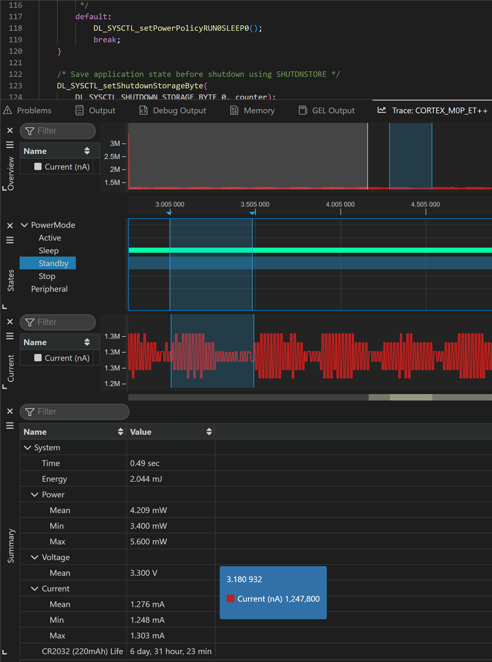
Low Power Mode tracing
It gets more interesting when you try to make a low power design. The trace will help you to see how long the design spends in high vs low power modes. You can also let it calculate the amount of energy burned. In total, or for a particular time range. A good project to start from, is sysctl_shutdown. Available from Resource Explorer, or when you create a new project.
|
warning: when you build low-power designs, always include a mechanism to boot your design in a mode where you can debug or reprogram it. Failing to do this can result in a bricked IC. TI does that in their examples, by checking the logic level of configuration pins at startup. If those pins have a certain value, the device will go into a mode where a debugger or bootloader can take over. You can use patch cables to set those pins in a safe combination. Like jumpstarting a car. When I'm done testing a low power design, I always flash a "normal" power design before the board is put aside. A blinky, or anything that isn't low power. So that I don't have to figure out the next time how to resurrect the device out of its low power state. |
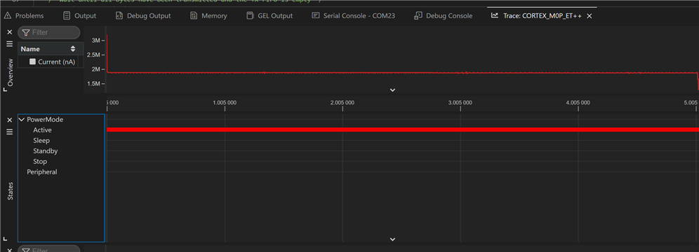
I've ran that one, configured for Sleep power mode. Here is a trace, with collateral. A particular interesting data point: how long will your design survive on one coin cell.
|
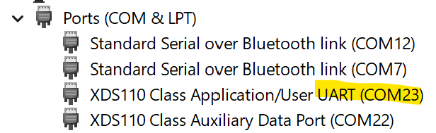
XDS110 option UART-to-USB bridge: The XDS110 has a built-in UART to USB bridge. If you connect the MSPM0 UART Tx and Rx signals with the Rx and Tx pins of the debug probe extension connector, the data is available on your PC trough a COM port.
|
Thank you for reading.

